Publisher’s version / Version de l'éditeur:
Vous avez des questions? Nous pouvons vous aider. Pour communiquer directement avec un auteur, consultez la première page de la revue dans laquelle son article a été publié afin de trouver ses coordonnées. Si vous n’arrivez pas à les repérer, communiquez avec nous à [email protected].
Questions? Contact the NRC Publications Archive team at
[email protected]. If you wish to email the authors directly, please see the first page of the publication for their contact information.
https://publications-cnrc.canada.ca/fra/droits
L’accès à ce site Web et l’utilisation de son contenu sont assujettis aux conditions présentées dans le site
LISEZ CES CONDITIONS ATTENTIVEMENT AVANT D’UTILISER CE SITE WEB.
Paper (National Research Council of Canada. Institute for Research in
Construction), 1987
READ THESE TERMS AND CONDITIONS CAREFULLY BEFORE USING THIS WEBSITE. https://nrc-publications.canada.ca/eng/copyright
NRC Publications Archive Record / Notice des Archives des publications du CNRC : https://nrc-publications.canada.ca/eng/view/object/?id=e286334f-57d3-4d8f-9ece-e8c6caeef447 https://publications-cnrc.canada.ca/fra/voir/objet/?id=e286334f-57d3-4d8f-9ece-e8c6caeef447
NRC Publications Archive
Archives des publications du CNRC
This publication could be one of several versions: author’s original, accepted manuscript or the publisher’s version. / La version de cette publication peut être l’une des suivantes : la version prépublication de l’auteur, la version acceptée du manuscrit ou la version de l’éditeur.
For the publisher’s version, please access the DOI link below./ Pour consulter la version de l’éditeur, utilisez le lien DOI ci-dessous.
https://doi.org/10.4224/40001377
Access and use of this website and the material on it are subject to the Terms and Conditions set forth at
Fire tests on window assemblies protected by automatic sprinklers
Richardson, J. K.; Oleszkiewicz, I.
TH1
INational Research Conseil national Council Canada de recherches Canada
no.
1467
1c . 2 I Institute for lnstitut de
BLDG Research in recherche en
- - Construction construction
I
Fire Tests on Window
Assemblies Protected by
Automatic Sprinklers
by J.K. Richardson and I. Oleszkiewicz
Reprinted from Fire Technology Vol. 23, No. 2, May 1987 - -
p. 115-132
(IRC Paper No. 1467)
Price $3.00 NRCC 27899 N R C
-
CISTj I R CLIDWARY
JAN
?lPYll
B I B L I O T H E Q U E
f R C
CNTC-
lClSTRESUME C On d 6 c r i t d e s e s s a i s a u f e u e n v r a i e g r a n d e u r e f f e c t u s s s u r d e s v i t r a g e s arm& e t t r e m p s s , montes s u r d e s c h b s i s d ' a c i e r e t d ' a l u m i n i u m . Soumis 3 u n f e u n o r m a l i s 6 , c e s v i t r a g e s o n t h p r g s e n t s u n e d u r 6 e d e r s s i s t a n c e a11 f e u d e 4 5 m i n u t e s 3 2 h e u r e s . La d e n s i t 6 d e f l u x d e c h a l e u r r a d i a n t e maximum t r a n s m i s e p a r l e v e r r e a 6t6 r e d u i t e d e p l u s d e 90%. -.
Fire Tests on Window Assemblies
Protected by Automatic Sprinklers
By J. K. Richardson and I. Oleszkiewicz
National Research Council
Ottawa, Canada
Reprinted from FIRE TECHNOLOGY Volume 23, Number 2
May, 1987
Copyright O National Fire Protection Association. All Rights Reserved.
Fire Tests on Window Assemblies
Protected
by
Automatic Sprinklers
J . K . RICHARDSON I. OLESZKIEWICZ
National Research Council, Canada
(Manuscript received July 1986, accepted September 1986)
'I
ABSTRACT
Full-scale fire tests on wired and tempered glazing in steel and aluminum frames are described. These assemblies achieved fire resistance ratings when exposed to a standard fire of 45 min to 2 h.
The maximum radiant heat flux transmitted through the glass was reduced by more than 90%.
INTRODUCTION
I
T
HE USE OF GLAZING in fire separations has been strictly reg- ulated by building codes, including the National Building Code of Can- ada (NBCC).' The NBCC 1985 edition, as with most North American model building codes, limits vertical glazing to wired glass in steel frames; in- dividual panes must not exceed 0.84 m2 in area and must have a maximum dimension of 1.4 m. To the practicing design professional, these limits im- pose a severe restriction on the design of fire-rated assemblies where glazing is desirable or necessary. In particular, the emergence of the atrium building and the need for increased visual contact with building areas for security reasons has created a considerable demand for glazing in fire separations.To determine whether different types of glass, larger areas and dimen- sions, and different framing materials could be used, a series of fire tests was performed a t the National Fire Laboratory of the National Research *. CoQncil of Canada. These experiments examined tempered and wired glass, single and double glazing, significantly larger areas and dimensions, and
steel and aluminum frame materials, all in conjunction with automatic
.
-
sprinkler protection.Reference: J . K. Richardson and I. Oleskiewicz, "Fire Tests on Window Assemblies Protected
1
by Automatic Sprinklers," Fire Technology, Vol. 23, No. 2, M a y 1987, pp. 115-132. I Key Words: Sprinkler systems, wired glass, tempered glass.This pa er is a contribution from the Institute for Research in Construction, National ~ e s e a r c f Council of Canada.
BACKGROUND INFORMATION
Background information for glazing materials exposed to fire is scarce, especially with respect to extended fire resistance ratings. In recent years, borosilicate glazing has been developed to resist the effects of fire.' Because of its high cost, this glazing is not frequently used in North America. There is also a demand for glass pane sizes larger than those available for this ! product.
A tempered glazing system protected by a deluge sprinkler arrangement was examined by Underwriters Laboratories in 1969.3 The system used large quantities of water and required a wetting agent. This glazing system was developed for a 45-minute standard exposure from outside the building as opposed to the NBCC criteria for fire exposure inside the building and for greater exposure times.
Tests were also carried out by Moulen and Grubits in Australia on various glazing materials that were protected by drenchers when exposed to radiant heat.",' These tests demonstrated that such a system would reduce by 90% the radiant heat transmission through glazing materials exposed to a radiant heat flux of 40 kWlm2 (4 Wlcmz). The tests4 also showed that only wired and tempered glass withstood the radiant fire exposure long enough for glass bulb sprinklers with temperature ratings of 68°C and 93°C to ac- tivate.
In the United Kingdom, a similar system using drenchers on glass 6 mm and 10 mm thick has been tested by the Greater London Council Scientific Services B r a n ~ h . ~ In these experiments, float and toughened glass stayed in place up to 70 min when exposed to the "slow heating curve" defined in DIN Standard 4102, Part 3.' Based on this curve, a maximum of 650°C is reached a t 10 min and maintained until the end of the test.
TEST CRITERIA
After evaluating the published information and the needs of North American users, the following criteria were established for the test pro- gram.
1. The glazed assembly should use commonly available equipment and materials, and should not be sophisticated.
I 2. The assembly should be able to withstand a fire exposure as typified
by the standard timetemperature curves for a t least 2 h (at which time in the standard test the radiant fire exposure exceeds 10 Wlcm2).
-.
3. The panes should be as large as possible in both area and dimensions. 4. The sprinkler installation should have closed heads and use onlywater as a cooling agent (i.e., no wetting agent). DESCRIPTION OF THE BURN FACILITY
The tests were conducted in a 1.83 X 2.44 m burn room with a ceiling height of 3.05 m. Three of the walls of the facility, constructed of concrete
Fire Tests on Window Assemblies 117
block 152 mm thick, were protected on the inside with 25-mm refractory -
thermal insulation (Fiberfrax blanket).* The fourth (east) wall was formed by the test window assembly erected on a foundation 0.2 m high. The ceiling assembly was constructed of 19-mm plywood supported on a wood frame
with 38 X 89 mm members. The plywood was protected by 13-mm gypsum
board, 13-mm marinite board, and two layers of 25-mm Fiberfrax blanket.
The room was constructed on a sloping concrete floor (see Figure 1). To
protect the floor and facilitate water drainage from the enclosure, the floor !
was covered with crushed stone, and openings were made in the base of the test wall.
4
Gas
Air
e Control thermocouple Dimensions in m m
Figure 1 Section of b u m room.
DESCRIPTION OF THE GAS AND AIR SYSTEMS
!
Fire exposure was provided by a linear propane burner installed on the
,
.
floor adjacent to the west wall (opposite the test assembly) as shown in
Figure 1. The burner was protected from water spray and steam by a
firebrick wall extending 0.2 m above the burner (0.65 m above the floor).
- - ,
Combustion products and steam were withdrawn through two stacks
with a 0.6 X 0.45 m cross section, located in the north and south walls. To
retain the hot gases in the room but remove the cooler steam, the exhaust *Trade names have been given for cetain products used in these experiments as a means of clarifying specific details. They are not intended as an endorsement of those particular prod-
ucts by the National Research Council of Canada, Fire Technology, or the National Fire Pro-
stack inlets were located near floor level. A sheet steel baffle was installed across the room on the burner side of the exhaust stack to prevent the steam from recirculating.
Air to the burner was supplied a t rates up to 0.9 m31s by a centrifugal forced-air fan with an adjustable damper.
DESCRIPTION OF THE TEST ASSEMBLIES
I
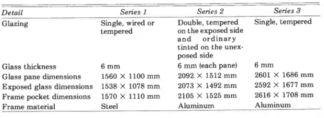
Three types of window assemblies were used, one for each test series. Specific details of dimensions and materials are included in Table 1.
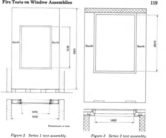
The window frame was installed in an assembly consisting of two layers of 12.7-mm Type X gypsum board on steel studs (see Figure 2). This wall assembly is listed as having a 2-h fire resistance rating.
The hollow frame was made from 16-gauge, fully welded, galvanized steel with a 51-mm face, 171-mm jamb depth and 16-mm high integral glass stop. A standard 20-gauge removable glass stop, 16 mm high and 19 mm wide was fixed to the frame with self-tapping screws.
Tempered or wired glass was installed in the frame using a sealant, shims, and rubber setting blocks, in addition to the glass stop. The glass was not cleaned except for small spots where thermocouples were bonded to the glass.
Aluminum frames were installed in a gypsum board on steel stud assembly as shown in Figure 3. The side of the frame facing the burner was covered with 12.7-mm Type X gypsum board on a 38-mm steel stud. The side of the frame adjacent to the glass was left exposed. The hollow aluminum frame, Kawneer Model 1600, was approximately 3 mm thick, 64 mm wide, and 102 mm deep.
The glass assembly consisted of a sealed double-glazed unit with clear, tempered glass on the fire-exposed side, and solar blue-tinted, ordinary
Table 1 Details of window assemblies.
I -
-Detail Series 1 Series 2 Series 3
Glazing Single, wired or Double, tempered Single, tempered
tempered on the exposed side
-.
a n d o r d i n a r ytinted on the unex- posed side
Glass thickness 6 rnm 6 mm (each pane) 6 mm
Glass pane dimensions 1560 X 1100 mm 2092 X 1512 mm 2601 X 1686 mm
Exposed glass dimensions 1538 X 1078 mm 2073 X 1492 rnm 2592 X 1677 mm
Frame pocket dimensions 1570 X 1110 mm 2105 X 1525 mm 2616 X 1708 mm
Fire Tests on Window Assemblies
D~rnenr~onr ~n rnm
Figure 2 Series 1 test assembly. Figure 3 Series 2 test assembly.
glass on the unexposed side. A sealant, shims, and 6-mm rubber setting blocks a t the bottom edge were used. The glass was not cleaned except where thermocouples were attached.
For the Series 3 test, the aluminum window frame was installed in gyp- sum board on a steel stud assembly as shown in Figure 4. The aluminum frame was exposed to the burn room. The hollow aluminum frame, Kawneer
Model 450, was approximately 3 mm thick, 45 mm wide, and 114 mm deep.
The tempered glass was installed in the frame; a sealant and shims were
used, as well as 6-mm rubber setting blocks placed a t the bottom edge. The * .
glass was not cleaned except for small areas where thermocouples were at- I
tached. 1
.
-
SPRINKLER INSTALLATION
For the tests using sprinklers in Series 1 and for all tests in Series 2 and
3, prototype Grinnell sprinklers were located on the centerline of the glass. They were essentially Duraspeed standard and quick-response types with a deflector design to ensure that water would wet the entire glass surface, especially the upper corners.
F;
Figure 5 Quick-response window sprinkler (series 2 and 3 tests).
Figure 4 Series 3 test assembly.
Figure 6 Thermocouple locations on the glass.
The center of the sprinkler deflector was 32 mm below the lower surface of the top window frame member. The deflector face was 16 mm from the glass. Table 2 lists the sprinklers used in each test.
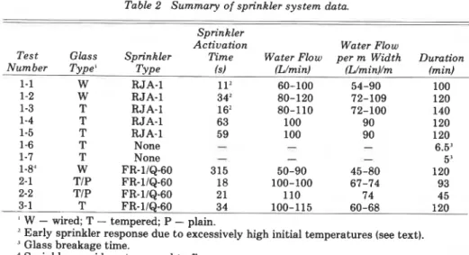
With one exception, in Series 1, the prototype was a 12.7-mm orifice (K factor = 78). Grinnell Duraspeed sidewall sprinkler with a 74°C standard link (Designation RJA-1). In Test 1-8 and in Series 2 and 3, the prototype was a 12.7-mm orifice (K factor = 78), horizontal sidewall sprinkler with a 74°C quick-response link [Designation FR-1IQ-60 (see Figure 5 ) ] . Except for the link mechanism, the standard sprinkler was essentially the same as that shown in Figure 5.
The water flow to the sprinkler, including any variations in flow, is noted
.
.
in Table 2.INSTRUMENTATION
The air temperature of the burn room was monitored by six Type K ther- mocouples (see Figure 1 for locations) enclosed in 6-mm outside diameter in- cone1 sheaths. The thermocouple beads were positioned 610 mm from the sidewalls. The distances between the glass and the thermocouples, and the vertical distribution of the thermocouples differed from the specifications of
Fire Tests on Window Assemblies
Table 2 Summary of sprinkler system data.
Sprin kler
Activation Water Flow
Test Glass Sprinkler Time Water Flow per m Width Duration
Number Type' Type Is) (L/min) (Wminl/m (min)
1-1 W RJA-1 112 60-100 54-90 100 1-2 W RJA-1 34' 80-120 72-109 120 1-3 T RJA-1 16' 80-110 72-100 140
*
1-4 T RJA-1 63 100 90 120 1-5 T RJA-1 59 100 90 120 1-6 T None - - - 6.5' 1-7 T None - - - 5' 1-8" W FR-1IQ-60 315 50-90 45-80 120 d 2-1 TIP FR-1IQ-60 18 100-100 67-74 93 2-2 TIP FR-lIQ-60 2 1 110 74 45 3-1 T FR-11QL60 34 100-115 60-68 120' W - wired; T - tempered; P - plain.
Early sprinkler response due to excessively high initial temperatures (see text). "lass breakage time.
Sprinkler on side not exposed to fire.
CANkS101, "Standard Methods of Fire Endurance Tests of Building Con-
struction and material^,"^ to minimize the influence of water spray on ther-
mocouple readings. The standard test requires that the thermocouples be located 150 mm from the glass whereas in the tests these were located 1420 mm from the glass (beyond the water spray from the sprinkler). The preliminary tests showed that the temperature distribution in the room was symmetrical with respect to a vertical central plane. For this reason, the temperatures were recorded on one side only. The output signals from the three thermocouples on the other side were averaged and used as the basis for manually controlling the burner.
Temperatures on the glass were measured a t five points (Figure 6) on the
unexposed side using 30-gauge chromel-alumel thermocouples bonded to the glass with a clear epoxy resin. In tests without sprinklers, a thermocou- ple was similarly bonded to the glass on the fire-exposed side.
The window frame temperatures were measured on the exposed side as well as the unexposed side a t the midpoint of each frame member. All ther- mocouple beads were fastened to the frame with self-tapping screws. Figure
7 shows the location of the thermocouples on a cross section of the frame
* .
used in the Series 1 tests. In the Series 2 tests, the thermocouples on the
frame on the fire-exposed side were shielded by drywall, as shown in Figure
8. Figure 9 shows the location of the thermocouples on a cross section of the
.
.
Iframe used in the Series 3 test.
In some tests, radiation transmitted through the window was measured
with water-cooled radiometers located opposite the window and either 0.6 m
or 1 m from the glass.
Air pressure inside the room was monitored with an inclined tube manometer installed on the south wall a t two-thirds the room height.
Exposed side Thermocouple urn- ,' I I A Unexposed side sick
Figure 7 (top left) Series 1 thermocouple locations on
side side the frame.
Figure 8 (above) Series 2 thermocouple locations on the frame.
Figure 9 (left) Series 3 thermocouple locations on the frame.
wheel-type flow meter. Water pressure was monitored with a gauge con- nected to the branch line.
TEST PROCEDURE
Following activation of the air supply, the burner was lit. Gas and air controls were then adjusted manually to maintain the average temperature recorded by the three control thermocouples as close to the standard time- temperature curve as possible.
The sprinklers were permitted to fuse normally. The water flow rate was set prior to the test, and was adjusted as required during the test. This ad- justment was often made if dry spots formed on the fire-exposed face of the glass.
Following the fire exposure and water shutdown in Test 3-1, the unex- posed face of the glazed assembly was subjected to a nonstandard hose- stream test using a 37-mm (1.5411) nominal diameter hose with a combina- tion foglstraight stream nozzle. The hose was located 6 m from the glass, a t right angles to it. The initial flow was 114 Llmin using a fog spray, followed
- .
quickly by a straight stream flow of 473 Llmin for approximately 1 min. This hose-stream test differed from that required in the standard t e s t q n terms of the equipment used and the face to which the hose stream was ap- plied.OBSERVATIONS
Sprinkler activation times are shown in Table 2. I t should be noted that in Test 1-8 the sprinkler was located in the non-fireexposed side of the
Fire Tests on Window Assemblies 123
glass. In all tests, water from the sprinkler tended to cover the glass in a reasonably uniform pattern; however, a t decreased flow rates, dry spots were noted in the center portion of the glass toward the bottom of the pane.
In the Series 2 tests, the outer pane (plain glass) of the double-glazed
assembly cracked early in the tests (after 10-15 min); but the inner pane
(tempered glass) remained intact. The cracked outer pane remained in place
for the duration of the tests. 4
In all tests where wired glass was used, there was cracking of the glazing -
prior to sprinkler activation and extensive cracking during the tests. In all cases, however, no noticeable openings appeared in the glass.
Following the tests, minor warping of the upper frame member on the fire-exposed side was noticed.
The tempered glass assemblies in Tests 1-6 and 1-7, which did not have
sprinkler protection, failed a t 5 min and 6.5 min.
RESULTS AND DISCUSSION
In the tests of tempered glass in which the sprinklers were located inside the burn room, glass breakage did not occur. Reasonably steady-state con- ditions were established in the second half of the tests, so it is anticipated that the assemblies could have withstood the standard fire exposure for
greater times than those used in the tests. The Series 2 tests of double glaz-
ing were terminated a t the times shown in Table 2 to reduce fire damage to
the roof assembly; in these tests, the tempered glass on the fire-exposed side had not broken.
In the tests of wired glass, glass cracking occurred prior to sprinkler ac- tivation. The test with the sprinkler outside the burn room resulted in a greater number of glass cracks, compared with the test where the sprinkler was inside the burn room, probably because of the higher temperature dif- ferential between the fire-exposed and unexposed faces. Although the top inside frame had warped more in the test with the sprinkler outside the burn room, there was no danger of failure. If sprinkler protection is used on either the exposed or unexposed side, it is expected that a wired-glass assembly
can withstand the standard fire exposure for a t least 2 h.
The average temperatures in the burn room. as recorded on the three
thermocouples, substantially followed the standard time-temperature curve
.
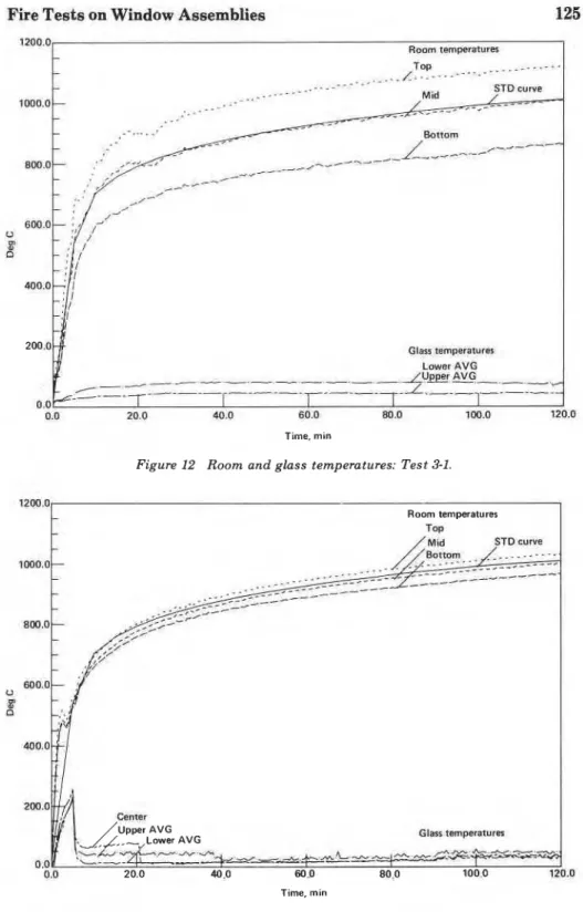
in all tests. Curves are shown in Figure 10 for Test 1-5, in Figure 11 for Test
2-2, and in Figure 12 for Test 3-1. The difference between the curves for the upper and lower thermocouples is primarily the result of steam and water spray from the sprinkler that were drawn back towards the burner in the
lower portion of the room. Figure 13 shows the corresponding room temper-
atures when the sprinkler was located outside the bum room (Test 1-8).
Fire
Figure 10 Room and glass temperatures: Test 1-5.
1200.1) TOP J'...-.-.-
-
.... - -
_.-*-. _.__.. _.--. - -.
.
- Mid STD curve._.-
.-._.
.
.._.-
.
.*1-
----.,/---
.-...____----
Bottom _c-- _--_, /--- 1000.0 Upper AVG Glass mparafures I I I I 0.0 5.0 10.0 15,O 20.0 25.0 30.0 35.0 40.0 45.0 Time, min R mtemperatures fop/
---..,...-.
'--..-
. - - - -- . . ___.._..._..--- Mid STO cuke
.
,._-..--
,....--
Figure 11 Room and glass temperatures: Test 2-2.
-
.
. . -.
...- ,....
-..- , r r _ - _ s - - - ~ p - - A Bottom -J-4./\r/-A-14\/J+-+ --,,--- ----/<-* " ,
d Glass temperatures _._ _ I . - - . I _ _-. center I I 0.0 20.0 40.0 60.0 80.0 100.0 120.0 Time. minFire Tests on Window Assemblies 125 1200.0 ~ o o m temprstures
1
L - _....--- - , _ _ . . - - - . * - . . - .._._.--- STD CUNC 1 m . o - .I- . . ...
I . - - - - .-'-
.
- ... . . Bottom,---
A 0 8: P (31- temperatures L w r AVG -.- - . . - _LUEnvG-. -_----
/ - - --- --- -L.---Z 0.0 4 0.0 20.0 40.0 60.0 80.0 100.0 120.0 Time. minFigure 12 Room and glass temperatures: Test 3-1.
Room temperatures
I
- - STD curve 1mo.o- --
U m.
Gtass temperatures 20.0 40.0 60 .O 80.0 100.0 120.0 Time, minture in line with the standard curve during the latter part (approximately 20 min) of the tests, mainly because of the significantly lower temperature in the bottom of the room. To increase temperatures in the room so that they followed the standard curve, a sheet steel baffle, which directed more of the steam and water spray toward the exhaust stacks, was installed (see Figure 1).
The significance on the fire exposure to the sample of locating the ther-
1 mocouples further away cannot be exactly determined. The thermocouple
readings were representative of the air temperature adjacent to an envelope comprised of the water spray and the glass and not just the glass itself. I t
* must be appreciated, however, that the total heat input to the room (and the
resulting fire exposure to the sample) was approximately 60% higher with sprinklers operating than without in order to compensate for the heat ab- sorbed by the water spray.
Approximately 20 min after the tests using sprinklers had begun, tem- peratures on the unexposed face of the glass reached a reasonably steady state. The average temperature on the lower half of the glass was approxi- mately 30°C higher than on the upper half (see Figures 10 through 12). This is probably because the water absorbed heat as it ran down the glass. The temperatures on the outside of the double-glazed assembly (see Figure 11)
were higher than the temperatures on the single-glazed units (see Figures 10 and 12), since the outer glazing was not receiving the cooling effects of the water from the sprinkler.
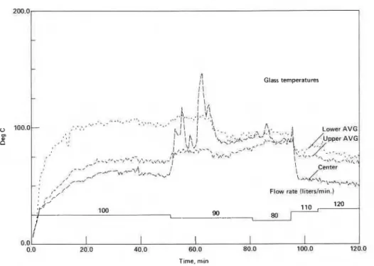
In Tests 1-1, 1-2, and 1-3, water flow rates were varied to determine their effect on glass temperatures on the unexposed face. In these tests, the tem- peratures on the unexposed face rose when the water flow rate was less than 100 Llmin, and tended to stabilize between 65°C and 100°C a t flows greater than 100 Llmin (see Figure 14). Temperatures a t the center of the glass, in particular, tended to increase rapidly with decreases in the water flow rate, as shown by the Test 1-2 results in Figure 13. These results may be at- tributed to the fact that the greater portion of the discharge from the sprin- kler was directed toward the side of the window, so that decreasing the flow prevented the water from reaching and cooling the center of the glass.
In Tests 1-6 and 1-7, in which no sprinklers were used, temperatures of the unexposed glass were significantly higher than temperatures in tests using sprinklers a t the same point in the test. In Test 1-6, average and max-
.
.
imum temperatures for unexposed glass were 260°C and 290°C. respec- tively, when the glass broke a t 6.5 min. At breakage, the temperature a t the center of the exposed side of the glass was 380°C. In Test 1-7, the glass broke a t 5 min when the average temperature was 240°C and the maximum temperature was 260°C. At breakage, the temperature on the lower half of the exposed side of the glass was 290°C.In Test 1-8, in which the sprinkler was located outside the burn room, temperatures of the unexposed side of the glass rose to approximately
Fire Tests on Window Assemblies 127 270°C prior to sprinkler activation. Following sprinkler activation, the tem- peratures rapidly fell, so that the average of the five thermocouples on the
unexposed face was less than 50°C. These thermocouples were exposed to
the water flow from the sprinkler.
FRAME TEMPERATURES
In the steel frame tests in which sprinklers were located inside the burn J
room (Tests 1-1 through 1-5), temperatures on the outside face of the frame
were below 100°C when the water flow rate exceeded 100 Llmin (90
Llminlm). Temperatures as high as 170°C were recorded on the outer frame
.
when the water flow rate was 80 Llmin (72 Llminlm) or less. On the inner
frame, temperatures less than 100°C were recorded, for the most part, when
the water flow rate exceeded 100 Llmin; temperatures increased to 300°C
when the water flow rate was reduced to 80 Llmin. The lower temperatures
noted when the sprinklers were located on the fire-exposed side indicate that frame materials less heat resistant than steel can be used under such condi- tions.
In Test 1-8, in which the sprinkler was outside the burn room, tempera-
tures recorded on the fire-exposed side of the frame were 900°C to 1050°C,
while the temperatures of the outer frame (in contact with the sprinkler
spray) were 20°C to 60°C. If sprinklers are located on the unexposed side,
steel is probably the only material that can withstand such temperatures without failing. n I I Glass temperatures I !
,
100.0- m d 0 0 - 1 \ I I.
.. .
. . 1 ,.
' I I . _ ' , I . - ,- *,., ,-.,-.--
,,~,,.,I'- ,-' ,--' I\
Center , /---w-~~,*-.%~, I-
I / - J - : # ' /,-,,/ Flow rate Il1terslm1n.l
-
' r ,. ,)'r
Ion 1 90 1 1 0 , lZO.
, 8 0 1 I I I 0.0 20.0 40.0 6 0 0 80.0 100.0 120.0 Tlme. min128
I
In the Series 2 tests, in which the aluminum frame was partly protectedby gypsum board on the fire-exposed side, the temperatures of the inner frame (in contact with the water spray) ranged from approximately 20°C a t the top to approximately 60°C a t the bottom. The outer frame temperatures ranged from approximately 45°C a t the top to approximately 70°C a t the bottom. In both tests in this series, frame temperatures reached a steady
I state 20 min after the start of the test.
In the Series 3 test, in which the aluminum frame was fully exposed to fire, the inner frame temperatures ranged from approximately 60 "C to 80" C on the sides and bottom to approximately 150°C a t the top. Because of its location on the frame, the top inside thermocouple was not directly in the water spray, hence the higher temperature. The outer frame temperatures ranged from approximately 20°C a t the top to approximately 70°C on the south side. During this test it was noted that the gasket material a t the top of the window had developed a leak approximately 20 min after the test had begun, causing a water film to run down the center of the unexposed face. This resulted in the low temperatures of the unexposed side of the bottom frame member.
The maximum radiant heat flux transmitted through the windows is given in Table 3. Radiometers were located either a t the midpoint, or a t the midpoint of the top or bottom half of the windows. In the 2-h tests, reasonably steady-state conditions were observed from approximately 60 min after the start of the test until the end.
In Test 3-1, a leak developed in the gasket material a t the top of the win- dow near the centerline. A small amount of water flowed down the outside of the glass, reducing the radiation received by the radiometer.
The radiant heat inside the burn room a t the 2-h point in the fire test is calculated to be approximately 10 Wlcm2. The maximum radiant heat flux measured on the unexposed side of the glass in any test was 0.6 Wlcm2, in- dicating absorption greater than 90% by the water and the glass. This agrees with the results reported in the Australian tests."
Law9 and McGuire'" have both reported that to ignite cellulosic materials (unpiloted ignition), a heat flux of 3.35 Wlcm2 (0.8 callcm21s) is re- quired. The radiant heat flux on the unexposed side of the glass in the tests described here did not exceed 20% of this value. Law9 also reports that a person can tolerate a radiation intensity of 0.59 Wlcm2 for up to 10 s before
- * he feels unbearable pain. This would mean that a person could take up to
10 s to move past a window in a compartment with a fully developed fire where sprinkler protection similar to that used in the tests is installed.
The air pressure inside the burn room in all tests was positive (relative to atmospheric) from the beginning and increased to 25 Pa (above at- mospheric) a t the end of the 45-min test (Test 2-2) and 40 Pa a t the end of
Fire Tests on Window Assemblies
Table 3 Maximum radiant heat flux on unexposed side of glass.
Test Maximum Radiant
Number Heat Flux (W/cm2)
1-4 Top half 0.58 Bottom half 0.52 1-5 Midpoint 0.60 1-6 Midpoint 0.45' 1-8 Midpoint 0.40 2-2 Midpoint 0.44 3-1 Bottom half 0.47
' Occurred at time of glass breakage (6.5 min).
the 120-min tests. In Test 1-8, in which the sprinkler was outside the burn room, the air pressure progressively rose to a maximum of 35 Pa a t the end of the 120-min test. The positive pressure was the result of supply air for the burner, steam generation, the exhaust configuration, exhaust flow resis- tance, and the buoyancy of hot gases inside the room.
Sprinkler activation times are shown in Table 2. In all tests where tempered glass was used, the sprinklers inside the burn room activated early enough to prevent the glass from breaking. In general, the quick- response sprinklers used in the Series 2 and 3 tests responded two to three times faster than the standard sprinklers in Tests 1-4 and 1-5. The fast ac- tivation times recorded in Table 2 for Tests 1-1 through 1-3 were due to a high initial gas input to the burn room, which resulted in a temperature rise more rapid than that specified by the standard time-temperature curve.
When a quick-response sprinkler was placed outside the wired glass in Test 1-8, the response time was 315 s (see Figure 14). At this point in Test 1-8, temperatures for the unexposed glass were in the range where tempered glass failed in Tests 1-6 (average temperature 262°C) and 1-7 (average tem- perature 247°C). The wired glass, although cracked extensively, withstood
the thermal shock following sprinkler activation. In Test 1-7, a 150 X 150
mm sheet steel baffle was placed outside the glass behind a quick-response sprinkler to form a trap for hot air rising along the pane. The sprinkler was
not connected to the water supply. This reduced sprinkler activation time to
,
270 s. Although use of a baffle was not investigated, it may ensure sprinkler activation early enough to prevent tempered glass from breaking. If so,
then tempered-glass assemblies could be protected by sprinklers on the un-
. .
Iexposed face.
Sprinkler water flow rates and water flows per meter of glass pane width are shown in Table 2. In general, varying the water flow rates tended to af- fect the center of the glazing more than the edges and the frames, although minor variations in conditions a t these locations were also noticed.
130 Fire Technology
In the Series 1 tests, the water flow rate required to prevent dry spots
from forming on the glass was 100 Llmin (90 Llmin per meter width) when the sprinkler was located inside the burn room. At this flow rate, steady- state conditions developed on the glass (the temperatures of the unexposed glass ranged from 65°C to 120°C) a t approximately 20 min after the start of each test, as noted in Figure 10 for Test 1-5 (see also Figure 13 for Test 1-2). In Test 1-3 a t a water flow rate of 110 Llmin (100 Llmin per meter width),
:
temperatures of the unexposed glass were in the range of 70°C to 110°Cwhen steady-state conditions were reached. In Test 1-8, in which the sprin- kler was located outside the burn room, the radiation transferred through the glass tended to increase when the water flow rate was reduced to 60 Llmin (55 Llmin per meter width) or lower. In this test, no significant in- crease in temperature on the unexposed face was noted with decreasing water flows.
In the Series 2 tests, the water flow rate required to prevent dry spots on
the inner glass surface was found to be 110 Llmin (74 Llmin per meter width). The thermocouples were located on the outside of the outer pane of the doubleglazed unit, and as such the temperatures of the unexposed glass did not show much variation with changing water flow rates on the exposed glass (inner pane).
In the Series 3 test, it was found that the water flow rate required to keep dry spots from forming was 115 Llmin (68 Llmin per meter width). With lower flows, dry spots were observed on the center portion of the ex- posed side of the glass.
Following Test 3-1, the unexposed face of the tempered-glass assembly was subjected to a nonstandard hose-stream test, as described previously. I t differed from the standard tests due to the fact that the standard hose- stream test equipment was not available and that the test wall could not be removed from the test apparatus to enable the exposed sample face to be subjected to the hose stream. While the flow rate of the nozzle used (473 Llmin) was less than that required in the standard (784 Llmin), the in- creased velocity due to the increased nozzle pressure (690 kPa versus 205 kPa) gave a momentum that is approximately the same as the standard hose stream.
The tempered glass did not break, and no damage was caused to the frame as a result of the described hose-stream test. Since the glass tempera-
- 1 tures in all tests were low, it is anticipated that any wired- or tempered-
glass assembly protected by sprinklers on the fire-exposed face, as de- scribed, could survive the standard hose-stream test.
During the tests in which the sprinklers were inside the burn room, a greater-than-expected quantity of fuel was needed to maintain the standard time-temperature curve. Assuming 100% combustion efficiency, the
Fire Tests on Window Assemblies 131
estimated heat-release rate when the sprinkler was inside the burn room was approximately 4 MW during the last minutes of the 2-h tests. When the sprinkler was outside the burn room, the estimated heat release rate during the last minutes of the 2-h test was approximately 2.5 MW.
CONCLUSIONS
From these series of experiments, the following conclusions were drawn. These conclusions relate to the glazing systems and sprinkler arrangements ' tested and should not be construed as being representative of other situa- tions, unless noted.
1. The glazed assemblies protected by sprinklers, as described, will .I withstand a fire exposure approximating that provided by the stan- dard time-temperature exposure; for a t least 2 h for single-glazed assemblies, and a t least 90 min for double-glazed assemblies. Since the assemblies did not fail a t those times, durations greater than those tested can realistically be expected.
2. The level of radiation transmitted through the protected glazed assemblies is not sufficient to ignite (unpiloted ignition) ordinary combustible materials adjacent to the unexposed side, or to cause unbearable pain to a person moving past the window in less than 10 s.
3. The temperatures measured on the unexposed face of assemblies in which sprinklers were located on the fireexposed side are within the range permitted by CAN4-S101-1981.8
4. The glazed assemblies, as described, cooled by sprinklers on the fire- exposed side, can withstand a nonstandard hosestream test follow- ing fire exposure.
5. When sprinklers are installed on the fire-exposed side, both quick- response and standard sprinklers respond in sufficient time to pre- vent tempered glass from breaking when the sprinkler is activated. In the case of sprinklers installed on the unexposed face, it is not known whether even quick-response sprinklers can activate quickly enough to prevent tempered glass from breaking upon sprinkler ac- tivation, unless other means are provided to reduce sprinkler response time.
6. Wired glazed assemblies in steel frames can withstand the described
;.
fire exposure for a t least 2 h, whether sprinklers are installed on theI
fire-exposed or unexposed side. I
7. Minimum sprinkler water flow rates to prevent dry spots from form-
-
'
ing on the glass appear to be 70 to 80 Llmin per meter width, butlower flow rates may provide sufficient protection.
8. Sprinkler water distribution to the center portion of the glass ap- pears to be a t least as critical as distribution to the sides to prevent dry spots from occurring.
9. The heat input required to maintain the standard timetemperature curve in the burn room (measured 1.4 m from the sample) when a
sprinkler is located on the fire-exposed side, as described, is approxi- mately 60% greater than when a sprinkler is located outside the burn room.
10. Aluminum and steel frame materials behave similarly (with respect to warping and distortion) when sprinklers are located on the fire exposed side.
t 11. Tempered-glass assemblies with areas greater than 5 times and
dimensions greater than 1.8 times the wired-glass specifications in
the National Building Code of Canada are able to withstand a fire ex-
? posure approximating the standard fire exposure for a t least 2 h
when sprinklers are located on the fire-exposed side, as described.
12. Radiated heat flux levels are reduced by more than 90% by the win-
dow sprinkler systems used in these tests.
As with all fire protection measures, the designer must realize the limita- tions of this protection system to ensure its proper use. One system under specified conditions has been described. Details such as pane size, location and response time of sprinklers, water flow rates, frame materials and mounting techniques, and water distribution over the glass have been iden- tified as most important factors and must be carefully assessed prior to utilizing a window sprinkler system.
ACKNOWLEDGEMENTS: The authors wish t o thank Rolf Jensen and Associates Ltd. for their permission t o use the information gathered from tests performed under contract to them, and Grinnell Fire Protection Systems Co. Ltd. for providing the sprinkler installations. The authors appreciate the assistance of J. E. Berndt, D. W. Carpenter, G. P. Crampton, V. Fort-
I
ington, and M. Ryan a t the National Fire Laboratory in the design, installation, execution and analysis of these tests.REFERENCES
' The National Building Code of Canada. Associate Committee on the National Building Code, National Research Council of Canada, Ottawa. 1985.
"Fire-Resisting Glazing - Clear Borosilicate Glass," FPA Information Sheet B17, Fire Protection Association, London. January 1985.
' Malcomson, R. W., "Report on Window Sprinkler Systems," Underwriters Laboratories Inc., Report No. NC529, Northbrook, IL. July 1969.
' Moulen, A. W. and Grubits, S. J.. "Water Curtains t o Shield Glass from Radiant Heat from Building Fires," Technical Record 4411531422, Experimental Building Station, Depart- ment of Housing and Construction. Australia, July 1975.
' Moulen, A. W. and Grubits. S. J., "Water Drenching of Tempered Glass Used t o At-
- ' tenuate Radiant Heat," Technical Record 498, Experimental Building Station, Department of
Housing and Constuction, Australia, July 1983.
"erguson, A,. "New Standards for Atrium Building," Fire Prevention, No. 184, London, November 1985.
- I ' Deutsches Institut fiir Normung Report 4102, Part 3, "Fire Behavior of Building
Materials -and Building Components; Fire Walls and Non Load Bearing External Walls; Definitions, Requirements and Tests." Deutsches Institut fiir Normung, 1977.
Standard Methods of Fire Endurance Tests of Building Construction and Materials (CAN4-S101-M82), Underwriters' Laboratories of Canada, Toronto, December 1982.
Law, M., "Safe Distances from Wired Glass Screening a Fire," I.F.E. Quarterly. Vol. 29, No. 73, March 1969, pp. 62-70.
'" McGuire, J. H ., "Ignition of Materials behind Common 118-inch Thick Window Glass," Technical Note 456, Division of Building Research, National Research Council of Canada, Ot- tawa, September 1965.
T h i s p a p e r i s being d i s t r i b u t e d i n r e p r i n t form by t h e I n s t i t u t e f o r Research i n C o n s t r u c t i o n . A l i s t of b u i l d i n g p r a c t i c e and r e s e a r c h p u b l i c a t i o n s a v a i l a b l e from t h e I n s t i t u t e may be o b t a i n e d by w r i t i n g t o t h e P u b l i c a t i o n s S e c t i o n , I n s t i t u t e f o r R e s e a r c h i n C o n s t r u c t i o n , N a t i o n a l Research C o u n c i l of C a n a d a , O t t a w a , O n t a r i o , K 1 A 0R6.
Ce document e s t d i s t r i b u 6 sous forme de t i r e - 3 - p a r t p a r l 1 1 n s t i t u t de r e c h e r c h e e n c o n s t r u c t i o n . On peut o b t e n i r une l i s t e d e s p u b l i c a t i o n s de 1 ' I n s t i t u t p o r t a n t s u r l e s t e c h n i q u e s ou l e s r e c h e r c h e s e n matisre d e b l t i m e n t e n C c r i v a n t


![Risiko- & [und] Schutzfaktoren der psychischen Gesundheit humanitärer Einsatzhelfer : eine systematische Literaturübersicht](data:image/gif;base64,R0lGODlhAQABAIAAAP///wAAACH5BAEAAAAALAAAAAABAAEAAAICRAEAOw==)