Publisher’s version / Version de l'éditeur:
Vous avez des questions? Nous pouvons vous aider. Pour communiquer directement avec un auteur, consultez la première page de la revue dans laquelle son article a été publié afin de trouver ses coordonnées. Si vous n’arrivez pas à les repérer, communiquez avec nous à PublicationsArchive-ArchivesPublications@nrc-cnrc.gc.ca.
Questions? Contact the NRC Publications Archive team at
PublicationsArchive-ArchivesPublications@nrc-cnrc.gc.ca. If you wish to email the authors directly, please see the first page of the publication for their contact information.
https://publications-cnrc.canada.ca/fra/droits
L’accès à ce site Web et l’utilisation de son contenu sont assujettis aux conditions présentées dans le site LISEZ CES CONDITIONS ATTENTIVEMENT AVANT D’UTILISER CE SITE WEB.
Building Research Note, 1985-11
READ THESE TERMS AND CONDITIONS CAREFULLY BEFORE USING THIS WEBSITE.
https://nrc-publications.canada.ca/eng/copyright
NRC Publications Archive Record / Notice des Archives des publications du CNRC :
https://nrc-publications.canada.ca/eng/view/object/?id=9d711d63-653f-4e1c-aec0-ee5286700444 https://publications-cnrc.canada.ca/fra/voir/objet/?id=9d711d63-653f-4e1c-aec0-ee5286700444
NRC Publications Archive
Archives des publications du CNRC
This publication could be one of several versions: author’s original, accepted manuscript or the publisher’s version. / La version de cette publication peut être l’une des suivantes : la version prépublication de l’auteur, la version acceptée du manuscrit ou la version de l’éditeur.
For the publisher’s version, please access the DOI link below./ Pour consulter la version de l’éditeur, utilisez le lien DOI ci-dessous.
https://doi.org/10.4224/40000482
Access and use of this website and the material on it are subject to the Terms and Conditions set forth at
DBR's approach for determining the heat transmission characteristics
of windows
Ser Tm ~ 9 2 no, 234 c , 2 3m
National Research
Comeif
nat tonalI
$
Council
Canada de recherches CanadaDivision of Division des
BuildingResearch recherchesenbitirnent
Building Research
Note
DBR's
Approach for Determining
the
Heat
Transmission Characteristics of Windows
by
R.P.
Bowen
BRN 234
A N A L Y Z E D N R C-
C I - T I#DG,
R6S. L I B R A R YDBR'S APPROACH FOR
DETERMINING THE
HEAT TRANSMISSION
CHARACTERISTICS
O FWINDOWS
by
R.P.
Bowen
Building
ServicesSection
Division
of
Building
Research
BRN
234ISSN
0701-5232Ottawa, November 1985
TABLE OF CONTEHTS
A B S T R A C T I R ~ S U M ~ INTRODUCTION
BACKGROUND
THEORY
PROBLEMS WITH CONVENTIONAL CALORIMETER FOR WINDOW TESTING
DBR WINDOW CALORIMETER Calibration
SLIMMART
ABSTRACT
Current standard hot box techniques for determining the thermal
conductance o f w a l l s are not adequate Tor u s e with windows. T h i s report discusses t h e problems with testing windows and presents the Division of Bulldlng Research window calorimeter designed to reduce the errors
associated w i t h determining calorimeter enclosure surface temperature and air temperatuie.
Ies techniques de chambre chaude normalis&es actuelles qui servent 3
dsterminer la conductance thermique des murg ne conviennent pas dans le cas
des fe&tres. k prgsent r a p p o r t examfne la question des essais de fenetres
ec dgcrit le ealorimStre pour fenetres de la Division des recherches en
Mtiment, appareil d e s t i d 3 ri5duire les erreurs associgee
a
la tempgratureThe Division of Building Research of the National Research Quncil of Canada (DBBINRCC) has for nrany gears supported an on-going program to study the thermal performance of wtndows. Early work concentrated on surface temperature performance as it relates to window condensation, but as energy costs have increased attention has been d i r e c t e d towards heat transmission characteristics, DBR, using a window calorimeter it developed for its environmental test f a c i l i t y , is working on a heat transmission or thermal resistance t e s t for windows.
This report discusses t h e development of the DBR window calorimeter and the test procedure, i n whfch is calculated an equivalent surface temperature
that is used to d e t e r d n e the coefficient of heat transfer between i n s i d e
and outside specimen surfaces. Experience in applying this procedure, using
a calorirrteter designed for w a l l s , facilitated t h e design of a wkndow calorimeter incorporating a uniform temperature b a f f l e and convection
heater. Calibration of the w b d o w calorimeter is discussed and an example c,alculation is given.
Information on the thermal performance of windows is required for two
main reasons:
to assist designers t o p r e d i c t heat losses,
to provide a ranking of windows for thermal comparison.
For the f i r s t category the t e s t would have to b e complex and i n c l u d e
factors a f f e c t i n g heat transmission, i.e., temperature, solar incidence, wind, room-ide air m o v e ~ n t
,
air leakage, etc, Such an evaluation would bevery expensive. The second category, which is of immediate interest, is
designed to provide a ranking of products in the laboratory that would be similar to the ranking expected in the field. The procedure could be standardited to ensure that the values from different f a c i l i t i e s are
comparable.
It
would allow for comparison of different windows, as well asassessment of thermal improvement I n a parrlcular window system.
For ranking purposes windows can be described by t h e i r U-value, which i s the overall coefficient of heat transfer (air to air), or by their C - v a l u e , which is the coefficient of heat transfer between i n s i d e and
outside surfaces. There are a number of test methods that c l a i m to measure
Uyalues of high c~nductance specimens such as windows: ASTM C236, Standard T e s t Method for Steady-State Thermal Performance of Building Assemblies by Heans of a Guarded Hot Box; ASTH C976, Standard T e s t Method f o r Thermal
Performance of Building Assemblies by Means of a Calibrated Hot Box;
AAHA 1503.1, a methad developed by the Architectural Aluminum Manufacturers Association. The two ASTM standards include a C-value calculation based on
surface temperature measurements and area weighting. Because measurements
of temperature on glass and area weighting are not very accurate, DBR is
developing an alternatfve approach for establishing C-walues for windows. This procedure involves calculating a room-side equivalent surface
temperature for the specimen by means of the r a d i a t i v e and convective
specimen surface temperature is a l s o calculated using the specimen heat f l o w and the w e a t h e r s i d e surface f i l m resistance. The characteristics of the
calorimeter and w e a t h e r s i d e surface film mst first be established by calibration tests (discussed later) , This procedure was developed by
Solvason et al. (1) in t h e early 1960s for determining the equivalent i n s i d e surface temperature of noa-isotropic walls.
The benefits of the DBR procedure for calculating a C ~ a l u c are:
1) it is possible to compare results from dffferent lahratories. As exact repeatabflfty of the a i r f i l m s produced by different t e s t f a c i l i t i e s is not required, the a i r films can be s p e c i f i e d wlthin broad limits,
Emphasis is p l a c e d on calibration of equipment over a range of heat flows and specimen sizes t o define the f a c i l z t y characteristics.
2) the uncertainty introduced by using thermocouples t o measure glass and frame temperatures to be used in calculating an area-weighted average
surface temperature is eliminated.
Radiant heat exchange among various surfaces w i t h i n t h e calorimeter and on the specimen surface i s accounted for in order to increase accuracy of C-value determination.
A design U ~ a l u e used for product comparison can be c a l c u l a t e d using
standard values for the inside and outside air films.
R O O M S I D E Troom
=
T,, *T 1 DC WWEA 1 NPUT S W l E S T f W E POLYSNREM SVRROUM W E A J H E R S I D E F i g u r e 1. Calorimeter boxIn summary (2), t h e approach involves
measuring the total power s u p p l i e d to the calorimeter and deducting the heat transfer through the mask ( a -
support wall of known properties) t o
arrive at the heat transfer through the specimen. F r o m the specimen heat
transfer, using the relations for radiative and convective heat tranfer
from the talorimeter to the specimen,
the equivalent room-side surface
temperature of the specimen can be calculated. The equivalent
weather-side surface temperature is also calculated from the specimen
heat transfer and the a i r f i l m provided by the DBR wfnd machine. The thermal conductance, resistance, design thermal resistance, and d e s i g n coefficient of heat transmission are
then calculated.
The thermal analysis of specimens mounted in a support wall (mask) placed between a weather-side and a room-side chamber i s based on the heat
where QT = t o t a l power supplied t o calorimeter
%
= heat flow through calorimeter box walls (controlled so as to beof negligible value)
9,
= heat flow through the mask (function of surfac.e temperatures andmask conductance)
Qe = flanking loss amund the edge of the specfmen
Q, = heat flow through the specimen.
Noting t h a t Qg is equal to t h e heat flow through the surface of the specimen, it may be expressed as
where Qr = radiant heat exchange between calorimeter surfaces and roomafde
surface of the specimen, and
p,
= convective heat exchange between calorimeter d r and room-side surface of the speciu~en,In a grey enclosure the radiation exchange between two surfaces can be expressed as:
where
A1
= area of surface 1= overall interchange factor for radiation from surface 1 to surf ace b
Fis = Stefan-Bolteman canstant*
Tb = absolute temperature of surface b (calorimeter b a f f l e )
TI = absolute temperature of surface 1 (specimen). The convection component is approximated by
where Th = the absolute temperature of the air in the calorimeter box, and 3
and C are constants to be determined from calibration tests, Equations 3
and 4 can be approximated by:
As the r a d i a t i v e and convective heat flow paths are parallel, the sum of the two coefficients, hr and h,, is t h e roonrsidc combined heat transfer
coefficient (air film) for the configuration under test,
.
If Th was expressed as:equivalent t o Tb, the total heat transfer t o and through e specimen can be
The w e a t h e r s i d e air f i l m , fo, is:
where T2 = calculated weather-side surface temperature
Tc = weather-side a i r temperature.
Figure 2. DEB wind machine
The above calculations are based on the assumption that over t h e range of weather-side temperatures to be used the DBR w5nd machine (Figure 2) generates a relatively constant f , and the radiating temperatures are
equivalent t o Tc. The test specimen conductance., C, and resistance, R, are
For c o . q a r i s o n , a design thermal resistance value,
RD,
can be obtained by the addition of standard surface film resistances, Rfi and Kf,, to the specimen t h e m 1 resistance value R:The design U v a l u e is then I / R ~ .
P B O B M S WITH COHVENTIOBIBL CALORIMETER FOR W f b l D W T E S T S
Using the a b v e approach and the DBR calorimeter designed for walls, a t e s t series was undertaken to evaluate the thermal. performance of sealed
glazing units. T h i s indicated that the wall calorimeter design is not:
s u i t a b l e for window t e s t i n g - The main problem is i t s i n a b i l i t y to maintain
a uatform and definable calorimeter enclosure surface temperature and air
temperature. The heat transfer through the window r e l a t i v e to the mask causes the calorimeter surfaces t o be c o l d e r than Th and both Tb and Th to be non-unif orm.
DBR WINDOW CdLQEIlfET;$B
This calorimeter, designed specifically t o measure the heat transmission characteristics of mlndows, has the following features:
-
uniform temperature baffle to g i v e a uniform Tbuniform temperature convection heater to improve the uniformity of =ha
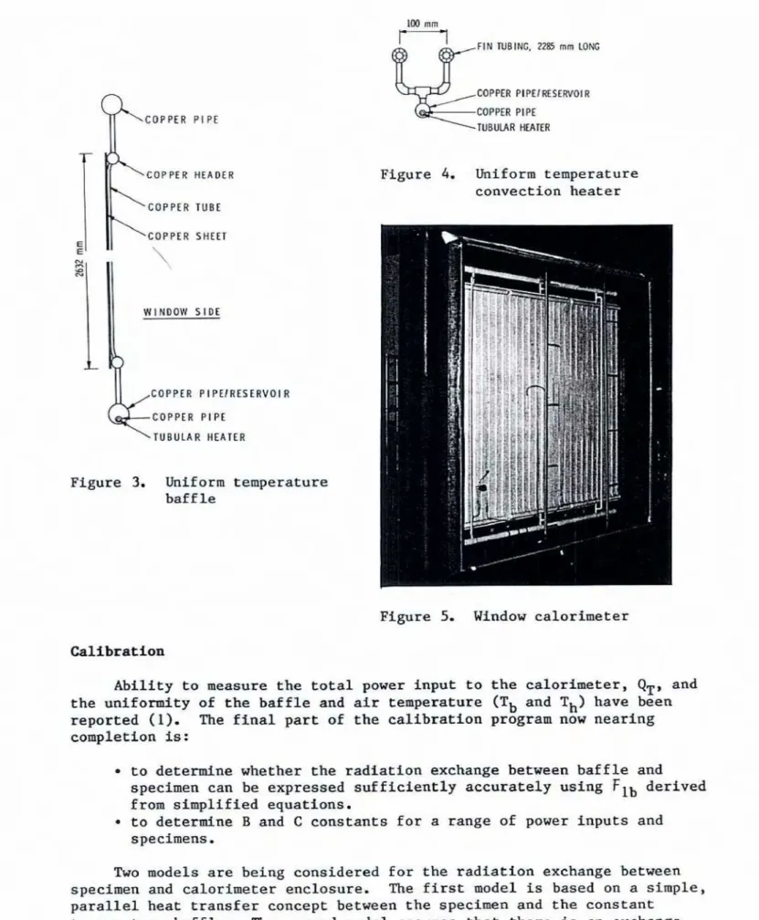
An eveporatlng/cmdensing panel using refrigerant R-12 was designed to
provide a udform temperature on t h e baffle (Figure 3). A tubular heater
for b o i l i n g the refrigerant is contained in a p i p e resemoir connected to
the panels.
The uniform-temperature convection hearer was a l s o obtained by
evaporating and condensing 8-12 (Figure 4).
It
w a s constructed of two f i n tubes connected to a copper pipe reservoir containing a second tubularheater of the sane power rating, far s i m p l i c i t y , as that i n the baffle. The constant-temperature b a f f l e and convection heater were i n s t a l l e d in the
Ukl mrn
-
COPPER P i PE C O P P E R HEADER C O P P E R TUBE E C O P P E R SHEET E \ \ WINDOW S I D Eb
COPPER COPPER P I P E I R E S PIPE ERYOI RFigure 3. Unif o m temperature b a f f l e -
FIM TUB IN. 22@ mm LOW
COPPER PIPE!IIESEAVOlR
COPPER PlPE
Figure 4. h i f o r m temperature
convection heater
Figure 5, Window calorimeter
Calibration
A b i l i t y to measure the total power input to t h e calorimeter, QT, and the uuiformity of the b a f f l e and air temperature (Tb and Th) have been reported (1). The f i n a l part of the c a l i b r a t i o n program now nearing completion is:
t o determine whether the radiation exchange between baffle and
specimen can be expressed s u f f i c i e n t l y accurately using
fib
derivedfrom simplified equations.
t o determine B and C constants for a range of power inputs and specimens
.
Two models are being considered for the radiation exchange between
specimen and calorimeter enclosure, The first model is based on a simple,
parallel heat t r a n s f e r concept between the specimen and the constant temperature b a f f l e . The second model assumes that there is an exchange among a l l surfaces of the enclosure and specimen. The l a t t e r is a more
accurare model of t h e radiation exchange within the calorimeter enclosure,
hut it requires more d e t a i l e d analysis.
For the f i r s t model,
Fib
is represented bywhere el, eb = emissivities of the specimen end b a f f l e , A l , Ab = area of the specilaen and baffle.
The second model uses programs developed by Mtalas and Stephenson ( 3 ) to calculate radianz energy interchange factors for the calorimeter
enclosure, These factors are used in the following to calculate q,:
and
where Ti = absolute temperature of surface I , and
Fli
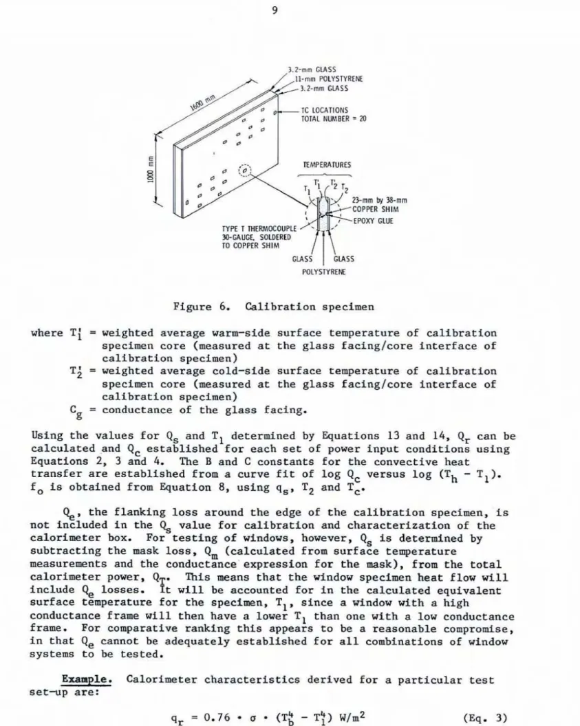
= interchange factor for surface 1 to surface i.For calibration t e s t s using the s p e c h e n shown in Figure 6 , Qs is determined from the following
where A, = area of calibration specimen
C, = conductance of calibration specimen core
ATc = measured temperature drop across t h e calibration specimen core.
The surface temperatures, T1 and T2, f o r the calibration tests are
3.2-m MASS E E RMPEWTURES
El
r \ W E T TWRWE0UPl.E SOLDERED TO COPPER SHIMFigure 6. Calibration specimen
where Ti = weighted average warm-side surface temperature of calibration specimen core (measured at the glass facfnglcore interface of calibration specimen)
Ti = weighted average cold-side surface temperature of calibration
specimen core ( ~ a s u r e d at the glass facinglcore interface of
calibration specimen)
Cg = conductance of the glass facing.
Using the values for Q, and T1 determined by Equations 13 and
14,
Q, can be calculated andQ,
established for each set o f power input conditions usiqgEquations 2, 3 and 4. The H and C constants for the mrivcctive heat transfer are established from a curve fit of log Q, versus log (Th
-
TI). f, is obtained from Quation 8, using q,, Tz and T,.%,
the flanking loss around the edge of t h e calibratfon specimen, isnot: included in the Q8 value for calibration and characterization of the
calorimzter box. For testing of wtndows, however, C& i s determined by subtracting the mask loss, Q, (calculated from surface temperature
measuremnts and the conductance'expression for the
m s k ) ,
from the total calorimter power, Q T m This means that the window specimen heat flow w i l l include losses. It will be accounted for in the calculated equivalent:surface temperature for the specimen, TI, s i n c e a window with a high
conductance frame w i l l then have a lower TI than one with a l o w conductance frame. For comparative ranking t h i s appears to ke a reasonable compromise,
in that Q, cannot be adequately established for all combinations of wfndow systems t o be tested.
m Z e . Calorimzter characteristfcs -derived for a particular test o e t v p are:
Measured values:
QT = 260 U
A1 = 1.605 rn2
Calculations:
Solving the a b o n three equations for q,, q, and TI y i e l d s q c = 59.2 w/m2
- 66.8 w/m2 Qr
-
TI = 279.1 K ( 5 . 9 0 ~ )
By Quations 5 and 6 , therefore
h, = qr/(Tb
-
TI) = 66.8/(295.4-
279. I ) = 4.10 w / ( r n 2 m ~ ) h, = qC/(Th-
T1)
= 59.2/(295.0-
279.1)-
3.72 w/(m2*~) so that f i = h,+
h, = 7.82 w/(mZ-~).Using the weatherside air f i l m , T2 may be calculated by means af Equation 8:
The t e s t specimen conductance or C ~ a l u e can now be calculated by means of Equation 9:
C-value = q,/(T1-T2) = 126/(279.1
-
2 5 8 . 0 ) C-value = 5-97 w/(~~.K)Fox comparison, a d e s i g n U y a l u e , UD, and d e s i g n thermal resistance value, RD, can be defined by addfng standard ASBRAE air films and calculated as follows :
Current standard hot box techniques for determining the thermal
conductance and resistance of w a l l s are not adequate for use w i t h windows. Measuring glass and frame temperatures for use in calculating a weighted average surface temperature for the window is impractical. Determination of
laboratory U-values f o r windows does not recognize that t h e surfaces of the
calorimeter w f l l be colder than the air temperature, so that a s i n g l e a i r temperature cannot: properly describe the heat transfer t o the window.
The Division of B u i l d i n g Eksearch earlier d e v e l o p e d a procedure for determining the thermal conductance and resistance of non-isotropic walls
that is now being a p p l i e d t o windows. A calorimeter designed specifically
for windows reduces the errors associated with determining calorimeter enclosure surface temperature and a i r temperature.
1. Brown, W.P., K.R. Solvason and A.G. Wilson, A Unique Hot-Box Cold-Roonr
Facility, ASHRAE Transactions, Vol. 67, 1962, p. 561-577.
2. Bowen, R.P. and
LR,
,%lvason, A Calorimeter for Ikrermining Beat Transdssion Characteristics of Uindows,ASTM
Conference on Thermal Insulation, Haterials and Systems, Dallaa, 1984.3. Mitalas, G.P. and D.G. Stephenson, Fortran IV Programs to Calculate
Radiant Energy Interchange Factors, Hational Research Council of Cauada,