Accelerating New Product Deployment with
Manufacturability Guidelines
by
Wern-Lirn Wang
M.S. Chemical Engineering
Pennsylvania State University (1986) Submitted to
the Alfred P. Sloan School of Management
and the Department of Materials Science and Engineering in Partial Fulfillment of the Requirements for the Degrees of
Master of Science in Management and
Master of Science in Materials Science and Engineering in conjunction with the Leaders for Manufacturing Program
at the
MASSACHUSETTS INSTITUTE OF TECHNOLOGY May 1994
© Massachusetts Institute of Technology, 1994
ALL RIGHT RESERVED
Signature of Author
Certified by
Certified by
Accepted by
-M1riSloan School of Manage ý Department of Materials Science and Engineering May, 1994
Deborah Ancona, Thesis Supervisor Ase~ te Professor of Organization Studies
Don P. C , Thes u sor Bernard M. Gordon Professor of Engineerin[t 1ov a ioI(nd4aractice
d11
IJeffrey A. Barks
Associate Dean, Sloan Master's and Bachelor's Programs Accepted by
g
•rlncnp
Carl V. Thompson II, airmanMASSACHUSETrS Q partmental Committee on Graduate Students
a E
.-
-2-Accelerating New Product Deployment with Manufacturability Guidelines
by
Wern-Lirn Wang
Submitted to the Alfred P. Sloan School of Management and the Department of Materials Science and Engineering
on May 6, 1994, in Partial Fulfdllment of the Requirements for the degrees of Master of Science in Management
Master of Science in Materials Science and Engineering Abstract
A manufacturability guidelines approach is employed in this research to accelerate
new product deployment process of thin-film-head. The design-lead product development practices in this industry suggest a traditional design rules approach is inadequate. The manufacturability guidelines take into account the dynamics between design and
manufacturing activities. Through enhancing constructive interactions between design and manufacturing engineers, these manufacturability guidelines render product designers flexibility to explore product technology envelope while ensure the manufacturability of the designs. The guidelines is a knowledge database linking design parameters with manufacturability issues. With their knowledge structure based on physical phenomena of the manufacturing process, the manufacturability guidelines provide likely directions for disciplined design decisions even though the knowledge involved is not thoroughly verified. This research proposed an application of the manufacturability guidelines as a vigilant information system in the design review process. It was also found that the guidelines can be used as a communication tool to facilitate concurrent engineering.
Several organizational and cultural issues were found to be the obstacles for applications
of the guidelines. An organization that promotes information sharing and organizational learning is essential for the manufacturability guidelines to deliver their full potentials. Engineering resources allocation was a concern among the management for a full scale design and manufacturing integration. A pilot product development team approach was then suggested to disseminate experience of team-based product deployment process and rally support from the rest of the organization and upper management.
Thesis Supervisors: Professor Deborah Ancona
Associate Professor of Organization Studies Professor Don P. Clausing
Bernard M. Gordon Professor of Engineering Innovation and Practice
Thesis Reader: Professor Stuart Brown
Associate Professor of the Department of Materials Science and Engineering
-4-Acknowledgment
This thesis would not have been possible without the help and encouragement of several people. Mr. Arthur L. Keigler guided me through the study of thin-film-head
manufacturing process and provided constant support for my work. I would like to thank Mr. Mike Collver and Mr. Larry Neumann for their support and suggestions which have become a integral part of this thesis.
The support and cooperation from people of Mr. Arthur's and Mr. Neumann's groups are specially appreciated. It would be impossible for this research to proceed without the patience and helps from many people in the organization.
The guidance of my faculty advisors, Prof. Deborah Ancona and Prof. Don P. Clausing, has helped me throughout the internship and the preparation of this thesis. I like also to thank for the support of my thesis reader, Prof. Stuart Brown of the Department of Materials Science and Engineering for his special attention on the technical part of this thesis.
Finally, I would like to dedicate this thesis to my wife, Vicki, who have encouraged me through my two years at the Leaders for Manufacturing Program.
TABLE OF CONTENTS
1. INTRODUCTION 13
PART I SMART HEAD BUSINESS (SHB)
2. BACKGROUND 21
2.1 THIN-FILM-HEAD INTRODUCTION 21
2.2 DISK DRIVE AND DISK DRIVE HEAD INDUSTRY 26
2.3 SMART HEAD BUSINESS' MARKET POSITION 30
2.4 CHALLENGES IN NEW PRODUCT DEPLOYMENT 33
3. TFH WAFER PRODUCT DEPLOYMENT PROCESS 35 3.1 OLD PRODUCT DEPLOYMENT PROCESS 35
3.2 REORGANIZATION 39
3.3 NEW PRODUCT DEPLOYMENT PROCESS 41
3.4 CURRENT ISSUES IN PRODUCT DESIGN 45
3.5 CURRENT ISSUES IN NEW DESIGN MANUFACTURING 47
3.6 CURRENT ISSUES IN VOLUME PRODUCTION 49
3.7 THE SCOPE OF THIS RESEARCH 50
PART H TECHNICAL ISSUES
4. MANUFACTURABILITY ISSUES OF TFH WAFER MANUFACTURING 53
4.1 WAFER MANUFACTURING PROCESS 53
4.2 PHOTORESIST COATING 57
4.3 PHOTORESIST PATTERNING 65
4.4 PHOTORESIST HARD-BAKE 69
4.5 REGISTRATION 72
4.6 PHOTORESIST NOTCHING 74
5. DESIGN FOR MANUFACTURING 79 5.1 DESIGN-PUSH VERSUS DESIGN FOR MANUFACTURING 79
5.2 CURRENT MISMATCH BETWEEN PRODUCT DESIGN AND MANUFACTURING
PROCESS CAPABILITY 81
5.3 INTEGRATION OF DESIGN AND MANUFACTURING 85
6. MANUFACTURABILITY GUIDELINES 89
6.1 A KNOWLEDGE ISSUE 89
6.2 THE PROCESS OF DERIVING MANUFACTURABILITY GUIDELINES 92
6.2.1 Process Characterization 92
6.2.2 Fault Tree Analysis 92
6.2.3 Critical Design Parameters 97
6.2.4 Critical Design Parameter Database 97
6.2.5 Manufacturability Guidelines 98
PART III MANAGERIAL ISSUES
7. APPLICATIONS OF THE MANUFACTURABILITY GUIDELINE 99
7.1 A TOOL FOR DESIGN REVIEW 99
7.1.1 Design Review 99
7.1.2 A Tool for Design Review 101
7.1.3 A Model 106
7.2 CONCURRENT ENGINEERING 109
8. IMPLEMENTATION OF MANUFACTURABILITY GUIDELINES
APPLICATIONS 115
8.1 RESISTANCE OVER IMPLEMENTATION 115
8.1.1 The Resistance 115 8.1.2 The Hypothesis 116 8.1.3 The Survey 117 8.1.4 The Conclusion 120 8.2 ORGANIZATION DYNAMICS 122
-8-9. PRODUCT TEAM APPROACH 127
9.1 PRODUCT DEPLOYMENT PROCESS INTEGRATION WITH CONCURRENT
ENGINEERING 127
9.2 PRODUCT DEVELOPMENT TEAM APPROACH 130
9.2.1 Team Definition 130
9.2.2 Product Development Team in SHB 133
9.2.3 The Pilot Team Approach 136
10. SUGGESTIONS FOR FUTURE STUDY 139
10.1 FURTHER REFINEMENT AND UPDATES OF THE MANUFACTURABILITY
GUIDELINES 139
10.2 OTHER GUIDELINE FOR DESIGN PURPOSES 141
10.3 ORGANIZATIONAL STUDY 143 APPENDIX A 145 APPENDIX B 151 APPENDIX C 155 APPENDIX D 157 APPENDIX E 159 REFERENCE 165
LIST OF FIGURES
FIGURE 2-1: FIGURE 2-2: FIGURE 2-3: FIGURE 3-1: FIGURE 3-2: FIGURE 3-3: FIGURE 4-1: FIGURE 4-2: FIGURE 4-3: FIGURE 4-4: FIGURE 4-5: FIGURE 4-6: FIGURE 4-7: FIGURE 5-1: FIGURE 5-2: FIGURE 5-3: FIGURE FIGURE 6-1: 6-2:TFH MAGNETIC WRITING AND RECORDING PROCESS HARD DISK DRIVE MARKET SHARE OF 1992
TFH OEM MARKET SHARE
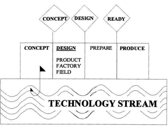
OLD PRODUCT DEPLOYMENT PROCESS
NEW PRODUCT DEPLOYMENT PROCESS
SYSTEM DYNAMICS VIEW OF THE ISSUES A TYPICAL TFH STRUCTURE
TFH DEVICE TOPOGRAPHY
DEVICE ORIENTATION VERSUS PHOTORESIST FLOW COIL PATTERNING AND FOCAL OFFSET
SHADOWING EFFECT
IMPACT OF FEATHERING SCHEME ON SHADOWING EFFECT NOTCHING MECHANISM
MISMATCH BETWEEN DESIGN AND MANUFACTURING REDUCING THE GAP BETWEEN DESIGN AND
MANUFACTURING
SYSTEM DYNAMICS VIEW OF DESIGN AND MANUFACTURING INTERACTIONS
FAULT TREE ANALYSIS
AN EXAMPLE OF FTA
--FIGURE 7-1: A DESIGN REVIEW MEETING 100
FIGURE 7-2: REINFORCING LOOP THAT CAUSES DISINTEREST 103
FIGURE 7-3: CONCURRENT PROCESS 112
FIGURE 7-4: A MODEL OF CONCURRENT ENGINEERING 114
FIGURE 8-1: SHIFTING ENGINEERING RESOURCES TO DESIGN ACTIVITY 123
FIGURE 8-2: A SYSTEM DYNAMIC MODEL 124
FIGURE 9-1: A MODEL FOR INTEGRATED PRODUCT DEPLOYMENT
PROCESS 128
-12-CHAPTER
1. INTRODUCTION
A thin-film-head (TFH) is a miniature electromagnet transducer mounted on a computer
disk drive to record or to reproduce digital signals with magnetic media. With disk drive industry demanding an annual storage density growth of 30 to 35 percent, the product life cycle of TFH has been shrinking to one year or less. It is projected that the annual growth rate of storage density will accelerate to 60% in the near future while an annual 7 percent price erosion is expected. As a result, TFH manufacturers have to accelerate their product deployment processes and increase wafer yield in order to stay competitive in the market. Design for manufacturing (DFM) seems to be the answer for both. However, traditional design rule approach is not adequate in this industry where product designers continuously pushing product technology envelope to meet performance demand. A new approach that takes into account the dynamics between manufacturing process capability and product performance requirement is needed. This research develops a new approach employing the manufacturability guidelines to enhance the interactions between design and
manufacturing. The manufacturability guidelines is a knowledge database built upon a structure that is based on physical phenomena of TFH manufacturing process. With the physical phenomena structure, the manufacturability guidelines provide linkages between fragmented manufacturing knowledge and critical design parameters. The
manufacturability guidelines are proposed to serve as a vigilant information system for product design review process as well as a communication framework for concurrent
engineering. This study found several organizational and behavioral issues associated with the changes associated with the proposed applications of the guidelines. To take full
advantage of the benefit of the guidelines, a pilot product development team approach is suggested to move SHB product deployment process to a product development team approach. The manufacturability guidelines can serve as a common communication tool between engineers of different discipline. Finally, this thesis wraps up with several
suggestions for future studies to farther explore the potentials of the manufacturability guidelines.
Chapter 2. Background
This Chapter provides a brief history of TFH technology evolvment along with summaries of computer disk drive and disk drive head industries. Current market position of SHB, the facility where this study took place, is then discussed. Being the number four OEM
supplier in the TFH industry, SHB has to be innovative to prosper among competitors many times its size. The discussion draws a conclusion that SHB has to improve its product deployment process to reduce time-to-market as well as to increase its wafer yield to achieve competitive advantage.
Chapter 3. TFH Wafer Product Deployment Process
A close examination of the product deployment processes of SHB is provided in this
Chapter. The author suggested functional organization and sequential product
deployment process are the two reasons for excess design iterations and low wafer yield.
-14-SHB's product team did not improve the deployment process as expected because the message from the management was not clear and people naturally fell back to old functional practices. A system dynamics analysis is provided to incorporate issues in product design, new design manufacturing, and volume production. This analysis shows that product designs with little attention to process manufacturability and lack of adequate technical resources in manufacturing engineering group are the internal causes for current product deployment problems. Outside factors such as shrinking product life cycle and
corporate demand for higher revenue put further pressure to this strained system To break this vicious cycle manufacturing engineering resources have to shifted to the design
activities to produce product designs with manufacturability. The end of this Chapter outlines the scope of this research---o develop a structured design tool to address manufacturability issues of photolithography process.
Chapter 4. Manufacturability Issues of TFH Wafer Manufacturing
A review of the complex TFH wafer process is provided in this Chapter. This review
covers topics of coating, patterning, hard-bake, registration, notching, and critical dimension control. This study found the intertwining relationships between different process steps render discrete manufacturing knowledge useless in solving wafer yield problems. The physical phenomena and the related knowledge discussed in this Chapter
are used later to form the knowledge structure of the manufacturability guidelines.
Chapter 5. Design for Manufacturing
It is recognized that the demand for higher storage density has forced TFH designers to lead process designers in pushing technology envelope. As a result, any structured design tool has to take into account the dynamics between design and manufacturing activities. Because of this reason, the traditional design rule approach is not adequate for TFH product deployment process. The second issue is the low wafer yield. Through several benchmark analyses, this research concluded a mismatch between product design and
manufacturing process capability is the reason for low wafer yield. The existence of this problem also suggests the need for better collaboration between design and manufacturing
engineers. Accordingly, the scope of this research was expanded from delivering
information of the process capability to the design engineers to integrating the design and the manufacturing activities through the manufacturability guidelines.
Chapter 6. Manufacturability Guidelines
To enhance the integration of design and manufacturing activities, the manufacturability guidelines will have to be able to facilitate compromises as well as stimulate creativity to exploit the technology envelope of both design and manufacturing disciplines. For this reason, the guidelines must serve as a knowledge tool to reveal the connections between design attributes and manufacturing issues and a communication tool to enhance
information exchanges. With this in mind, the author employed process characterization and fault tree analysis to derive a knowledge structure that links design attributes and manufacturing issues based on physical phenomena of TFH fabrication process. The critical design parameters were then identified. To tailor the knowledge database for
-16-easier use in design activities, the information was resorted by design parameters to form the manufacturability guidelines. Although most of the manufacturing knowledge
available was drawn from experience without much precise verification, the
manufacturability guidelines provide a feasible structure to facilitate disciplined design decisions based on the existing understanding of the TFH process.
Chapter 7. Applications of the Manufacturability Guidelines
The author suggested the manufacturability guidelines can be used as a vigilant
information system to remind manufacturing engineers about possible manufacturability issues in a design review meeting. A model of using the manufacturability guidelines in current design review setting was proposed. Feedback from product group manager suggested another model of using the guidelines to solicit inputs of manufacturability in the early phase of design activities. Since the guidelines provide a knowledge structure between design parameters and manufacturing issues, this study found the guidelines can be used to facilitate concurrent engineering. As each design parameter is set, its
implications on manufacturability can be obtained from the guidelines. Manufacturing engineers can then start to work on process and manufacturing issues of a new design before the design is completed.
Chapter 8. Implementation of Manufacturability Guidelines Applications
This Chapter focuses on the cultural and organizational issues related to the changes suggested in the last Chapter. A survey was conducted to solicit opinions from design
engineers about the applications of the manufacturability guidelines. The feedback showed design engineers were afraid of the uncertainty associated with changes. The author argued that the key nature of the manufacturability guidelines-information sharing-is incompatible with current organizational culture and performance measuring system In other words, to gain the benefits of the manufacturability guidelines the culture and supporting structure have to be changed. Another concern over the higher level of manufacturing engineers' involvement in design activities is the resource allocation. The management was afraid that a full scale design and manufacturing integration would mean, in the initial phase, fewer resources for production support. They argued that it is risky to pull engineering resources away from fire-fighting activities under corporate pressure for higher revenue. However, staying at current position is not a viable option either. SHB needs to change in order to meet current and future market challenges.
Chapter 9. Product Team Approach
To fully explore the potential of the manufacturability guidelines, a product development team (PDT) approach is necessary. Not only because the PDT is the best format for concurrent engineering, but also because the PDT provides a cross-functional environment where the manufacturability guidelines can be used as the common communication tool to create synergy. By analyzing the characteristics of true PDT, the author argued the current product teams in SHB are not true PDTs. Changes in organizational culture and individual behavior are necessary to change these product teams to true PDTs. With the constraints mentioned in the last Chapter in mind, a pilot team approach was suggested.
-18-In short, the pilot team is a true PDT used as a showcase and knowledge dissemination
center for the PDT approach. Through its success, the pilot team provide good insight of
a PDT to the rest of the organization and rally support from corporate executives.
However, to ensure the success of this pilot team, a knowledgeable team-building
specialist and a strong team sponsor are necessary to nurture the growth of the team.
Chapter 10. Suggestions for Future Study
To ensure that the manufacturability guidelines are used to achieve their full potential, they
have to be constantly updated and refined. Other factors in product design, such as
performance requirements, magnetic requirements, plating issues, and vacuum issues need
to have a similar knowledge database established to provide a balance inputs for design
-20-PART I SMART HEAD BUSINESS (SHB)
CHAPTER
2. BACKGROUND
2.1
THIN-FILM-HEAD INTRODUCTIONA thin-film-head (TFH) is a miniature electromagnet that records (in writing mode) digital
signals onto magnetic media and reproduces (in reading mode) digital signals from the magnetic patterns stored on the media. In the writing mode, an electrical current passes through the coil of a TFH and creates a magnetic field which produces magnetic flux around the pole tip (gap of magnetic head) area. The magnetic flux penetrates the medium and induces a magnetization pattern on the recording medium as the TFH moves across it. In the reading mode, the changes of the magnetic field around the pole tip created by the magnetization patterns of medium as a result of the TFH moving across the medium create electric volts in the coil which reproduce the digital signals that were originally stored. A graphic representation of the writing and reading process is provided in Figure 2-1 [Bertram 1986]. In digital recording, a bit of recorded information is defined
by a reversal of the magnetization state of the active layer of the medium.
Magnetic recording technique was first developed by Valdemar Poulsen to capture and record the human voice and sound in general [Ciureanu 1990]. The Poulsen telegraphon, he patented in 1898, consisted of a steel wire wound on a drum set between the poles of a permanent magnet. Once it was connected to a telephone, the head magnetized the wire
Q
Ii
()
z
z
z
I
** 00 c, 0 )l)
°l
)I
0C~)o
C g..
St
1 6&4according to the variations of the current in the telephone. Over the years, different magnetic heads and recording media were developed in response to the growing needs for
audio, video, and digital recording. The TFH, or thin-film inductive transducer, was developed to fulfill the need for a miniaturized, highly sensitive and accurate transducer for various scientific and technical applications. Early research concerning the use of thin-film structures for data recording dates back to the 1960s. The first experimental model
of a TFH device was invented a decade later, and the first commercially available storage device using TFH technology was the IBM 3370/3380 disk drive. Over the years, the market share of TFH transducers in the hard disk drive market has steadily increased to 50 percent (mainly in the high-end segment) [Belden 1993]. The advantage of the TFH over traditional ferrite heads stems from the differences in the manufacturing process. Adopted
from the semiconductor thin film technology, this manufacturing process renders a much more compact structure that results in device miniaturization and lower production cost.
The read operation of TFH is based on Faraday's Law, with the output signal amplitude depending directly on the rate of the magnetic flux change through the media surface. As a result, the control of the relative speed between TFHs and the recording medium (the spin speed of the medium) is of vital importance to the performance of storage devices, such as the computer disk drive. New technology development in the area of
straightforwardly) has resulted in the magneto-resistive head (MR) where the output
signal does not depend on the rate of change of the input signal (the rate of change of the
medium spin). One advantage of the MR head is that it allows higher storage density on
magnetic medium because it provides a stronger signal. The newest invention in this area,
the giant magneto-resistance head (GMR) by IBM will increase disk-drive density by a
factor of
50.
Even though the MR head is generally perceived in the industry as the next
generation storage device, it is facing difficulties in competing with the TFH because of
high cost and lower yield which are typical for new technologies in their early stage of
development. Another factor to consider in the future development of MR technology is
that the MR head needs a thin-film inductive head for writing purposes. Because the MR
head is basically a read head, it needs a thin film inductive head to do the writing. This
constraint offers current TFH manufacturers an opportunity for gradual transition from
TFH to future MR technology.
Thin-film inductive heads can be classified into different performance categories based on
their geometric structures (the number of coil layers). The geometric structure is generally
determined by the winding scheme of the coil. A higher number of coil turns increases
signal strength and, as a result, increases storage density on the recording media as less
area is required for each bit of information. However, TFH designs with more coil turns
and more layers pose additional challenges to the wafer fabrication process. Although the
feature sizes of a TFH themselves are not particularly difficult to make with the current
-24-process, there are other factors conspiring against conventional lithography, including thick resist, reflective metal surfaces, and rough metal surfaces [Bond 1993]. Because of these factors, the competitiveness of the wafer fabrication process has become increasingly important for TFH manufacturers in the highly competitive market.
2.2 DISK DRIVE AND DISK DRIVE HEAD INDUSTRY
Disk Drive Industry
The demand for disk drives (hard disk drives) grew rapidly in 1992 as a result of the price reduction of the personal computers. However, in early 1993 the growth fell. Several disk drive vendors who saw the high growth the year before increased production sharply in anticipation of sustained growth in market volume or market share. Aggregate disk drive production grew faster than demand, leading to excess inventories and severe pricing pressures. While the hard drive business has always been a roller-coaster ride of price wars, product gluts, and shortages, this latest turmoil signaled that the market has been increasingly commoditized by slim profit margins and stiff competition [Schroeder 1993].
The current hard disk drive market is divided between several large vendors and smaller players targeted at the high-end niche of the market (Figure 2-2). Total disk drive unit sales can be segmented into drives installed at the system factory (OEM, original
equipment manufacturer), drives installed into new systems by dealers, and add-on drives sold into the installed base of systems. For drives sold with new systems, the pendulum has swung from OEM to dealer installed units and back again [Casey 1993]. Due to the personal computer (PC) price war, first-tier PC makers (IBM, Apple, Compaq, etc.) are gaining market share at the expense of the low-priced clone makers. As the first-tier system vendors continue to gain market share, certain disk drive makers will benefit more than others. As for the add-on portion, 26 percent of the drives sold by U.S. dealers in March 1993 were add-ons to the installed base of PCs. That is twice the amount three
-26-IBM 10% Quantum 15, Seagate nner 24% Western Digital 9% Source: INFOCORP
Figure 2-2: Hard disk drive market share of 1992
to four years ago. The reasons behind these increases have been new software applications (provoking a desire for increased storage) and low-priced disk drives. However, many industry analysts do not believe the growth trend is sustainable. New data-compression software and network storage devices will take away potential add-on drive expenditures.
Because of over-capacity and market shifts, some consolidations among independent drive makers are likely to occur. On the other hand, new technologies will increase the pace of changes as well. Historically, disk drive vendors have increased areal density (amount of information per unit surface area of the medium) at a rate of 30 to 35 percent per year.
New head technology, such as MR, can accelerate that pace to 60 percent annually. This technology evolution will lead to shorter product life cycles and faster price erosion. With a 60 percent annual increase in areal density, a 38 percent annual drop in the cost per Mbyte of hard disk storage can be predicted [Casey, 1993]. Disk drive companies will have to learn to cope with this price erosion, to manage more frequent product changes, and ramp up new technologies much more quickly.
Disk Drive Head Industry
The disk drive head industry is cyclical in nature. There are currently ten major TFH manufacturers with capacities ranging from 1.8 million to 84 million units per year. Each has a different customer base. Two of the biggest producers, IBM and Seagate, ship a major portion (over 80 percent) of their products to internal customers. Other vendors target mainly in the OEM market with each one serving several hard disk drive
manufacturers. Between the drive and head industries, it is common for a disk drive maker to source from several TFH vendors at the same time to ensure a steady supply of this critical component.
Though the disk drive industry is under pricing pressure due to over-capacity, the TFH market is expected to grow continuously at the expense of the ferrite and the MIG (metal-in-gap) heads which employ older technologies. Some marketing researches [Laetz 1992] predicted the TFH market would grow at a compounded annual rate of 28 percent in the
US and 68 percent in the non-US market. However, the low profitability of the disk drive
-28-industry has put pressure on the price of the TFH. Currently, the gross margin for head makers is 2 percent on average [Citta 1993]. Projected price erosion of the TFH is 7
percent annually. On the other end, although the TFH devices have equal or better performance characteristics than that of ferrite and MIG technologies, the lack of head supplies and higher price have resulted in many disk drive companies continuing to look for alternatives. Continuous improvement in the ferrite and the MIG technologies has been able to fill the performance gap. This situation will also increase the pricing pressure on TFH products until the designs of TFH devices can push head performance farther ahead of other designs.
Demands for increasing areal density from the hard disk drive industry will keep pressure on the miniaturization of TFH. Several new technologies in head designs, such as virtual contact recording, increasing coil turn with lower impedance, and MR, will be employed to push the technology envelope. Other factors that influence TFH performance may impact the future development of the industry as well. New wafer materials for TFH (glass and silica) are under investigation to reduce costs or increase the strength of transducers. Designs of circuit channels which handle signals between the TFH and the disk drive controller will pose a major obstacle in further improvement of head
capabilities. A new read channel design, partial response, maximum likelihood (PRML), promises thirty percent improvement in area density and it is believed it will be widely
2.3
SMART HEAD BUSINESS' MARKET POSITIONSmart Head Business (SHB), being part of one leading computer manufacturer in the country, started as a captive supplier of TFH devices for its internal customer-the disk drive division which supplies hard disk drives for the computer systems this company produced. In 1990, the demand for this company's main product--the
computer-started to fall off and the corporation went through a close scrutiny with each business unit demanding that every subsidiary become profitable by its own means. It was clear to the management of SHB, at that time, that this business unit would begin to have
difficulties along with its disk drive sibling unless new markets for its TFH devices could be developed. Top management took the initiative by exploiting its business opportunity
as an OEM head supplier. A cadre of engineers was assembled to develop the first product for outside customers. This venture became a huge success and established SHB
as one of the major suppliers of TFH devices in the OEM market.
Among the OEM suppliers of TFH devices, SHB ranks fourth, after Seagate and Read Rite. It has an annual capacity of twelve million units which is one seventh of that of the largest competitor in the market. However, SHB has established, starting with its first
OEM product, a reputation of high-quality products and good customer services. To many of SHB's customers, those were the reasons that they filled SHB's production schedule while other TFH producers suffered under-utilization of their capacities. Another advantage of SHB is the small market presence of its internal customer. The sister division of SHB makes drives mainly for the high end market which does not
-30-OTHERS 6% S SEGATE/PCI 46% AMC 8%
Source: TrendFOCUS, Press Releases
Figure 2-3: TFH OEM market share
overlap with the market segment of most of SHB's customers.
As the OEM business expanded and market competition intensified, several bottle-necks in operations started to surface. Higher production cost was identified as the main problem, and lack of economy of scale and low wafer yield were believed to be the reasons. New product deployment has been under pressure as well, since the old deployment process
impasse within SHB, since most of them are rooted within the SHB organizational structure which is basically a small-scale laboratory-type production facility, and none of the symptoms can be changed easily.
-32-2.4 CHALLENGES IN NEW PRODUCT DEPLOYMENT
To address the competitiveness of SHEB in the OEM market, the product deployment
process is critical not only because it is the means for SHEB to carry out its product strategy, but also because the product and process designs have a great impact on future product cost (yield) and quality. The current new product deployment process takes more than a year from concept initiation to volume production. With product life cycle running at one year on average, this lengthy process would render the new design obsolete before it hit the market in volume, not to mention that the low turn-around of engineering resources associated with the longer process retards SHB's ability to deal with a wider product line for its expanding business. However, short deployment cycle time (time-to-market) demands more than faster design activities. It is generally believed within SHB that costly design iteration is one of the main reasons for the long deployment process. In order to shorten the deployment process, the number of design iterations has to be reduced. In other words, product and process designs have to be better matched with the current fabrication process so that fewer efforts would be needed to fine-tune the designs.
Since more than eighty percent of product life cycle cost is determined in the new product deployment process [The Economist 1994], it is important to take manufacturing issues into consideration in this process. Low wafer yield, which is the number one problem in TFH fabrication, could be traced back to the design of the products as well. Instead of treating the yield problems as an issue that continuous process improvement has to tackle, it is much more effective to design into the products the manufacturability of the current
process. This effort is crucial for SHB from an organizational stand-point. An entrenched attitude of blaming wafer manufacturing engineering group for low wafer yield has
derailed the group's morale over the years. To be a successful OEM manufacturer, SHB needs a strong manufacturing engineering group to tackle the problems associated with increasingly complicated product designs and processes. To restore morale and improve the technical capability of wafer engineering, it is essential to give manufacturing
engineering more sayings in the designs of product and process that will be ultimately its responsibility to maintain.
However, both challenges demand more than just changes in product deployment procedures. Changes in people's attitude, the organizational structure, the incentive
system, the technical capability, and the process knowledge are required to facilitate a better deployment process. Because of the complexity involved, there is a need to better
understand the TFH product deployment process.
-34-CHAPTER
3. TFH WAFER PRODUCT DEPLOYMENT PROCESS
3.1
OLD PRODUCT DEPLOYMENT PROCESSThe old product deployment process dates back to when SHB was just a captive supplier. Following the work flow, the whole process was divided into several stages that linked together sequentially (Figure 3-1). With this arrangement, the market opportunity or
customer's demand for a new product was first perceived by either the marketing group or the application group which interacted closely with customers, each of which was assigned
to a specific application engineer at SHB. The performance requirements for the new product were then specified by the application group and were given to the magnetic modeling group. Magnetic modeling was an essential step in linking performance requirements to dimensional requirements that designers needed in order to carry out structural design. The physical and structural designs of the TFH and wafer layout were done by the design engineer group which also worked closely with the CAD engineers to finalize the details of photolithography masks that were used in the manufacturing process. Generally, each new product design was assigned to one designer and he was expected to work together with process designers (or engineers) to devise the
manufacturing process for the new TFH design. In practice, it was hard to draw a line between the work of design engineers and process engineers since many design engineers had expertise in both product and process and would engage heavily in process design work as well. Since both design and process engineers reported to the same manager,
SCft Q)
o
OCthe intermingling of these two functions did not cause any organizational problem. There was a validation procedure after the process design was completed to prove the feasibility of the process before it was given to manufacturing engineering. This procedure called for a small sample production of the new product and was generally carried out by technicians who worked for process designers. After the process was proved workable, a design review meeting was held by product designers, process designers, and manufacturing engineers. It was generally accepted that the responsibility of the design group ended after designs, both product and process, were handed over to manufacturing engineering. From there on, manufacturing engineers took over and were responsible to ramp up the
production and take ownership of the process in volume production. The production group, led by a wafer fabrication production manager, was responsible for wafer
throughput. There was also an advanced research group which was given the charter to do longer-term TFH technology development. The advanced research group engaged in a new product deployment process by bringing in new product design concepts, such as the B-type TFH design. This functionally organized process worked well for SHB when the product life-cycle was long, the product line was small, and the emphasis of the new product was head performance. During the period of being a captive supplier, SHB had successfully provided its internal customers with high-performance heads since the division of labor rendered head designers, through collaboration with the advanced research group, able to push head performance to the limits of technology.
Because head performance was the top priority of the business, the product design group was given more attention from top management than other groups in the deployment process. The consequence of this imbalance was an organizational culture that regarded head design as the leading activity in SHB, and other functions, such as manufacturing, as just an implementation of product design. To a very large degree, the emphasis on design activity reflected on the career paths of many design engineers. Most of the head
designers started with manufacturing when they joined SHB. After demonstrating their capabilities in mastering the technology over the years, they were promoted to process or product design positions which kept them away from the "mundane" manufacturing activity. Their background in manufacturing did provide an advantage to SHB in the early days. In the development of the first OEM product, the intimate understanding of process and manufacturing played a critical role in bringing out the product in a very short period of time with a small group of people. The down-side of this organizational mentality was the deterioration of manufacturing engineering capability. Since most engineers have
shied away from making a career out of manufacturing, SHB has not established the strong manufacturing engineering organization that is critical to the success of its OEM
venture.
-38-3.2
REORGANIZATION
The problems did not surface until SHB engaged itself in the OEM market where
customers' demands varied and costs became critical. Furthermore, the product life cycle had continued shrinking over the years as a result of technological advancement and demands for higher storage density. All these factors had direct impacts on the new product deployment process. To meet these challenges, product designers at SHB came up with a full line of products to satisfy different customers, pushed product technology further to its limit, and rushed new product design in a shorter period of time. However, the consequences of these changes created tremendous difficulties in wafer manufacturing operations.
To stay competitive in the OEM market, SHB had to increase the efficiency of manufacturing and reduce production costs. Wafer throughput and wafer yield, as a result, became the focal points of top management. It was believed by management that the way to increase throughput was to push more wafers through the production line. However, as throughput increased, wafer yield started to suffer. Management reacted to this situation by putt:ng more pressure on wafer engineering. Without looking at the yield problem from a system point of view, manufacturing engineers started to pull more resources into fighting frequent wafer yield problems (fire-fighting). The results were disappointing since many problems recurred. Since manufacturing engineering had been short on technical expertise compared to other engineering groups, its inability to improve wafer yield was regarded as the source of the yield problem by the rest of SHB.
At the same time, as a stream of new TFH designs poured into wafer fabrication facility (wafer fab.), the first-time-yield started to decrease as manufacturing problems grew. Manufacturing engineering, under pressure to push capacity and improve wafer yield of volume products, had few resources to spare for new product and process refinement. As a result, the number of design iterations as well as the time-span for each iteration
increased. Gradually, the deadline for new product introduction began to slip while the competition and price pressure of the market intensified.
The problems in product deployment and low wafer yield finally deteriorated to the point that the customer base of SHB started to erode. As a result, top management decided a
reorganization of engineering groups was necessary to address these problems. Starting in the fourth month of this research, news on organizational change started to spread around
SHB without any detailed information. Rumors proliferated about the final structure and who the new managers would be. Some design engineers got so excited about the rumor of engineering groups' consolidation that they expressed strong objection to management in fear that they might be asked to work on manufacturing assignments as well as shift work in the future. Despite the anxiety in the engineering groups, the final organizational structure and new managers' assignments were not settled until one and half months later.
-40-3.3 NEW PRODUCT DEPLOYMENT PROCESS
The new engineering organization is made up of two groups: the product and process groups. By putting magnetic modeling, advanced research, and design engineering under the control of one product group manager, top management believed that the product-specified resources could be better coordinated. Based on this same philosophy, the process design group and the manufacturing engineering group were combined to form the new process group. It was perceived by management that the fusion of process design engineering resources with manufacturing engineering could greatly improve the technical capability of the manufacturing function. The product group is now headed by a senior design engineer in the belief that his intimate knowledge of design activities can forge better collaboration among different designers. The process group, on the other hand, falls under the responsibility of the previous manufacturing engineering manager.
Besides the functional structure of this new organization, a product team approach (Figure
3-2) was adopted in the hope of improving new product deployment process. All
engineering resources of these two groups are divided into four permanent product teams that each support one product platform. The office area is divided into several clusters with members of each product team located close to one other. Within the cluster of
cubicles that the product team occupies, there is a meeting area dedicated for team activities. Both managers agreed in the beginning that one design engineer within each team would be assigned as the team leader and be responsible for the performance of the team. However, they did not reach an agreement on the charter of the product teams.
Q)
-. ) k o ePMO
~4PC
ja
0
A 8 pooa
.. .e
4
--- I oa Sil
SG
I
r -- --
---CPC
lo
a
o
E
-
---1
a 1 Eu ol '-C~ a oo o1 zr url a 1 o 1, a O a, ~S~ % o c, E ~ a Ei E~ a L~ gLe C~'B o~f61D a1
The product group manager believed the teams were basically design (both product and process designs) units since they were led by design engineers and were organized by the product platforms. On the other hand, the process group manager wanted the teams' charter to cover process maintenance (production support) as well. Without a consensus, the part of teams' responsibility on process maintenance has not been clearly defined. As a result, the team leaders have been reluctant to take on initiative to tackle wafer yield problems. In response to this situation, the process group manager started to pull process and manufacturing engineers out of product teams to do fire-fighting. This measure strained the dynamics of the teams as team leaders found they did not have control over the team resources. To some team leaders, this was enough reason to fall back to old functional practices.
The first new product deployment initiative after the reorganization was the B product. Led by one senior design engineer, the B team did a wonderful job in planning and executing each stage of the deployment process. The decisive factor for the success, based on feedback from team members, was the leadership and process knowledge of its team leader. With his expertise in both product and process, he brought many
manufacturability issues into the design process. The final result pleased management and was regarded as the model for the product team approach. Even then, however, the team leader commented during the final design review that there were still three things that did not go well. One was the slow decision-making process, which caused delays in making design changes. The second was insufficient supports from wafer manufacturing. Too
many fire-fighting activities pulled engineering resources from concentrating on the pilot runs. Finally, even with the photolithography knowledge of all team members, including the leader himself photo process problems still occurred during pilot production and resulted in a couple of design iterations.
The C product initiative, however, provided a different example of the product team dynamics. Proceeding parallel to B initiative after the reorganization, the C project was known within SHB as the next generation product after B. As a result, resource allocation for the C project fell behind activities that were perceived to be of higher priority, such as fire-fighting and the B project. Without being able to motivate and coordinate his team members to advance the design process as he desired, the team leader of C complained that the product team activities were not on the top of the priority list of his team
members. Another disadvantage for the C team was that its team leader did not possess as great a depth of process and manufacturing expertise as the leader of the B team. Under these two constraints, this team leader started to retrench to his old practices-ffmishing designs himself and giving them to the process group. Though the project was not finished at the end of this research, the initial feedback on design was not favorable. The process group manager believed little consideration had been given to the
manufacturability issues and he expected several design iterations would be necessary to work out the bugs.
-44-3.4 CURRENT ISSUES IN PRODUCT DESIGN
The most pressing issue in the new product design process is the need to shorten design cycle time. The most recent B design took close to a year to finish, and the current C design has already taken more than a year before samples have been sent to the customers. With a one-year product life cycle in the market, it is difficult to maintain a leadership position with a design cycle time of more than a year. Many design engineers attributed the long cycle time to the inability of the management to make prompt decisions as well as the lack of supports from manufacturing engineering (resulting in delays in pilot runs and excessive design iterations). Under the current organizational structure, design engineers will take the initiative to try various design features to ensure the performance
requirements of the product being met. Frequently, design changes have been required to achieve that goal. Design changes have also been necessary to accommodate new
performance requirements initiated by market dynamics or customers' demands. In either case, management has to approve such changes, and this process takes time. Design engineers also complain about the lack of engineering support in the pilot runs of new designs. The pilot runs of a new design are important because they provide information regarding manufacturing difficulties and final product performance. Several pilot runs are generally required to fine-tune the designs. Since new designs in SHB generally call for different manufacturing steps than those of existing products, it is desirable to have manufacturing engineering nurture the wafers of the pilot runs through the fabrication process. However, the fire-fighting activities in wafer fab. absorb much of the engineering resources, and to manufacturing engineering, they take first priority.
The second issue is new process technology. Until recently, SHB has been regarded in the TFH industry as a leader in bringing new product designs to the market. Currently,
several new designs on the market brought out by competitors are fabricated with new process technologies of which SHB has no prior experiences. With the manufacturing engineering (and the new process group) fully occupied with fire-fighting activities and not being able to exploit new process technologies, design engineers feel they are restricted with fewer design options. They believe under the current situation, it is hard for SHB to supply comparable products to its customers in a timely manner.
-46-3.5
CURRENT ISSUES IN NEW DESIGN MANUFACTURINGFor the manufacturing engineering, which is plagued with insufficient engineering
resources to support production, multiple design iterations are something they need least. The manufacturing engineering manager believes excessive design iterations are a sign of the lack of discipline on the part of the design engineers. He pointed out several new product design cases where the same manufacturing problems reoccurred. It seemed to
him that little attention was given by designers to incorporate organizational knowledge, especially the knowledge related to the manufacturability of new designs. The
consequence, he argued, was a waste of time and resources as well as potential yield problems if the design became a volume product.
The latter concern is the biggest problem the wafer manufacturing engineering has to deal with every day. The pressures to solve reoccurring wafer yield upsets and demands for ever higher wafer yields exhaust all engineering resources and hinder the development of new process capability. The common view shared by manufacturing engineers is that all the fire-fighting work they have done has just been a Band-Aid measure which has little chance of solving the underlying problems.
Another issue at the top of wafer manufacturing engineering's list is operator errors. The general perception among engineers is that lack of discipline and training in production personnel has been among the top three reasons for wafer scrap. Many procedures were installed with the intention of preventing mistakes and problems in the manufacturing
process. It was only found later, in many cases, that the problems occurred because the proper procedures were not followed. With no control over operators, manufacturing engineers believe the only option they have is to install more safe-guard procedures to counteract the situation.
-48-3.6 CURRENT ISSUES IN VOLUME PRODUCTION
Complaints from manufacturing engineering about the lack of discipline and training of the operators has caused the production group to feel frustrated. Having been given the charter to increase the throughput of the wafer fab., they feel powerless with regard to the low wafer yield problem Since most production employees do not have much technical background, the fabrication process is always regarded as being the responsibility of manufacturing engineering. With incidents of wafer yield upsets increasing, the
production group manager claims there is insufficient engineering support for production activities. He believe the problems generally take too long to solve and that the
throughputs suffer accordingly. Product proliferation is another problem since the
chances for operator errors increase as new production procedures multiply. Many errors occur because of unclear instructions or inadequate coordination between manufacturing engineers and production supervisors. In short, the production manager believes that manufacturing engineering owns the process and should be available whenever there is a problem and should solve the problem promptly.
3.7 THE SCOPE OF THIS RESEARCH
A system dynamics view of all issues mentioned above is provided in Figure 3-3. This is a
reinforced loop which means the situation would only get worse by itself. External factors such as inadequate technical resources in manufacturing engineering, little attention to manufacturability in designs, long decision-making process, lack of technical capability in operators, and lack of discipline fuel the reinforced loop. It is apparent that this is a very complicated system and no simple answer can be given to solve all the problems. Some ideas, however, can be inferred from the theory of system dynamics to tackle this system [Hinds 1994]. The most effective way to stop this vicious cycle is to break the cycle apart and to prevent the loop from reinforcing itself again. One way to do that is to adopt a conservative product strategy, give manufacturing engineering and production some extra breathing space while improving technical capability and designing new products with manufacturability. Another alternative is to increase the manufacturing engineering resources or squeeze current resources with more capacity to effectively break the right-side loop. To achieve long-term success, this approach must be accompanied by measures to improve the technical capability of engineers, the process capability, and the process technologies.
Taking into account the six-months limitation of LFM internship, it was decided to focus this research on a certain part of the system, described in Figure 3-3. At that time, the process group manager (former manufacturing engineering manager) argued that the lack
-50-.0 4-a) a) + W U)~ a) C13 U 0' 0 cu 03a a) aL)a) U Cu U) a) U) a) a) Cu a) 0 _ -a) c, a)~ o~·~/v a)) CO Cl + 41., U) 0 0) 0 a)a C-) 0 a) 04 Z 04 a) a) ca C13 + a) I
i
*
0r 1. 40 + l U) a)l / U) a) Pi-0, a) a) Ij~ i/
\of manufacturability in product designs was the major reason for excessive design
iterations and low wafer yields. He believed there was an imperative need for a structured tool to deliver the information of manufacturability to the design engineers to assist them in designing new products with manufacturing issues in mind. The design engineers welcomed this suggestion because additional information about manufacturability could be very helpful in design activities.
The only controversy was the format of this information system (tool). An initial proposal of a design-rule type of information system was opposed by many design engineers as the name seemed to suggest posing constraints on design options. In the end, it was decided that the project would investigate the manufacturability information for photolithography process as well as a proper format to present the information to address the excess design iteration and low wafer yields issues.
-52-PART
II
TECHNICAL ISSUES
CHAPTER
4. MANUFACTURABILITY ISSUES OF TFII WAFER
MANUFACTURING
4.1 WAFER MANUFACTURING PROCESS
The current multilayered TFH was first proposed by Lazzari and his coworkers in 1970 [Ciureanu 1990]. Its structure consists of the thin ferromagnetic poles (NiFe), the dielectric insulation (hard-baked photoresist), and the conducting coil (copper) layers (Figure 4-1). TFH manufacturing process starts with a three-inch (in diameter) wafer and builds on it layers of device features with vacuum, photolithography, and plating
processes.
The manufacturing process of all layers of the TFH wafer basically starts with a photoresist patterning process to transfer device features from the photo masks to the photoresist patterns on the wafer. The patterning process of the TFH wafer fabrication is carried out through a process that is similar to that used in the semiconductor industry. Coated wafers are first transferred to a pr-bake oven to dry out the photoresist (get rid of solvent) before they are processed in the aligners. The aligners are optical exposure machines that shine ultraviolet light-UV (or high UV-through photo masks to expose the photoresist. Because there can be only one focal plane for every exposure, the best condition for patterning is when the photoresist surface is flat and every point on the wafer
can be brought into focus. Finally, exposed wafers are transferred to developers where exposed photoresist is washed out to develop specific patterns on the wafers. Different aligners are used in different steps of wafer processing depending on machine capacity and the precision requirements of the specific pattern developed. A vacuum deposition step is required for a pole or coil layer before the patterning process is started. The thin layer of metal deposited under the photoresist patterns serves as the base where plating process can be started. After the patterns are established, the plating process for poles or coil can then be carried out.
In addition to serving as a patterning material for other process steps, photoresist is also used as a building material for the TFH devices. The bulk part of a TFH device stack is a sandwich structure of photoresist and copper coils. To incorporate photoresist into the permanent structure of the TFH, the photoresist must have a solid characteristic that can withstand high temperatures generated during the read/write process [Monson 1984]. In order to transform photoresist into a solid material, all of its solvent has to be dried out and its polymer molecules cross-linked. Photoresist hard bake is designed for these purposes. Wafers that go through the patterning process are moved into a hard bake oven where the temperature goes through a preset warm-up scheme to dry out solvent and induce cross-linkage reaction to solidify the photoresist.
The overall process starts with the pole 1 layer plus a thin deposition layer. This is followed by a series of repetitive steps to build a sandwich structure of the insulation and
the coil layers. Finally, the pole 2 layer is built on top of the final insulation layer. Wiring studs are then plated before a protective encapsulation layer is deposited.
The finished wafers are then electrically tested and transferred to the slider department which is under the slider group. In the slider operation, each wafer is cut down to the size of individual TFH and each TFH is polished to meet specific requirements. The TFHs are then moved to the assembly and testing area. All TFHs are then examined for their critical
dimensions and flying characteristics before they are mounted on to the actuator arms to form head gimbal assemblies (HGAs) which are the final products SHB sell to its
customers.
-56-4.2 PHOTORESIST COATING
The topography of the TFH device poses a unique challenge to the photoresist coating process of wafer fabrication. The traditional spin-on process is designed for coating a flat surface where the centrifugal force (as a result of wafer spinning), the viscous force of photoresist, the surface tension of photoresist [Peurrung 1993] and the affinity force between photoresist and wafer surface reach a balance and a photoresist coating with uniform thickness is formed. For the TFH wafer, the device topography has a height differential (between the top of stack, and the base) of up to 30 microns (Figure 4-2), which is much larger than the photoresist coating thickness itself (three microns). During the spin-on process, the photoresist flowing over the wafer surface under the influence of centrifugal force, accumulates in the front side of the device stack (lumping effect) and on the back side of the device stack (snow fence effect). Since devices on wafers (all pointed to the same direction) have different orientations relative to the photoresist flow (radiated out from the center of the wafer), the degree of photoresist accumulation due to both effects will vary depending on the device position on a wafer (Figure 4-3). Furthermore, the coating thickness around the stack shoulder tends to be thinner as centrifugal force reduces the amount of coating in that area because of the orientation of the device surface versus photoresist flow. All these factors make a uniform coating thickness, the premise for the current patterning (pattern transferring) technique, impossible in TFH wafer manufacturing.
V..' Ot a C *c. I. Sn vi a.' · C Is
--- -
--
D-resist flow,
----
\
- m-Figure 4-3: Device orientation versus photoresist flow
resist flow
_ _~__~~______I ·
O ~- ·
m mI I
emphasize different coating characteristics. For patterns used in the plating process, a uniform coating thickness (conformal coating) is desired since it provides good
dimensional definition and renders easier control of exposure energy in the patterning steps. In contrast, for patterns used in the insulation and the coil layer processes, planar coating (flat over the whole wafer) would be desired since it provides a flatter surface on the stack top. However, a planar coating creates tremendous difficulties for patterning because the photoresist thickness would vary drastically over the wafer surface and different exposure energies would be required to pattern a single layer. For this reason, planar coating is not used in the TFH process. This dilemma illustrates the fundamental difficulty in the photolithography process of TFH manufacturing--dealing with
topography with a flat surface coating technique.
Several process parameters can be used to fine-tune the coating characteristics of
photoresist. The coating process is divided into two steps. In the first step, photoresist is dispensed on the wafer and then the wafer is spun at low speed to let photoresist spread over the entire wafer. The next step is to speed up the spinning and get rid of excess photoresist on the wafer. Generally, in semiconductor processing, it is the final spin speed that determines the coating thickness [Meyerhofer 1978]. However, since the TFH process requires a much thicker coating (3 microns versus 1 micron or less in
semiconductor processing), it is not enough to rely solely on the high-speed spinning to produce the desired thickness. Instead, the low-speed spinning is much more emphasized in TFH fabrication. One technique is to spin the wafer at much lower speed for a longer