Counterbending in a Flagellum Macromodel
by
Marty S. Sweeney
Submitted to the Department of Mechanical Engineering in partial fulfillment of the requirements for the degree of
Bachelor of Science in Mechanical Engineering at the
MASSACHUSETTS INSTITUTE OF TECHNOLOGY
June 2012
@
Massachusetts Institute of Technology 2012. All rights reserved.Z
Author ...
/.
.par ment of Mechanic gineering
ay 11, 2012
y
Certified by .. . . . ... . . ...
Anette Hosoi Professor of Mechanical Engineering Thss Supervisor
Accepted by ... . . . ... . . . . . . . John H. Lienhard V
Professor of Mechanical Engineering
ARCHIVS
MASSACHUSETTS INSYIT"I OF TECHNJOLOGYJUN
28 2012
SLIBRARIES
Counterbending in a Flagellum Macromodel
by
Marty S. Sweeney
Submitted to the Department of Mechanical Engineering on May 11, 2012, in partial fulfillment of the
requirements for the degree of
Bachelor of Science in Mechanical Engineering
Abstract
The flagellum is one of the most critical biological compenents in nature; it is a ba-sic feature common to many different types of cells and allows for even the most primitive cells to move around. However, the structure of the flagellum is far from simple. The inner core consists of a 9+2 microtubular structure where nine pairs of microtubules are arranged circumferentially with the last pair running down the center. The interstitial space consists of springy proteins and nexin bridges which radially connect the microtubules. Due to this structural complexity and minuscule size, the physical phenomena that occur within the flagellum itself are not well un-derstood. Futhermore, it has been observed that under beam bending conditions a passive sperm flagellum will exhibit counterbend behavior which cannot be explained by current engineering theories. This study created a macroscopic model of the flag-ellum which allowed deeper exploration of these phenomena. Analysis of material properties and experiments were used to varify the accuracy of the proposed model. Thesis Supervisor: Anette Hosoi
Acknowledgments
The author would like to thank the MIT Mechanical Engineering Department and in particular Prof. Anette Hosoi and Lisa Burton for providing materials and instru-mentation for this experiment, in addition to motivation and guidance. The author would also like to thank Hermes Gadelha for providing guidence and background information for design and completion of the project.
Contents
Abstract Table of Contents List of Figures List of Tables 1 Introduction 1.1 Chapters Included . . . . 2 Non-dimensionalization and Modeling2.1 Motivations for non-dimensionalization and scaled models. 2.2 Description of non-dimensionalization . . . .
2.2.1 Overview of Buckingham Pi Theory . . . . 2.2.2 Important Parameters for Flagellum Modeling . . . 2.3 Non-dimensional Modeling . . . . 2.3.1 Scaling and Similarity . . . .
3 Flagellum Internal Structure and Interlayer Slip
3.1 Internal Structure . . . . 3.1.1 9+2 Arrangement . . . . 3.1.2 Interstitial Tissue and Elasticity . . . . 3.2 Interlayer Slip . . . . 3.2.1 Interlayer Slip in the Flagellum . . . .
3 7 9 11 13 13 15 15 16 17 17 19 19 21 . . . . 21 22 24 . . . . 24 . . . . 25
4 Constructing the Model 27
4.1 Design Process ... ... 27
4.1.1 Motivation for Design Decisions . . . . 27
4.1.2 M aterials . . . . 28
4.2 Prototypes and Design Optimization . . . . 29
5 Beam Curvature Under Forced Conditions 35 5.1 Purpose of the Experiments . . . . 35
5.2 Experimental Setup . . . . 35
5.3 Data Collection and Proceedure . . . . 37
6 Conclusions 39 6.1 Validity of the Model . . . . 39
6.2 Recomended Future Study . . . . 39 6.2.1 Beam Curvature and Displacement Under Forced Conditions . 41
List of Figures
2-1 Critical dimension variable names . . . . 18
3-1 The pricipal piece is the critical length where most motility and coun-terbend phenomena are observed.(Image reproduced from Mamalian Sperm M otility[3]) . . . . 22 3-2 This image shows the arrangement of the microtubuels and nexin
bridges with in the flagellum. (Image reproduced from Mamalian Sperm M otility[3]) . . . . 23 3-3 All of the physics in question can be answered by analysing only the
portion included in the dashed box. . . . . 24
4-1 The first iteration; constructed to ensure compadibility of components and integrity of design. . . . . 29 4-2 Here the second iteration is shown where A is a top view of the model
and B is a side view where the delrin spacers are clearly visible amongst the compression springs. . . . . 30 4-3 The tubes were strung together with a zig-zag pattern which looped
around and constrained them to rotating about one another. . . . . . 31 4-4 The spacers were limited to angular movement. . . . . 32 4-5 This iteration exhibited counterbend, but was still slightly overweight
and the bracepoint was round which hindered clamping. . . . . 33 4-6 This final model exhibited the desired behavior and met design
5-1 A large clamp was used in conjunction with the test tube clamp to allow for a stronger grip on the model which provided better support, and fixed the ends relative to one another as desired. The clamps were coupled inorder to maximize grip strength and allow for elevation from the testing surface via the stand. . . . . 36 5-2 Here it can be seen that the spring is extended at an angle after
hav-ing started out with the two end points vertically aligned, indicathav-ing uneven extension of the end points of the beam[2]. . . . . 36 6-1 A wedge mechanizm with a angled hypotenuse with a slope of 1 is
recommended for transforming orthogonally. . . . . 40
List of Tables
Chapter 1
Introduction
Flagella are one of the oldest, and most basic biological propulsion devices available to motile species. This microscopic hair-like apendage came into existance in the prehis-toric era and is thought to be one of the oldest evolutionary mutations. However, due to its size and technological limitations, it has not been well observed until recently. Surprisingly, this seemingly primitive apendage is far from simple in structure and behavior. It has recently been observed that when a passive flagellum is subjected to beam bending conditions it will exhibit counterbend behavior which cannot be ex-plained by current engineering theories. This study aims to construct a macroscopic model to allow for deeper exploration of the internal physical phenomenon which cause this behavior.
Dimensional analysis and scaling techniques were used to design and build the macromodel. This model was then subjected to various forces and the induced cur-vature was analyzed for accuracy by comparison to actual flagellea curcur-vature.
1.1
Chapters Included
Chapter two gives an overview of the background knowledge the reader will need to understand the motivations and guiding theory behind the design decisions made including an overview of the critical biology topics affecting this experiment. Chap-ter three describes the non-dimensional analysis performed on this project, and the
motivations for the design decisions made. Chapter four describes the process of de-signing and building the macromodel and references 2.2.2. Chapter five describes the experimental set up and data collection method. Finally, chapter six discusses the conclusions drawn from the data and possible future expansions to the project.
Chapter 2
Non-dimensionalization and Modeling
Non-dimensionalization is a technique used to reduce the parameters affecting a cer-tain phenomenon to a smaller set of the most important numerical groupings. These groupings can be used in place of the full set of parameters in order to create a scaled model which allows easier, or more cost-effective examination of the phenomenon. Some familiar examples of non-dimensional numbers include the Reynolds number, the Nusselt number, and the Mach number.
2.1
Motivations for non-dimensionalization and scaled
models
The idea of non-dimensionalization and scaled model making is motivated by the difficulty in observing the inner workings of microscopic organisms. The flagellum itself and its passive behavior are easily observed via microscope; however, the guiding physics of the behavior, as constrained by the structure of the flagellum, is not easily measured at such a scale. Additionally, given that there are many parameters to consider when building a scaled model, non-dimensionalization offers a simplified system of parameters to take into consideration when constructing the model and choosing representative materials. It is also useful for identifying the most important characteristics which must be accounted for by the model.
Another important motivation was the need to have a starting point for designing the model itself. By knowing what parameters are most important and how the important, materials and geometries which exhibit the same scaled relationships could be chosen with greater speed and ease. During data collection and analysis these same groupings allowed for the findings to be related back to the actual structure and scale of the flagellum. This analysis was also made simpler by having fewer critical parameters to measure and model mathematically, thus saving both time and money. Futhermore, the relationships of the important parameters are more easily under-stood when grouped together as non-dimensional quantities. This allows for a simpler model which represents a much more complex system. These simple models can be used to gain a basic understanding of the most important physics involved as stepping stones to understanding the more complex and intricate interactions within the item in question. Often, experiments which would normally yield a complicated data set can be boiled down to a few characteristic curves through dimensional analysis.
Furthermore, the model will be more sensative to changes to those which are of the second order than those of the first and these groupings can make it more immediately clear which variables these might be. The examiner can then decide which variables can be slightly off and still produce only a small amount of error and which others cannot thus further aiding in the design process.
2.2
Description of non-dimensionalization
In order to perform dimensional analysis on a system, the most important parameters which define the system must first be identified. These characteristic dimensions are then used to find the groupings which provide the most information about the interrelations of these parameters. This is accomplished most commonly via the Buckingham Pi Theorem[1].
2.2.1 Overview of Buckingham Pi Theory
For n number of dimensional variables affecting a physical phenomenon there are k dimensionless variables to consider where k = n +
j
andj
is the number of primary dimensions present in the problem. These dimensions are generally taken to be mass, length, time, and temperature. This limitsj
to a range of 1 <j
< 4. Using thej
number of reapeating variables, ' the k Pi groups are formed by paring the remaining variables, one at a time, with this repeating group and finding the arrangement that creates a dimensionless pi group. When choosing the repeating set of variables it is important to note that these will be the scaling parameters and therefore, should not contain the output variables which are of interest. If a dimensionless group cannot be formed withj
repeating variables, try again withj
- 1 repeating variables[1].2.2.2 Important Parameters for Flagellum Modeling
Given what is known about sperm and their environment, the important parameters to consider when analyzing beam bending in the flagellum were chosen based on important structural and material properties of the passive flagellum.
Geometrical constraints are often the easiest to spot; in this case, the spacing between the two filaments must remain constant which means that the diameter, b, is important. Addionally, the filaments are inextensible and internal forces acting be-tween the layers of the structure are locally weak, but globally dominate deformations
at large length scales.
This causes length, L, to be another important geometric parameter. This lo-cal strain is related to the elastic slip resistance between the layers; therefore, the strain can be partially represented by K which is a function of the interstitial ma-terial properties. The strain can further be represented by the bending stiffness,
Eb, through a force and torque balance. When combined, these parameters give the dimensionless group which has the greatest affect on the bending curvature of the
sperm, p = L2(b2). Physically, y is the sliding resistance of the bundle which
de-'Repeating variables are chosen on the basis of what trends are to be analyzed and cannot form
Figure 2-1: Critical dimension variable names.
scribes the effective elastic rigidity compared to the crosslink elastic resistance in the structure[2].
2.3
Non-dimensional Modeling
2.3.1 Scaling and Similarity
The goal of dimensionless modeling is to create similarity between a model and a prototype. Similarity exists when a valid scaling law exists between small, cost effi-cient models and their larger, more expensive prototype counterpart. These scaling laws are used to convert data collected by testing the model to values representative of those that would be seen by the prototype. Sufficient testing of the model will reveal a mathematical relationship between the pi groups where Ill1 = f(r2, 13, ---
)-This relationship can then be used to predict values and relatioinships which would be seen by a full prototype.
Chapter 3
Flagellum Internal Structure and
Interlayer Slip
The flagellum is one of the most critical biological compenents in nature. It is a basic feature common to many different types of cells and allows for even the most primitive cells to move around. However, the structure of the flagellum is far from simple, the inner core consists of 9+2 microtubules where nine pairs of microtubules are arranged circumferentially with the last pair running down the center. The interstitial space consists of springy proteins and nexin bridges which radially connect the microtubules.
3.1
Internal Structure
The scale of the flagellum is in micrometers with large variations between species; the typical length of the flagellum, found on sperm, ranges from 35-260pm. For human sperm the dimensions are 50 pum in length and approximately 1pm in diameter in the principal piece, which is the area with which this study is concerned. The figure below demonstraits where this piece can be found[3].
However, since this study is examining only the internal microtubule and axenome structures, the diameter considrered is much smaller, on the order of 0.2pm. It is not surprising that building a model of this aspect ratio would be quite difficult indeed[3].
Acrosome
Figure 3-1: The pricipal piece is the critical length where most motility and counter-bend phenomena are observed.(Image reproduced from Mamalian Sperm Motility[3])
3.1.1 9+2 Arrangement
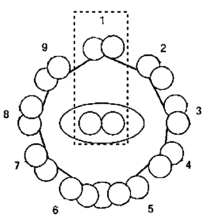
The following figure shows the so called "9+2" arrangement of the micritubules found in the flagellum which consists of a pair of cross-linked subfibers (named A and B) circumferentially surrounded by nine other pairs evenly spaced apart. Those arranged in a circle are connected by nexin bridges and each connects to the center via a radial link.
Radial link
k
Central sheath
Cross-bridges
Figure 3-2: This image shows the arrangement of the microtubuels and nexin bridges with in the flagellum.(Image reproduced from Mamalian Sperm Motility[3])
These structures are the main components used in the flagellum's movement when
driven by cellular dynein motors. The examined flagella of interest was one in which these motors were deactivated; consequently, its movements were simply passive re-actions to an applied force allowing for analysis of the structure itself.
This study chose to focus only on modeling a section of the flagellum as shown below in the diagram. This is valid because the interlayer slip occurs only between the center axenomes and any of the outer radially arranged axenomes; therefore, the control volume depicted below captures all of the physical phenomena under analysis.
I I
KTTh~
8
3
7
6
5
Figure 3-3: All of the physics in question can be answered by analysing only the portion included in the dashed box.
3.1.2 Interstitial Tissue and Elasticity
3.2
Interlayer Slip
Interlayer slip is present in many systems, especially those containing composite
ma-terials and is guided by a few general guidelines. First, the shear between layers is
continuous along the length of the structure. This means that local shears between layers have a large effect on the global deformation when the object under
considera-tion is long, particularly for 1 >> b. Second, the amount of slip allowed between the
layers is proportional to the transmitted load applied anywhere along the length of the body. Third, the strain distribution along the diameter (depth) of the structure is linear. Finally, at every section of the beam, each layer deflects the same amount without buckling.' Using this set of guidelines, a governing set of mechanical equa-tions can be derived and generalized. Additionally, it is important to note that one end of the layered structure must be fixed such that no displacement of one layer with respect to the other may occur. This requires that the contact length between the two layers be maintained throughout the structure's deformation[41.
3.2.1 Interlayer Slip in the Flagellum
As previously stated, the microtubules are important contributers to the motility of a flagellum. The mechanism through which these fiborous tubes manage to propel the organism consists of the same principles as the interlayer slip described above. The sliding friction between the doublets causes tension to form in different parts of the flagellum which then causes the structure to deform and bend in a motion that induces swimming. Each set of doublets can only slide headward in sperm causing it to move only in the headward direction. Furthermore, studies show that the velocity of the sperm is not affected by a change in viscocity, but the curvature and the surrounding flowfield of medium is greatly affected by such a change[3].
'Friction effects axe neglected and the bean is assumed to be homogenous throughout.
Chapter 4
Constructing the Model
4.1
Design Process
Model building began by determining what materials met the design criteria and had appropriate material properties given the important dimensionless parameters. Knowledge of the internal structure and the fuctional behavior of each part of the sperm guided the design descisions which led to the use of the components which emulated the desired values and behaviors.
4.1.1 Motivation for Design Decisions
The dimensionless parameter yt is the most important to match in the flagellum and is defined as y = L2(b2) where it is most sensitive to changes in length, L, and diameter, b, which are of the second order. Eb is the bending stiffness of the axenomes and K is the effective spring constant of the nexin bridges, given by K = nk L + C
where n is the number of springs on a side, k is the individual spring stiffness,1 and
C is some constant related to the rest of the internal structure and is the value which
must be sought out through deeper experimentation. Therefore, K must be varied to determine the optimal value of C; this gives a starting point for Kmin = 1.16 x 10⁴
where C = 0. For this configuration, the entirety of K must be provided by the
1In order for the representation to be symmetrical, and therefore valid, all of the springs must be of uniform stiffness.
springs.
Representative values of sperm properties were used to determine a value for t for which the model wiould be valid. These values are given in the table below and
lead to a value of p = 93.17.
EJ0.x14Nm2 K 2.0x10- N/m
b 185 nm
L 35 pm
Table 4.1: Data taken from sea urchin sperm to find a representative value of t.
For scaling purposes, the model must acheive a nearly identical p while being practical to build and analyze in experiments as well as emulate the dynamics of the flagellum; this provides further constraint as the diameter, b, must remain constant throughout the bending process and the supports for this constant diameter must be capable of keeping the plates separate without making the model rigid. Futher constraints were given by geometic properties; for example, the aspect ratio, 189:1, makes it difficult to find a scale at which building the model would be both useful for observation and practical for experimentation. Due to the limitations of the experimental set up, a length of L = 30cm and a diameter of b = 1.59cm which could then be plugged into y to guide the material selection process. The width, W, was chosen to be 5 inches in order to limit deformation to the vertical plane and eliminate torsional distortion which could cause error in the data collection process.
4.1.2 Materials
Shimstock was selected to represent the axenomes as it was a readily available material
with desirable properties. This gave a starting point for the design constraints as it has a determined stiffness of Eb = El = 7.2Nm2. Springs with constant k = 675.98N/m
were selected as the starting place for testing variations in K with n = 5, K =
1160N/m 2. They could be switched out for values of k in the range of 96.6N/m <
k < 675.98N/m for n = 5.
4.2
Prototypes and Design Optimization
After the initial design was conceptualized, a mini model was made to determine whether or not the components would attach and behave as envisioned. The following figure shows this first rough prototype.
Figure 4-1: The first iteration; constructed to ensure compadibility of components and integrity of design.
From this mini model it was determined that the springs should in fact be com-pression springs instead of extension springs in order to cause the structure to want to force itself back into place, thus causing counterbend to be observed.
The second iteration of the design is shown below which was built full scale for complete analysis. It was determined that the delrin spacers used were too heavy to be supported by the shim stock which caused it to deform under it's own weight. Additionally, it became clear that the spacers needed to be grouped together to keep them in place and ensure uniform spaceing between the two plates.
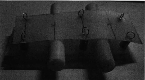
In the third iteration, the delrin rods were replaced by ABS tubes which signif-icantly decreased the weight and enabled the spacers to be woven together into a flexible raft-like structure as shown in the following figure.
Figure 4-2: Here the second iteration is shown where A is a top view of the model and B is a side view where the delrin spacers are clearly visible amongst the compression springs.
The string was woven to ensure each part had limited movement in the axial direction of the structure as well as free rotation about one another. The springs used had a spring constant of k = 675.98 which is the estimated upper limit. This model was capable of counter bend
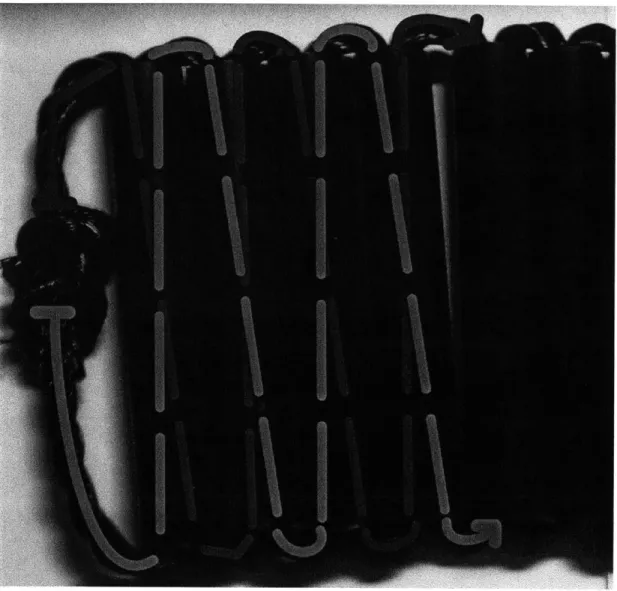
The final model simply replaced the chord used for weaving with a lighter string and the brace point was replaced by a square piece of ABS to allow for better clamp-ing. This final form is shown exhibiting counterbend below.
Figure 4-3: The tubes were strung together with a zig-zag pattern which looped around and constrained them to rotating about one another.
Figure 4-5: This iteration exhibited counterbend, but was still slightly overweight and the bracepoint was round which hindered clamping.
Figure 4-6: This final model exhibited the desired behavior and met design specifica-tions.
Chapter 5
Beam Curvature Under Forced
Conditions
5.1
Purpose of the Experiments
The experiments were performed to allow for verification of the model as an accurate representation of the flagellum. The data collected was used to ensure that more indepth analysis would be the next logical step for testing over a redesign of the model for more accurate representation.
5.2
Experimental Setup
The figure below depicts the laboratory set up for recording images under an induced load.
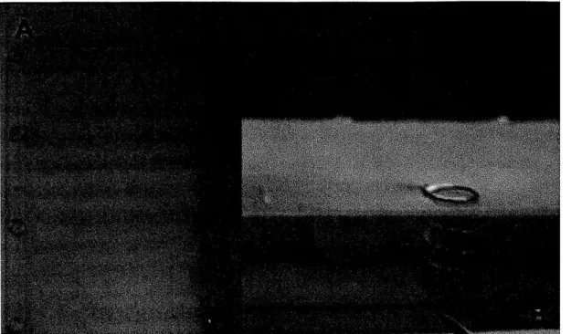
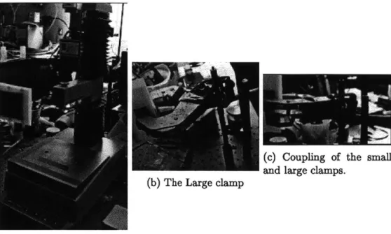
The beam was fixed in a horizontal position so that gravity will not affect data collection. The model was clamped at the base such that the ends were fixed in place setting a boundary condition where no displacement occurred along the length of the model and interlayer slip caused the diameter of the model to remain constant, even under loading conditions by allowing displacement of the free ends relative to one another as depicted in the image below.
con-(b) The Large clamp
(c) Coupling of the small and large clamps.
(a) The texture analyzer.
Figure 5-1: A large clamp was used in conjunction with the test tube clamp to allow for a stronger grip on the model which provided better support, and fixed the ends relative to one another as desired. The clamps were coupled inorder to maximize grip strength and allow for elevation from the testing surface via the stand.
IS
bb
0
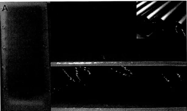
bFigure 5-2: Here it can be seen that the spring is extended at an angle after having started out with the two end points vertically aligned, indicating uneven extension of the end points of the beam[21.
stant diameter, is partially responsible for the counterbend. 30
5.3
Data Collection and Proceedure
After the beam was clamped in place a force was manually applied to the model and images of the curvature were taken with a grid block in the background to allow for graphical analysis of the achieved curvature; the grid was used for scaling purposes where the area of each square is 0.25cm2
Chapter 6
Conclusions
6.1
Validity of the Model
It was found that the construction was indeed valid for modeling the counterbend; however, the i value was not in agreement with the desired scaling value. This error can be attributed to variation in the Eb from the calculated value, as well as error in
K. However, the exact value of K can only be found via experimentation and variation
of the parameters on which K depends.
6.2
Recomended Future Study
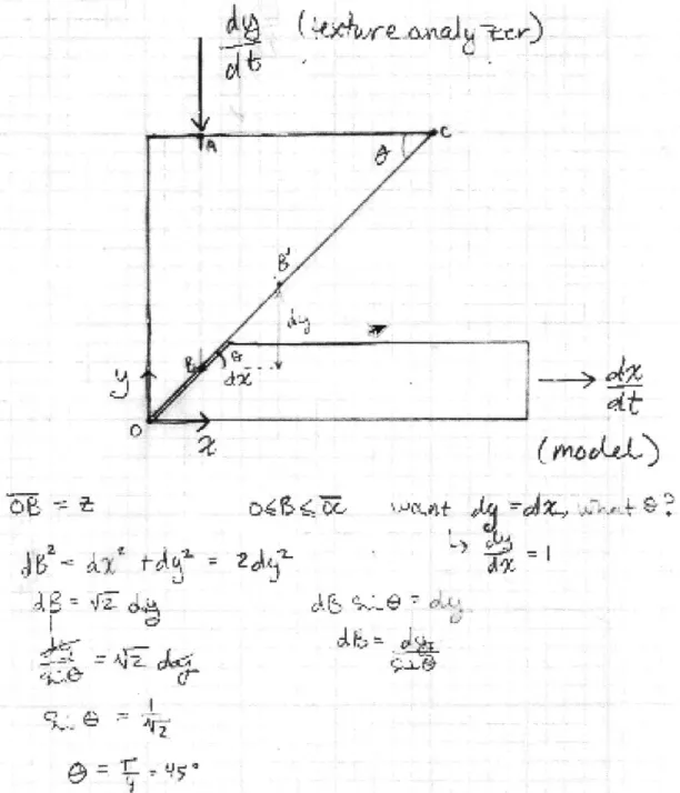
It is reccomended that for testing in a horizontal position a transformational mecha-nism be constructed to turn the vertical motion of the texture analyzer into horizontal forcing of the model. A simple proposed design is included in the figure below along with a proof defining the critical angle which will give the desired input/output rela-tionship. This angle was unsurprisingly found to be 45.
vk
W77tt
0"
Figure 6-1: A wedge mechanizm with a angled hypotenuse with a slope of 1 is rec-ommended for transforming orthogonally.
34 IJ~i j 0
,jr> ~
0'6.2.1 Beam Curvature and Displacement Under Forced Con-ditions
In order to observe the interactions responsible for the counterbend phenomena, the model should set up with appropriate boundary conditions on a texture analyzer. The texture analyzer can then be used to apply a known force to the model and record its displacement. Additionally, images should taken during deformation for further analysis of the curvature achieved by the model.
Variation of the variable K will allow for determination of the optimal value which should be used to accurately represent the properties of the sperm. This can be achived by varying the spring stiffness, the spacing of the springs, and the number of springs used.
The data can be used to calculate the effective bending stiffness of the model which allowed for prediction of the corresponding value in the flagellum via the dimensionless
Bibliography
[11 White, F.M. Fluid Mechanics. 6th Ed., New York: McGrawHill, 2008. 287-327. Print.
[21 Gadelha, H. Counterbend Notes Unpublished. 2-4. PDF.
[31 Gaffney, E.A.; Gadelha, H.; Smith, D.J.; Blake, J.R.; Kirkman-Brown, J.C. "Ma-malian Sperm Motility: Theory and Observation" Annual Review of Fluid
Me-chanics. (2011): 504-507. Print.
[41 Goodman, J.R.; ASCE, M.; Popov, E.P.; ASCE, F. "Layered Beam Systems with Interlayer Slip" Journal of the Structural Division: Proceedings of the American

![Figure 3-2: This image shows the arrangement of the microtubuels and nexin bridges with in the flagellum.(Image reproduced from Mamalian Sperm Motility[3])](https://thumb-eu.123doks.com/thumbv2/123doknet/14505989.528818/20.918.229.729.584.896/figure-arrangement-microtubuels-bridges-flagellum-reproduced-mamalian-motility.webp)