Publisher’s version / Version de l'éditeur:
Review of Scientific Instruments, 28, 12, pp. 1033-1037, 1958-02-01
READ THESE TERMS AND CONDITIONS CAREFULLY BEFORE USING THIS WEBSITE. https://nrc-publications.canada.ca/eng/copyright
Vous avez des questions? Nous pouvons vous aider. Pour communiquer directement avec un auteur, consultez la
première page de la revue dans laquelle son article a été publié afin de trouver ses coordonnées. Si vous n’arrivez pas à les repérer, communiquez avec nous à [email protected].
Questions? Contact the NRC Publications Archive team at
[email protected]. If you wish to email the authors directly, please see the first page of the publication for their contact information.
NRC Publications Archive
Archives des publications du CNRC
This publication could be one of several versions: author’s original, accepted manuscript or the publisher’s version. / La version de cette publication peut être l’une des suivantes : la version prépublication de l’auteur, la version acceptée du manuscrit ou la version de l’éditeur.
Access and use of this website and the material on it are subject to the Terms and Conditions set forth at
Deviations from one-dimensional heat flow in guarded hot- plate
measurements
Woodside, W.
https://publications-cnrc.canada.ca/fra/droits
L’accès à ce site Web et l’utilisation de son contenu sont assujettis aux conditions présentées dans le site LISEZ CES CONDITIONS ATTENTIVEMENT AVANT D’UTILISER CE SITE WEB.
NRC Publications Record / Notice d'Archives des publications de CNRC:
https://nrc-publications.canada.ca/eng/view/object/?id=9443872e-638f-4609-b314-9e93a8b44a44 https://publications-cnrc.canada.ca/fra/voir/objet/?id=9443872e-638f-4609-b314-9e93a8b44a44
Ser
TH1
N2lr2 no. 50 c . 2BLDG
C A N A D ADIVISION
O F BUlLDlNG RESEARCH
B U I L D I N G RESEARCH
(-xi-z-"
DEVIATIONS FROM ONE
-
DIMENSIONAL HEAT FLOW IN
GUARDED HOT- PLATE MEASUREMENTS
BY
WILLIAM WOODSIDE
R E P R I N T FROM T H E REVIEW O F S C I E N T I F I C INSTRUMENTS VOL. 2 8 . N O . 12, DECEMBER 1 9 5 7 , P . 1 0 3 3
-
1 0 3 7RESEARCH PAPER N O . 5 0
OF T H E
DIVISION O F BUILDING RESEARCH
OTTAWA
FEBRUARY 1958
This p u b l i c a t i o n
i s
b e i n g d i s t r i b u t e d by t h e D i v i s i o n o f B u i l d i n g Research of t h e N a t i o n a l Research Councilas
a c o n t r i b u t i o n towards b e t t e r b u i l d i n g i n Canada.I t
should n o t be reproduced i n whole o ri n
p a r t , w i t h o u t p e r m i s s i o n of t h e o r i - g i n a l p u b l i s h e r . The D i v i s i o n would be g l a d t o be of a s s i s t a n c e i n o b t a i n i n p s u c h permission. F u b l i c a t i o n s of t h e D i v i s i o n o f B u i l d i n g Research may be o b t a i n e d by m a i l i n g t h e a p p r o p r i a t e r e m i t t a n c e , (a Dank, W r e s s , o r P o s t O f f i c e Money Order o r a cheque made payable a t p a r i n Ottawa, t o t h e Receiver G e n e r a l of Canada, c r e d i t N a t i o n a l R e s e a r c h c o u n c i l ) t o t h e N a t i o r a l Research Council,Ottawa. Stamps a r e not a c c e p t a b l e .
A coupon s y s t e m has been i n t r o d u c e d t o make payments f o r p u b l i c a t i o n s r e l a t i v e l y simple.
Coupons a r e a v a i l a b l e i n denominations of
5 ,
25, and50
c e n t s , and may b e o b t a i n e d by making a r e - m i t t a n c e a s i n d i c a t e d above. These coupons may be used f o r t h e purchase of a l l N a t i o n a l Research C o u n c i l p u b l i c a t i o n s i n c l u d i n g s p e c i f i c a t i o n s ofReprinted from TEIE REVIEW OF SCIENTIFIC INSTRUMENTS, Val. 28: No. 12, 103S1037, December, 1957 Printed in U. S. A.
Deviations from One-Dimensional Heat Flow in Guarded
Hot-Plate Measurements
WILLIAM WOODSIDE
National Research Council of Canada, Division of Building Research, Ottawa, Canada
(Received April 12, 1957; and in final form, September 19, 1957)
A theoretical analysis is made of the error in thermal conductivity, measured by the guarded hot-plate apparatus, resulting from a temperature difference, or unbalance, between the test area and guard ring. The solution is obtained by the application of two successive Schwarz transformations, the assumptions having been verified by relaxation calculations. An expression is derived for the error heat flow in the test specimens. The agreement between calculated and measured values of the error heat flow for three different hot plates for which experimental data are available is 5% or better. I t is therefore now possible to calculate the maximum tolerable unbalance to achieve any desired accuracy in thermal conductivity measured by the guarded hot plate.
T
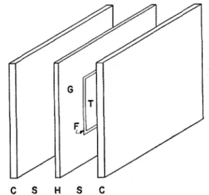
HE standard apparatus for the determination of conductivity is calculated is derived assuming that one- the thermal conductivity of building and in- dimensional normal heat flow occurs between the test sulating materials is the guarded hot plate? The essen- area and cold plates.tial parts of the apparatus are shown schematically in Unidirectional heat flow does not occur in the test Fig. 1. Two identical test specimens of known thickness region when (i) heat losses or gains a t the edges of the are inserted between the plates and the assembly specimens are excessive and/or (ii) a temperature clamped together to ensure good thermal contact be- dserence exists between test area and guard ring. tween adjacent surfaces. Constant temperature liquid is Errors due to (i) have been discussed by Somers and circulated through each of the cold plates and regulated C y p h e r ~ , ~ D ~ s i n b e r r e , ~ and W ~ o d s i d e . ~
current passed through the heaters of the test area and To eliminate errors due to temperature differences guard ring of the hot plate, so that a temperature between the test area and guard ring, the guard ring gradient is set up across each specimen. When a steady- must be maintained a t the same temperature as the state temperature equilibrium has been established, the test area so that no net heat exchange occurs between thermal conductivity of the test specimens may be the two. This is done by varying, either manually or calculated from the power input to the test area, the automatically, the magnitude of the guard ring heating area of the test area, the temperature difference between current until the differential thermocouples connected the hot and cold sufraces of the specimens, and the across the gap separating test and guard areas register thickness of the specimens. The formula by which the zero emf. When this is the case, the hot plate is said to be balanced. In practice, however, perfect balance is seldom achieved throughout the entire equilibrium period of a test. It is therefore important to be able to estimate the magnitude of the error in measured con- ductivity caused by small differences in temperature between the guard ring and test area.
Figure 2 represents a cross section of the apparatus through the center of the test area. Suppose the tem- peratures are as shown in the figure, the guard ring being 1 O F cooler than the test area (1 O F unbalance). A
greater heat input to the test area will be required under these conditions than if the test and guard areas had
//
uAv"
both been a t the same temperature of 96OF. If Qrepresents the rate of heat input to the test area under balanced conditions, and (Q+q) the rate of heat input under the conditions shown in Fig. 2, then the relative
C S H S C error Ak/k equal to q/Q. The error heat flow rate for a in the measured thermal conductivity is 1°F un-
FIG. 1. Guarded hot plate apparatus. C, C-cold plates; S, S- balance will be called q. It is composed of two parts positions of test specimens; H-hot plate; G-guard ring; T-test
area; F--gap. E. V. Somersand J. A. C ~ p h e r s , Rev. Sci. Instr. 22,583 (1951). a G. M. Dusinberre, Rev. Sci. Instr. 23, 649 (1952).
'American Society for Testing Materials, Designation C 177-45, 4 W. Woodside, "Analysis of Errors due to Edge Heat Loss in "Standard Method of Test for Thermal,,Conductivity of Materials Guarded Hot Plates," Presented at ASTM Symposium on by Means of the Guarded Hot Plate, ASTM Standards, 1955, Thermal Conductivity Measurements, Philadelphia, Febraury 6,
Part 3, pp. 1084-1092. 1957 (to be published).
1033 N.R.C. 4560
G
1034 W I L L I A M W O O D S I D E
COLD PLATE 55'F
////////'///'////////
!
The analysis is based on assumptions that have been verified by relaxation calculations. The values of c predicted by the analysis are compared with the experimental values obtained for the three hot plates tested previously?
ANALYSIS
Application of the Schwarz Transformation For the purpose of evaluating the error heat flow and lateral heat flow in the test specimens due to a l ° F un- balance, the cross section shown in Fig. 2 may be reduced to that shown in Fig. 3. This is permissible for the following reasons: (i) since only the error and lateral heat flows in the specimens are of concern here (the heat flow qo directly across the gap may be evalu- ated independently) the heater plate of finite thickness may be replaced by a mathematical line; (ii) since only temperature differences are needed in heat conduction calculations, the temperatures shown in Fig. 2 may all be reduced by any equal amount, in this case 55°F. Also since the system is symmetrical about the two dotted lines shown, only the top left-hand comer of Fig. 3 need be considered.
The problem of evaluating the lateral heat flow across the dashed lines in Fig. 3 and the error heat flow out of the test area is still not amenable to mathematical solution.
i
COLD PLATE 55* FFIG. 2. Cross section of guarded hot-plate apparatus and test specimens through center of test area (not to scale). (a) the heat transfer directly across the gap separating test area and guard ring q o and (b) the error heat flow rate in the test specimens ql
The heat flow between the test section of plate and specimens and the guard section of plate and specimens when there is an unbalance (i.e., heat flow across the dotted lines in Fig. 2) is the lateral heat flow rate q', and this also is composed of two parts (a) the heat transfer directly across the gap qo and (b) the lateral heat flow in the specimens qlt,
Q'= -
QOSQI'.
- aThe lateral heat flow q' is not the same as the error heat flow q. However it is the error heat flow q that deter- mines the error in measured conductivity. ,
I n a previous paper6 which described experimental investigations of unbalance errors with three different hot plates, it was shown that
The following assumptions are made. (a) The distor- tion in the isotherms and heat flow lines near the gap due to the unbalance does not extend to the edges of the specimen or to the center of the test area. This is a
reasonable assumption since the ratio of temperature unbalance to hot-plate-cold-plate temperature differ- ence (in the above case 1/41) is usually small, and the , .
gap width is usually small compared-with the linear dimension of the test area. This assum~tion was where qo and c are the unbalance sensitivity constants
for any given hot plate. Values of qo and c were obtained for the three hot plates tested.
verified by a relaxation calculation of the temperature distribution in the test specimens for two designs of heater plate (Plates A and B of reference 5). Thus the specimens and plates may be considered to extend to infinity on each side of the gap for the purposes of lateral If the values of qo and c for a given hot plate are
known, it is possible to calculate beforehand the
maximum tolerable unbalance in anv test which will or error heat %ow calculation.
(b) The temperature distribution in the test speci- keep the error in measured conductivity below any
desired limiting value. Thus qo and c are important constants for any hot plate. Tt was shown in6 how these constants may be determined experimentally and also how the value of qo may be calculated. However in the
I
COLD PLATE
i
8 . 0I I I I
~ S Y M M E T ~ R Y A X E s $ + I
-. GUARD 8%:: TEST AREA 8 ~ 4 1 I GUARD dl B.40 .
design of guarded hot plate apparatus it would be useful to be able to calculate the values of both constants for any particular heater plate before construction of the plate. This present paper is concerned with the ana- lytical evaluation of the error heat flow in the test
specimens q ~ = c . k (and hence of the constant c) and I I ! I I
COLD PLATE
i
8 = 0also of the lateral heat flow in the specimens ql'.
W. Woodside and A. G. Wilson, "Unbalance Errors in Guarded Hot Plate Measurements," Presented a t ASTM Symposium on Thermal Conductivity Measurements, Philadelphia, February 6,
1957 (to be published).
FIG. 3. Cross section of apparatus and test specimens, with hot and cold plates replaced by isotherms.
and therefore along the gap, aO/ay=O.
Y
G U A R D E D H O T - P L A T E M E A S U R E M E N T S 1035 mens is the same as that which would be obtained v
considering only two-dimensional heat flow. The error involved in this assumption has also been shown to be very small by relaxation calculations. Thus the system may be handled by the application of a two-dimensional conformal transformation. Also since the differential equation for heat conduction is linear, the lateral and
error heat flows in the specimens, under the temperature u conditions shown in Fig. 3, are the same as under the
0.1
GUARD RING GAP TEST AREA
following temperature conditions : test area temperature
e=o
FIG. 4. Simplified plate-specimen heat flow system showing reduced temperature boundary conditions.
- -
w =
The determination of the lateral heat flow across the dashed line bisecting the gap, or of the heat flow out of the test area CB, is not simple in the system shown. Figure 4 will therefore be transformed to a simpler system in which the solution is obvious, by means of two successive Schwarz-Christoffel transformations. Figure 4 will be taken to represent the system in the complex z= (x+iy) plane, and, as a first step, will be
transformed into the w= (u+iv) plane shown in Fig. 5. The space inside the parallel lines in Fig. 4 is trans- formed to the space above the u axis in Fig. 5 with the points A to G in correspondence, by the following Schwarz transformation :
dz/dw = b/ (w+ a). Integrating,
z= b[ln(w+a)+ b'],
8= 1, guard ring temperature 8=0, cold plate tempera-
Setting w=
-
1 when z= -24 thena-l= 1
-
e-2rdlh 0 )av a
Thus the equation transforming Fig. 5 t o Fig. 4 is
z= h[(w/a)+ll. (2)
8.1
Figure 5 will now be transformed to the t= (r+is) plane shown in Fig. 6, by a second Schwarz transformation :
dt/dw= bl[w(w+ I)]-+. Integrating,
t= ibl ~in-~(2w+l)+bl',
- , - -.-
ture 8=0. The system has therefore been simplified to FIG. 5. Representation of Fig. 4 after application that shown in Fig. 4. of first transformation.
Choose C to be the origin of an x-y Cartesian co- ordinate system. Let the gap width be 2d, the linear and
dimension of the test area 2 (l+d) (so that B represents z= b ln[(w/a)+
11.
the center of the test area) and the thickness of thespecimen h. The temperature boundary conditions are Along FG, w is real and less than -a, and the imaginary as shown in the figure. The boundary condition a t the part of z is ih,
gap requires zero heat flow normal to the gap width,
:.
b= h/a.where b1 and blt are constants. When t=O, w=O;
:.
blt=-iiabl. When t=-a, w=-1;:.
bl=-i. Equation (3) therefore transforms Fig. 5 into Fig. 6. The single transformation which transforms Fig. 4, thewhere b and bt are constants yet to be determined.
% = O When z=0, w=0, since C is the origin in both planes.
FIG. 6. Representation of Fig. 4 after application
1036 W I L L I A M W O O D S I D E
original system, directly into Fig. 6, is obtained by eliminating w from Eqs. (2) and (3). This results in
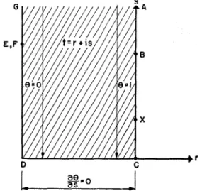
The solution of the problem in the t= (r+is) plane of Fig. 6 is straightforward since ABC is at temperature
O= 1, DEFG a t temperature O=0, there is no heat flow across CD, (i.e., aO/ds= 0) and A and G are at s=
+
a.The isotherms are therefore given by r=constant and the heat flow lines by s=constant, and the temperature distribution is given by
Evaluation of the Lateral H e a t Flow As a first solution, the lateral heat flow crossing the line 00' in Fig. 4 will be determined. The line 00' bisects the gap between test area and guard sections of the speci- men. I n Fig. 6 the point corresponding to 0' in Fig. 4 is somewhere on DC, the exact location being unim- portant, since in Fig. 6, the heat flow is one-dimensional, However the ordinate (value of s) for point 0 in the t plane must be determined.
At 0 in the z plane, z= (-d+ih). Substituting this into Eq. (4),
cost=
-
2 ~ ( e - ~ ~ l ~ + 1)+ 1.But cost=cos(r+is) and since r = -a for point 0, cost= - C O S ~ S . Therefore, a t 0,
Therefore the heat flow across the line OO', for unit depth perpendicular to the plane of the figure, is equal to
so 1 k
.- .-,
144 .nr
region of the test specimen adjacent to the gap, and the heat flow crossing 00' was evaluated neglecting the fact that the heater plate test area is square, and therefore the heat flow crossing from test section to guard section of the specimen is three-dimensional. T h e following solution for the error heat flow retains the assumption that the two-dimensional temperature distribution is close enough to the actual distribution as to have negli- gible effect on the heat flow out of the test area, but the heat flow out of the test area will be calculated taking account of the three-dimensional nature of the flow.
I n the z plane (Fig. 4) point B corresponds to the center of the test area. Consider a voint X distant x
from C on the line BC. The point corresponding to X in the t-plane will be determined. Since X is on BC, the valueif r a t X is zero. From Eq. (4) the value of s at X is given by
~ , = c o s h - ~ ( 2 a ( e ~ ~ l ~ - 1)+1).
For the heat flow out of XC, for unit depth perpen- dicular to the plane of Fig. 6, in the t plane, one obtains
But the heat flow out of XC, for unit depth perpen- dicular to the plane of Fig. 4, in the z plane is
Equating these two expressions for the heat flow out of XC, and differentiating both sides with respect to x,
Therefore the total heat flow out of the test area, taking account of the three-dimensional nature of the flow, and assuming that the isotherms are concentric squares centered on B, is
Hence for a heater plate with a test area, perimeter of
8(l+d), the lateral heat flow in both specimens for a Q+ (q-qa)=-- 2k
J'
8(1-%)(:)
d ~ . 1°F unbalance, neglecting corner effects, is given by 144 POSubstituting for so,
Expanding, and then integrating by parts, this becomes k 1
Q+ (q- qo) =-
1
c o ~ h - ~ ( 2 a ( e ~ ~ l " - 1)+
1)dx. 9aLet this integral be denoted by I , since it can only be evaluated numerically, then
.
,,Q+ (q- 90) = k I / 9 ~ . Btu/hr OF unbalance. (6)
But 0. the total heat flow from both surfaces of the L ,
Evaluation of the Error H e a t Flow test area, under balanced conditions when both test area and guard ring are a t temperature B= 1, is given by The above solution for the lateral heat flow assumed
G U A R D E D H O T - P L A T E M E A S U R E M E N T S 1037 Therefore the error heat flow in the specimens (q-qo)
for a 1°F unbalance is
TABLE 11. Cornparsion of calculated and experimental results.
Dimensions of hot plate Error or lateral heat flow in specimens and specimens (in.) (Bto/hr O F unbalance)
Side of Speci- Calcu- Calcn- Calcu-
Size of test G a p men lated lated lated Measured hot area width thick- equation equation equation error heat plate 2 ( l + d ) 2 d ness h ( 6 ) (83 ( 7 ) flow Therefore
c= (q- qo)/k= 1/9r- (l+d)?/18h
1
where
I
and the approximate error heat flow, respectively, in the test specimens, for heater plates A , B, and C of (5) for which experimental values of the error heat flow in the specimens are available. The comparison between calculated and experimental values is shown in Table 11. In all cases the lateral heat flow is larger than the error flow. The agreement between the calculated and experimental values of the error heat flow is satisfactory, being 5% or better. The approximate error heat flow calculated from the simpler equation (8) diEers by not more than 8% from the accurate error heat flow [Eq. (7)] and therefore should be suitable for design calculations.
and
I
The evaluation of the integral I defined in Eq. (7) requires the plotting of the function
and the determination of the area under this curve between the limits x= 0 and x= 1, by Simpson's rule or the use of planimeter. An approximate value of I which is more easily evaluated is given by
NOMENCLATURE
Q=rate of heat input to test area,
q= total error heat flow for a 1°F unbalance, Btu/hr
O F unbalance,
and hence the approximate value of c corresponding to this value of I is
k= thermal conductivity of test specimens, Btu in./hr sq ft OF,
Ak=error in thermal conductivity due to 1°F un- balance, Btu in./hr sq ft OF,
qo=heat transfer directly across gap, Btu/hr O F
unbalance,
ql=error heat flow rate in test specimen, Btu/hr OF where a has the same value as before.
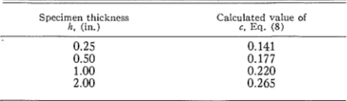
The parameter c is not strictly a constant for a given hot plate, its value depending upon the thickness of the
specimens being tested. Table I shows values of c unbalance,
ql= total lateral heat flow, Btu/hr OF unbalance, qll= lateral heat flow rate in test specimens, Btu/hr OF TABLE I. Effect of specimen thickness upon the error heat flow for
hot plate with 2(1+d)=4, and 2d=0.0625 in.
Specimen thickness Calculated value of
h. (in.) c. Eq. (8)
unbalance, O= temperature,
c=slope of q vs k graph,
h= thickness of test specimen, in.,
2d= width of gap separating test area and guard ring, in.,
21= linear dimension of test area plate, in. calculated from the approximate Eq. (8) for different ACKNOWLEDGMENTS
specimen thicknesses for a hot plate having 2 1 = 3 g in. ~h~ author wishes to thank D ~ . D. G. stephenson for and 2d=& in. (the dimensions of the 8-in. National the relaxation solutions and for many helpful discus- Bureau of Standards design). sions, and also Mr. A. G. Wilson and Dr. N. B. Hutcheon for assistance in preparing the paper. This paper is a
RESULTS
contribution from the Division of Building Research, Equations (6), (7), and (8) are now applied to the National Research Council of Canada and :s published calculation of the lateral heat flow, the error heat flow, with the approval of the Director of the Division.
A