HAL Id: hal-02066073
https://hal.laas.fr/hal-02066073
Submitted on 13 Mar 2019
HAL is a multi-disciplinary open access
archive for the deposit and dissemination of
sci-entific research documents, whether they are
pub-lished or not. The documents may come from
teaching and research institutions in France or
abroad, or from public or private research centers.
L’archive ouverte pluridisciplinaire HAL, est
destinée au dépôt et à la diffusion de documents
scientifiques de niveau recherche, publiés ou non,
émanant des établissements d’enseignement et de
recherche français ou étrangers, des laboratoires
publics ou privés.
Compact C-band Rectenna for Satellite Applications
Alexandru Takacs, Abderrahim Okba, Hervé Aubert
To cite this version:
Alexandru Takacs, Abderrahim Okba, Hervé Aubert. Compact C-band Rectenna for Satellite
Ap-plications. IEEE Wireless Power Transfer Conference (WPTC), Jun 2018, Montréal, Canada.
�hal-02066073�
Compact C-band Rectenna for Satellite Applications
Alexandru Takacs
1, Abderrahim Okba
1and Hervé Aubert
11LAAS-CNRS, UPS, INPT, Toulouse, France
Email: [email protected], [email protected], [email protected]
Abstract—This paper addresses the design and the
characteri-zation of a compact C-band rectenna for satellite applications. The proposed flat dipole rectenna achieves an efficiency of 58.2% at 3.25 GHz when illuminated with an electromagnetic power density of only 33.9 µW/cm2. The proposed rectenna is also
com-pact; its size is 1334 mm2 that is only 16% of the square
wave-length at 3.25 GHz.
Index Terms— RF and microwave energy harvesting,
recten-na, wireless power transmission
I. INTRODUCTION
The high gain microwave antennas, mounted on the external panels of the geostationary telecommunication satellite, are fed by high RF & microwave power (in the range of 100 W). The electric field generated by the spill-over loss of these microwave antennas can reach the following highest levels (effective values): 40 V/m in C-band, 49.5 V/m in X-band, 106 V/m in Ku-band, and 127 V/m in K-band [1]. Conse-quently, an important amount of electromagnetic energy is available around the satellite and illuminates the antenna pan-els. The harvesting of the electromagnetic energy generated by the microwave antennas was identified as an interesting solu-tion to power autonomous wireless sensors. These autono-mous wireless sensors can be deployed along the surface of the panels for structure health monitoring [1]. This paper pre-sents recent results obtained in C-band using an innovative rectenna. The proposed rectenna is composed of a flat dipole antenna enclosed by a rectangular ring and a single diode rectifier. The topology and the design methodology are de-tailed in Section II while the experimental results are present-ed in Section III.
II. PROPOSED RECTENNA:TOPOLOGY AND DESIGN
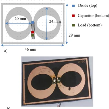
The topology of the proposed rectenna is presented in Fig. 1. It consists of a broadband flat dipole antenna (enclosed by a rectangular ring) integrated with a rectifier using a Schottky diode mounted in shunt configuration. The rectangular ring was properly dimensioned in order to lower the reso-nant/operating frequency of the flat antenna. Due to the use of the outer rectangular ring the size of the flat dipole anten-na/rectenna is only of 46 mm x 29 mm. The rectifier is com-posed of a HSMS2850 Schottky diode from Avago, a shunt capacitor (100pF) and a resistive load. The diode is mounted on the top of the rectenna (as illustrated in Fig. 1) while the shunt capacitor and load are connected on the back-side of the
rectenna. Two metallic via-holes are used in order to connect the diode (mounted on the top of the PCB) with the shunt capacitor (located of the bottom of the PCB). The position of the shunt capacitor is critical and impacts the impedance matching between the antenna and the rectifier. Simulations and experiments (not shown here) were performed and the optimal distance (between the shunt capacitor and the diode) is 1.3 cm. Elliptical holes, properly dimensioned (outer radius: 7.5 mm, inner radius: 6 mm) are inserted on the flat dipole in order to reject the high order harmonics generated by the recti-fier.
Fig. 1. Flat Dipole Rectenna (FDR): (a) the layout and the main dimen-sions and (b) photo of the manufactured rectenna.
The Flat Dipole Rectenna (FDR) was designed to operate at 3.4 GHz. At this frequency the satellite antenna panel is illu-minated (due to the spill-over losses of the C-band broadcast-ing antenna) by an electric field: 2 V/m < E-field < 15 V/m (1 µW/ cm2 < electromagnetic power density < 59.7 µW/cm2)
[2].
III. SIMULATION AND EXPERIMENTAL RESULTS
The Flat Dipole Antenna (FDA) was designed from inten-sive electromagnetic simulations (method of moments, Altair
Diode (top) Capacitor (bottom) Load (bottom) a) b) 29 mm 46 mm 20 mm 24 mm
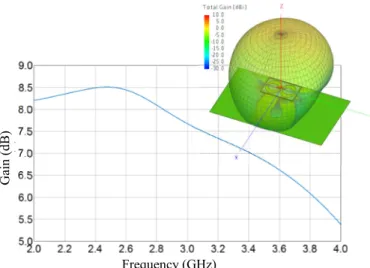
FEKO). The highest gain of the FDA is of 2 dBi and can be increased when a metallic reflector is properly positioned behind the antenna. The simulated gain (along the z-axis) of the FDA with the reflector (size: 157 mm x 92 mm) positioned at 27 mm behind the antenna is displayed in Fig. 2 as a func-tion of the frequency. The simulated input impedance is shown in Fig. 3. In order to maximize the performances of the FDR a complex conjugate impedance matching technique (between the rectifier and the FDA) was adopted. The input impedance of the rectifier was initially estimated by using a close-form expression [3]-[4]. At this stage, the impact of the vias-holes, coplanar stripline (on the bottom side) and the mounting position of the RF shunt capacitor are neglected. The position of the shunt capacitor was tuned in order to max-imize the FDR performances.
Fig. 2. Simulated (FEKO) maximum gain of FDA as a function of the frequency. The inset shows the 3D (gain) radiation pattern at 3.4 GHz.
Fig. 3. Simulated (FEKO) input impedance of FDA as a function of the frequency (continuous blue curve: real part; dotted green curve: imaginary part).
The experimental setup positioned in an anechoic chamber (to prevent any interferences or undesirable multipath effects) shown in Fig. 4 was used to characterize the rectenna. A mi-crowave signal generated from the Anritsu MG3694B genera-tor is injected at the input of a transmitting (Tx) horn antenna through a coaxial cable. The horn antenna illuminates the
rectenna under test, positioned in the far-field region of the Tx antenna, with a linearly-polarized E-field. An automatic ac-quisition routine is implemented in Labview software from National Instruments to speed-up the acquisition process. The harvested DC voltage is then measured by using a DC multi-meter. The DC power can be derived from the measured DC voltage, as long as the load is known. The RF-to-DC conver-sion efficiency η (in %) of the rectenna can be computed by using the following expression [5]:
𝜂 =𝑃𝑃𝐷𝐷 𝑅𝑅∙ 100 = 𝑃𝐷𝐷 𝑆 ∙ 𝐴𝑒𝑒𝑒∙ 100 = 4 ∙ 𝜋 ∙ 𝑃𝐷𝐷 𝑆 ∙ 𝐺𝑅∙ 𝜆² ∙ 100 (1)
where 𝑃𝐷𝐷is the harvested DC power, 𝑆 is the incident
elec-tromagnetic power density, 𝐴𝑒𝑒𝑒 is the antenna effective area,
𝐺𝑅 is the gain of the (rectenna’s) antenna and 𝜆 is the
free-space wavelength of the illuminating electromagnetic wave at the operating frequency. The electromagnetic power density S can be computed as a function of the E-field effective value 𝐸 (V/m) on the antenna surface. This value is derived from mi-crowave power Pt injected to the input port of the transmitting
horn antenna (gain 𝐺𝑡) positioned at a distance 𝑑 from the
rectenna, as follows: 𝑆 = 𝐸2
120 ∙ 𝜋 =
30 ∙ 𝑃𝑡∙ 𝐺𝑡
𝑑2∙ 120 ∙ 𝜋 (2)
Fig. 4. Experimental setup used to characterize the manufactured recten-na.
A RF power density of 33.9 µW/cm2 (that roughly
corre-sponds to the average RF power density generated by the spill-over losses of the C-band broadcasting antenna at 3.4 GHz) was generated by adopting the following configuration: Pt=27
dBm (the coaxial cable and connector insertion losses of 1dB was removed from Pt), 𝐺𝑡=11.87 dBi and 𝑑=1.20 m.
The following approach was adopted in order to character-ize our rectenna: (i) a frequency sweep was conducted for a selected load (1.5 kΩ) in order to find the optimal operating
Frequency (GHz) G ai n (d B) Frequency (GHz) Inp ut im pe da nc e (Ω ) Tx horn antenna RF power generator DC multimeter Rectenna
frequency (at this frequency the harvested DC power and the efficiency are maximized on the given load); (ii) the optimal load and then the maximum harvested DC power and the maximum efficiency were determined at this optimal operat-ing frequency. The measurements were performed without and with a metallic plate, positioned at 2.7 cm behind of the rectenna. This metallic plate simulates the presence of the metallic part of the satellite antenna panels. The obtained results (measured DC voltage and DC power), as a function of the frequency, are depicted in Fig. 5 and Fig. 6, respectively.
Fig.5. Measured DC voltage (mV) for the FDR (incident power density: S=33.9 µW/cm2, load 1.5 kΩ) as function of the frequency: dotted blue curve
(without any reflector plane), continuous red curve (with a metallic reflector positioned at 2.7 cm behind the rectenna)
Fig.6. Measured DC power (µW) for the FDR (incident power density: S=33.9 µW/cm2, load 1.5 kΩ) as function of the frequency: dotted blue curve
(without any reflector plane), continuous red curve (with a metallic reflector positioned at 2.7 cm behind the rectenna)
As shown in Fig. 6, a maximum DC power of 475 µW was obtained at 3.25 GHz with a load of 1.5 kΩ when the reflector is positioned at 2.7 cm behind the rectenna. Due to the adopt-ed antenna topology and matching technique, FDR exhibits also a wideband behavior: the half (DC-harvested) power frequency bandwidth is approximately of 20% (0.65 GHz). The optimal operating frequency is of 3.25 GHz instead of the targeted 3.4 GHz (that is a frequency shift of 4.5%), and it may be mainly caused by: (i) the approximation made when using the close-form expression for estimating the input im-pedance of the rectifier, and (ii) the technological inaccuracies when manufacturing and the assembling the FDR. This
fre-quency shift (of the maximum efficiency operating point) of 4.5% is not so critical because the half (DC harvested) power frequency bandwidth is 20%.
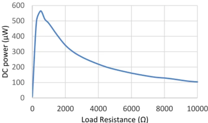
Fig.7. Measured harvested DC power as function of the load resistance for the FDR with a reflector positioned at 2.7 cm behind the rectenna (incident power density: S=33.9 µW/cm2, frequency: f=3.25 GHz)
The optimal purely resistive load and the maximum effi-ciency were experimentally determined for FDR at 3.25 GHz. As shown in Fig.7 and Fig.8, the optimal load is of 500Ω. For this load, the harvested DC power and efficiency are of 565 µW and 58.2%, respectively. We note that the efficiencies reported in Fig. 8 are undervalued as the simulated gain 𝐺𝑅
(=7.26 dBi, see Fig. 2) is adopted here for deriving the effi-ciencies.
Fig. 8 Efficiency (%) as function of the load resistance for the FDR with a reflector positioned at 2.7 cm behind the rectenna (incident power density: S=33.9 µW/cm2, frequency: f=3.25 GHz)
In Table I, the rectenna performances are compared with state-of-art designs operating at (almost) the same frequencies. The rectenna proposed in this paper was designed for energy harvesting applications (on board of broadcasting geostation-ary satellites) in C-band and operates efficiently for low value of the RF power densities.
0 100 200 300 400 500 2 2,5 3 3,5 4 DC p ow er ( µW ) Frequency (GHz) 0 100 200 300 400 500 600 0 2000 4000 6000 8000 10000 DC p ow er ( µW ) Load Resistance (Ω) 0 200 400 600 800 1000 2 2,5 3 3,5 4 DC v ol ta ge (m V) Frequency (GHz) 0 10 20 30 40 50 60 0 2000 4000 6000 8000 10000 Ef fici en cy (% ) Load Resistance (Ω)
Table I. Benchmark Results Refs. Operating frequency f0 (GHz) Power density (µW/cm²) or received RF power (dBm) Har-vested DC power (mW) Rectenna efficiency (%) Antenna Surface (λ0 is the wavelength at f0) [6] 2.45 525 µW/cm² 4.97 63 10 x 11 cm² (0.73*λ0²) [7] 2.45 13 dBm NR 72.5 13.5 x 9.3 cm² (0.83*λ0²) [8] 2.4 22 dBm 130 82.3 10 x 10 cm² (0.64*λ0²) [3] 5.8 8.77 mW/cm2 49.1 82.7 NR [9] 5.8 12 mW/cm² NR 76 NR This work 3.25 33.9 µW/cm 2 (-0.1 dBm) 0.57 58.2 4.6 x 2.9 cm² (0.16*λ0²) NR: Not Reported
In order to quantify the electromagnetic energy illuminating the rectenna and to compute the RF-to-DC conversion effi-ciency two approaches can be used. The electromagnetic en-ergy can be expressed in terms of power densities (this work, [3], [6], [9]) or alternatively in terms of the estimated RF power at the input of the rectifier [7]-[8]. We note that most of the published designs (see, e.g., [3][9]) covering (the upper) C-band were designed for wireless power transmission appli-cations at 5.8 GHz and optimized for very high levels of inci-dent RF powers (8.77 mW/cm2 or 12 mW/cm²). Compared
with the reported designs operating in the ISM 2.45 GHz band, our rectenna is significantly more compact and operates very efficiently when illuminated with much lower electro-magnetic power density (34 µW/cm2 for this work as
com-pared with 525 µW/cm² in [6]). The estimated RF power at the input of the rectifier is also significantly lower (-0.1 dBm for this work as compared with 13 dBm in [7] or 22 dBm in [8]).
IV. CONCLUSION
An innovative C-band rectenna using a compact flat dipole antenna was proposed. This rectenna operates very efficiently for low level of RF power densities. The maximum efficiency of 58.2% was obtained for the incident RF power density of 33.9 µW/cm2. The rectenna size is only 16% of the square
wavelength at 3.25 GHz.
ACKNOWLEDGMENT
The authors wish to acknowledge Gaël Loubet for his valu-able help during the rectenna characterization and French Space Agency (CNES) for partially supporting this research in the frame of several past R&T Grants.
REFERENCES
[1] A. Takacs, H. Aubert, S. Fredon, L. Despoisse, H. Blondeaux, “Micro-wave power harvesting for satellite health monitoring”, IEEE Trans.
Microw. Theory Techn., Vol.: 62, Issue: 4 , pp. 1090 - 1098, April 2014.
[2] Study of various micro-sources for energy generation and storage on
board satellites, Report for the French Space Agency, Grant n°
115052/201, 2011-2012 (in french)
[3] Y.-H. Suh and K. Chang, “A high-efficiency dual-frequency rectenna for 2.45- and 5.8-GHz wireless power transmission,” IEEE Trans.
Mi-crow. Theory Techn., vol. 50, no. 7, pp. 1784–1789, July 2002.
[4] J. Guo, X. Zhu, “An Improved Analytical Model for RF-DC Conver-sion Efficiency in Microwave Rectifiers”, IEEE MTT-S International
Conference, Montreal, QC, Canada, 17-22, June 2012.
[5] Z. Popovic; E.A. Falkenstein, D. Costinett, R. Zane, Low-Power Far-Field Wireless Powering for Wireless Sensors, Proceedings of the IEEE, Vol. 101, No. 6, pp.1397-1407, June 2013.
[6] Z, Harouni, L, Cirio, L, Osman, A, Gharsallah, and O, Picon, “A Dual Circularly Polarized 2,45-GHz Rectenna for Wireless Power Transmis-sion,” IEEE Antennas Wireless Propagat. Lett., Vol. 10, pp. 306–309, 2011
[7] N. Mei-Juan, “A compact 2.45 GHz Broadband Rectenna Using Grounded Coplanar Waveguide.” IEEE Antennas Wireless Propagat. Lett., vol. 14, pp. 986 – 989, January 2015.
[8] J. H. Chou, D. B. Lin, K. L. Weng, and H. J. Li, “All Polarization Receiving Rectenna With Harmonic Rejection Property for Wireless Power Transmission,” IEEE Trans. Antennas Propagat., vol. 62, no. 10, pp. 5242–5249, Oct. 2014.
[9] Y.-J. Ren and K. Chang, 5.8-GHz Circularly Polarized Dual-Diode Rectenna and Rectenna Array for Microwave Power Transmission,
IEEE Trans. Microw. Theory Techn., Vol.54, Issue 4, pp 1495-1502,
![Table I. Benchmark Results Refs. Operating frequency f 0 (GHz) Power density (µW/cm²) or received RF power (dBm) Har-vested power DC (mW) Rectenna efficiency (%) Antenna Surface (λ0 is the wavelength at f 0 ) [6] 2.45 525 µW/cm² 4.97 63](https://thumb-eu.123doks.com/thumbv2/123doknet/14263319.489527/5.918.53.456.96.370/benchmark-results-operating-frequency-received-rectenna-efficiency-wavelength.webp)
