Origin of the f
f
f
, 69
, 69
, 69
±±±peaks in YBa
2Cu
3O
72dfilms grown
on cubic zirconia substrates
D. G. SchlomDepartment of Materials Science and Engineering, The Pennsylvania State University, University Park, Pennsylvania 16802-5005
E. S. Hellman, E. H. Hartford, Jr., and C. B. Eoma)
AT&T Bell Laboratories, Murray Hill, New Jersey 07974-0636
J. C. Clark
Department of Materials Science and Engineering, The Pennsylvania State University, University Park, Pennsylvania 16802-5005
J. Mannhart
IBM Research Division, Zurich Research Laboratory, CH-8803 R¨uschlikon, Switzerland
(Received 26 September 1995; accepted 3 January 1996)
The c-axis oriented YBa2Cu3O72d films grown on (001) yttria-stabilized cubic zirconia (YSZ) substrates often contain domains whose in-plane alignment is rotated approximately 9±from the cube-on-cube epitaxial relationship, in addition to the more commonly observed 0±and 45±in-plane rotations. We have investigated the origin of this,9±orientation using in situ electron diffraction during growth and ex situ 4-circle x-ray diffraction. Our results indicate that the,9±orientation provides the most favorable lattice match between the interfacial (110)-oriented BaZrO3 epitaxial reaction layer, which forms between YBa2Cu3O72d and the YSZ substrate. If epitaxy occurs directly between YBa2Cu3O72d and the YSZ substrate, i.e., before the BaZrO3 epitaxial reaction layer is formed, the 0±and 45±domains have the most favorable lattice match. However, growth conditions that favor the formation of the BaZrO3 reaction layer prior to the nucleation of YBa2Cu3O72d lead to an increase in,9±domains. The observed phenomenon, which results from epitaxial alignment between the diagonal of a square surface net and the diagonal of a rectangular surface net, is a general method for producing in-plane misorientations, and has also been observed for the heteroepitaxial growth of other materials, including (Ba, K)BiO3yLaAlO3. The YBa2Cu3O72dyYSZ case involves epitaxial alignment between [¯111]BaZrO3 and [110]YSZ, resulting in an
expected in-plane rotation of 11.3±to 9.7±for fully commensurate and for fully relaxed (110)BaZrO3 on (001)YSZ, respectively.
I. INTRODUCTION
Controlling the types and locations of grain bounda-ries between single crystals is not only useful for devel-oping a detailed understanding of the effects of grain boundaries on the physical properties of a material, but in many instances it is useful for device purposes. Grain boundaries lie at the heart of many electroceramic devices, e.g., varistors, positive temperature coefficient (PTC) thermistors and internal-barrier-layer capacitors.1 They influence the motion of domain boundaries in ferroelectrics and disrupt superconductivity in oxide su-perconductors, causing “weak links” and Josephson junc-tions. The ability to introduce grain boundaries of chosen
a)Present address: Department of Mechanical Engineering and Materi-als Science, Duke University, Durham, North Carolina 27708-0300.
orientation at specific locations into epitaxial oxide films is thus very important for microelectronic applications. One example of grain boundary engineering is the “bi-epitaxy” process used to introduce 45±grain boundaries into epitaxial oxide superconductor films.2,3This process has been utilized to make superconducting quantum-interference devices (SQUID’s).4
Just as it is important to engineer the location and orientation of introduced-grain boundaries, it is vital for many device applications to have the remaining regions free of grain boundaries. It is for these reasons that we studied the origin of the f, 9±peaks observed5–11 in x-ray diffraction studies of epitaxial films of YBa2Cu3 -O72d grown with their c-axis aligned normal to the plane of the (001) yttria-stabilized cubic zirconia (YSZ) substrates (c-axis oriented YBa2Cu3O72d films). Four-circle x-ray diffraction is often used to characterize the
in-plane orientation of films. X-ray diffraction peaks at
f, 9± signify grain boundaries that, in their present uncontrolled state, are unwanted as they degrade the critical current density and microwave surface resistance of the superconducting YBa2Cu3O72d film.6,9,12–14 If understood and controllable, these,9±boundaries (and
45±2 9± 36± grain boundaries) would be a signi-ficant improvement over 45±bi-epitaxy boundaries for many applications because of the higher critical current densities of the Josephson junctions formed at these lower-angle boundaries.
II. BACKGROUND
To clarify the lattice match discussions that fol-low, the crystal structures of YBa2Cu3O72d, YSZ, and BaZrO3 are shown in Fig. 1 and their lattice parame-ters are given in Table I. YBa2Cu3O72d has a layered perovskite-related structure, YSZ has the fluorite struc-ture, and BaZrO3 is a simple-cubic perovskite.
Multiple in-plane orientations have been reported in c-axis oriented YBa2Cu3O72d films grown on (001)
FIG. 1. The crystal structures of YSZ, BaZrO3, and YBa2Cu3O72d.
Two equivalent representations of these crystal structures are shown: the atomic positions (above) and the coordination polyhedra (be-low). The oxygen atoms occupy the vertices of the coordination polyhedra. The relative sizes of the atoms reflect their relative ionic radii, as given by Ref. 15. The origins of the unit cells have been chosen to illustrate the similarities between the structures.
YSZ substrates.3,5–11,14,19,20 The most common orienta-tions observed are rotated 0±and 45±from the cube-on-cube orientation relationship. Specifically, the 0±in-plane rotation from cube-on-cube refers to
s001dYBa2Cu3O72d ks001dYSZ
and f100gYBa2Cu3O72d kf100gYSZ,
and the 45±in-plane rotation denotes
s001dYBa2Cu3O72d ks001dYSZ
and f110gYBa2Cu3O72d kf100gYSZ.
The 45± in-plane rotation is typically dominant in films grown at lower substrate temperatures, while the 0± in-plane rotation is dominant for higher growth temperatures.3,6,7 These two orientations have been understood in terms of the competition between surface mobility and lattice match.6 The 45±in-plane rotation has a lattice mismatch21 of about 25.7% with a near-coincident site surface mesh cell area of 0.14 nm2. The 0± (cube-on-cube) in-plane rotation is better lattice matched, 0.1%, but the near-coincident site surface mesh cell area is much larger, 2.38 nm2 Hence, under growth conditions where there is sufficient surface mobility (e.g., high substrate temperature), the dominant orientation relationship observed is the 0±, cube-on-cube, orientation relationship because of its lower lattic mismatch. Similarly, under conditions of low surface mobility, the 45± in-plane rotation is dominant. In addition, nucleation at surface steps on (001) YSZ substrates has been found to favor the 45± in-plane rotation,9 an example of graphoepitaxy.
Besides these frequently observed orientations, in-plane rotations in the vicinity of 9± from the cube-on-cube orientation relationship have also been observed.5–11 The first detailed report7 of the f , 9± peaks was accompanied by a possible explanation for their occurrence involving a near-coincident site lattice model.7,8,11 However, no experimental evidence for such a mechanism has been reported, and our investigation of this phenomenon supports an alternative explanation, which is described below.23 This alternate explanation was also independently proposed by Boikov TABLE I. Lattice constants of YSZ, BaZrO3, and YBa2Cu3O72d.
Material Lattice constant(s) at 25±C ( ˚A) Space group Reference
sY2O3dxsZrO2d12xsYSZd a 5.140 Fm3m 16 sx ø 0.095d BaZrO3 a 4.193 Pm3m 17 YBa2Cu3O72d a 3.820 Pmmm 18 sd ø 0d b 3.885 c 11.68 YBa2Cu3O72d a 3.857 P4ymmm 18 sd ø 1d c 11.82
et al.,10 although beyond suggesting this mechanism no supporting data was given. Here we present in situ characterization demonstrating the formation of a
,9± in-plane-rotated (110)-oriented BaZrO
3 epitaxial reaction layer at the surfaces of (001) YSZ and (110) YSZ substrates exposed to BaO, and demonstrate that
,9± in-plane rotations of YBa
2Cu3O72d grains occur on both of these YSZ substrate orientations at high substrate temperatures in agreement with or model. The formation of ,9± in-plane-rotated domains in c-axis oriented YBa2Cu3O72dfilms grown on (001) YSZ and (110) YSZ are examples of a general phenomena; examples of this same phenomena in the heteroepitaxial growth of other materials are also presented.
It has been widely shown that YBa2Cu3O72d reacts with YSZ to form BaZrO3,24–28 and thin interfacial layers of BaZrO3 are routinely observed between epitaxial YBa2Cu3O72d films and the underlying YSZ substrates.8,14,19,29–34 For the case of c-axis oriented YBa2Cu3O72d films on (001) YSZ, both
(001)-8,14,19,33,34 and (110)-oriented3,19,29,31 BaZrO
3 reaction layers have been seen at the YBa2Cu3O72dyYSZ interface by cross-sectional transmission electron micro-scopy (TEM).
In previous studies of 0± and 45± in-plane-rotated YBa2Cu3O72d films grown on (001) YSZ substrates in which a BaZrO3 epitaxial reaction layer has been seen, the researchers concluded that the BaZrO3layer formed after the orientation of the overlying YBa2Cu3O72dlayer was established.19,34 In this paper we show that if the growth conditions are such that a BaZrO3 epitaxial-reaction layer forms before the nucleation of the over-lying YBa2Cu3O72d layer, ,9±in-plane rotations of the overlying YBa2Cu3O72d layer are favored.
The orientation of the BaZrO3 layers formed by epitaxial reaction is different depending on whether the BaZrO3 is formed before or after the nucleation of the overlying YBa2Cu3O72d layer. In the former uncon-strained case, the BaZrO3is oriented (as we demonstrate below) with
s110dBaZrO3 k s001dYSZ and f111gBaZrO3 kf110gYSZ,
whereas in the latter constrained case the BaZrO3 is oriented with
s001dBaZrO3 ks001dYSZ
and f100gBaZrO3 kf100gYSZ, 8,19,33,34
or
s001dBaZrO3 ks001dYSZ
and f110gBaZrO3 kf100gYSZ, 8,14
or
s110dBaZrO3 ks001dYSZ
and f001gBaZrO3 kf100gYSZ. 19,31
The unconstrained orientation leads to in-plane rotations of,9±, while the constrained orientations lead to 0±and 45±in-plane-rotated YBa2Cu3O72d grains.
III. EXPERIMENTAL
Two orientations of YSZ substrates, (001) and (110), both containing 9.5 mol % Y2O3 [i.e., (Y2O3)0.095(ZrO2)0.905] were used in this study.35 Prior to growth the substrates were chem-mechanically polished,36 degreased in acetone and alcohol, and mounted onto a substrate holder using silver paint for the sputtered samples or indium for the samples prepared by molecular beam epitaxy (MBE). The samples grown by off-axis pulsed laser deposition (PLD) were radiatively heated and loosely held by their sides, allowing both sides to be coated simultaneously. The YBa2Cu3O72d layers were grown by dc hollow-cathode magnetron sputtering37 and off-axis PLD.38 The sputtered YBa2Cu3O72d films were grown at a substrate heater block temperature of 750 – 780±C, a total pressure (AryO2 2 : 1) of 650 mTorr, and an after-growth cooldown in ,0.5 bar O2 lasting ,1 h. Additional YBa2Cu3O72d films were grown by off-axis PLD at a substrate temperature of 780±C in 20 mTorr oxygen/ozone mixture (,5% O3) and an after-growth cooldown in 1 bar O2 lasting ,1 h. The BaO and (Ba, K)BiO3 layers were grown by MBE at substrate temperatures of 660–680±C and 270 – 280±C, respectively. An oxygen plasma generated in a tube (20 W rf power and an oxygen pressure of 90 mTorr) flowed into the MBE system, resulting in a background pressure of 5 3 1025to 1024 Torr during growth.39 The crystalline structure of the film surface was monitored by in situ reflection high-energy electron diffraction (RHEED) during growth. The BaZrO3films were grown by 90± off-axis magnetron sputtering at a substrate temperature of 650 ±C and a total pressure of 100 mTorr (AryO2 3 : 2).40
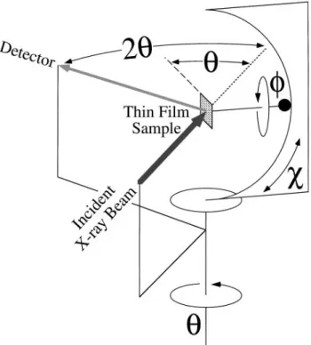
The orientation relationships between the YBa2Cu3O72d films and YSZ substrates were deter-mined using 4-circle x-ray diffraction in the Bragg – Brentano geometry and radiation from a copper x-ray tube. A schematic of the 4-circle geometry used is shown in Fig. 2. u-2u scans with the diffraction vector normal to the wafer surface were first used to establish which plane of the YBa2Cu3O72dfilm lay parallel to the (001) YSZ substrate. This was the (001) YBa2Cu3O72d plane for all of the growths discussed here (i.e., all are c-axis oriented YBa2Cu3O72d films). Then f-scans of YBa2Cu3O72d103 reflections were used to establish the
FIG. 2. A schematic diagram of a 4-circle x-ray diffractometer used to determine the epitaxial relationship between a film and a substrate.41
in-plane orientation relationship of the films with respect to the underlying substrate. As this is an inclined plane (asymmetric reflection), a component of the diffraction vector lies in the plane of the substrate. For all scans
f 0± was set parallel to the [100] YSZ direction for (001) YSZ substrates and parallel to the [001] YSZ direction for (110) YSZ substrates. This in-plane direction (f 0±) was ascertained from the location of the 011 YSZ reflection for (001) YSZ substrates and from the 100 YSZ reflection for (110) YSZ substrates. No distinction is made between the [100] YBa2Cu3O72dand [010] YBa2Cu3O72d directions in the x-ray scans nor in the deduced orientation relationships because the in-plane alignment of the [100] and [010] YBa2Cu3O72d directions is determined during growth while the YBa2Cu3O72d is tetragonal and the [100] and [010] YBa2Cu3O72d directions are equivalent.
IV. RESULTS
In order to determine the origin of the f, 69± peaks in YBa2Cu3O72d films grown on YSZ substrates, we begin by examining in detail the observation of Fork et al.7 that the deposition of a thin (,0.3 nm) BaO buffer layer prior to YBa2Cu3O72d deposition leads to a dominance of ,9±in-plane-rotated YBa2Cu3O72d grains. We present in situ RHEED characterization show-ing that the deposited BaO reacts with the YSZ sub-strate to form a ,9± in-plane-rotated (110)-oriented
BaZrO3 epitaxial reaction layer. This ,9± in-plane-rotated epitaxial alignment occurs on both (001) YSZ and (110) YSZ substrates and involves the diagonal of a rectangular surface net aligning with the diagonal of a square surface net.
We then show that at high substrate temperatures c-axis oriented YBa2Cu3O72d films grown on both (001) YSZ and (110) YSZ contain ,9± in-plane-rotated YBa2Cu3O72d domains. This implies that the
,9±rotation of the YBa
2Cu3O72d domains is inherited from the underlying,9±-rotated BaZrO3 reaction layer; growth conditions (e.g., high substrate temperatures and low growth rates) favoring the formation of the ,9± -rotated BaZrO3 reaction layer prior to the nucleation of the overlying YBa2Cu3O72d lead to an increase in
,9±-rotated YBa
2Cu3O72d domains.
Finally, we consider the underlying general mech-anism leading to this in-plane rotation. Ideal lattice constant ratios where this in-plane rotation provides the most favorable lattice match to a heteroepitaxial system are given and two additional examples of this general phenomenon, (110) (Ba, K)BiO3y(001) YSZ and (110) (Ba, K)BiO3y(001) LaAlO3, are presented.
A. Epitaxial reaction between BaO and YSZ
Due to the dramatic ability of a thin BaO buffer layer to cause ,9±in-plane rotations in the overgrown YBa2Cu3O72d layer, as demonstrated by Fork et al.,7 we began by examining the effect of such a thin BaO layer on the surface structure of (001) YSZ using in situ RHEED. Figure 3 shows the RHEED pattern observed at a ,9± in-plane rotation off the [100] YSZ azimuth after the deposition of ,1.4 nm42 of BaO on a (001) YSZ substrate at Tsub , 665±C. The pattern cannot be indexed by BaO or YSZ reflections, but it can be by BaZrO3 reflections. The RHEED pattern indicates the presence of a (110)-oriented BaZrO3 epitaxial re-action layer with two different in-plane orientations:
£
110§BaZrO
3 andf001gBaZrO3 parallel to the,9
±off [100] YSZ azimuth. An identical RHEED patterns is observed at an in-plane rotation of ,9±the other way from the [100] YSZ azimuth as well as at,69±from the [010] YSZ azimuth. This indicates the presence of a total of four equivalent in-plane (110) BaZrO3 orientations, as shown in Fig. 4(a). The lattice mismatch of these four equivalent orientation relationships is about 20.1% along the f111gBaZrO3 kf110gYSZ edge and 6.0% along
the [112gBaZrO3 kf110gYSZ edge of the near-coincident
site surface mesh cell with area 0.77 nm2, as shown for one of these equivalent orientations in Fig. 4(b). The observed orientation relationship between (110) BaZrO3 and (001) YSZ has the most favorable lattice match of all possible near-coincident surface mesh cells of equal or smaller area.
FIG. 3. RHEED pattern observed,9±off the [100] YSZ azimuth af-ter the deposition of 1.4 nm of BaO on (001) YSZ at Tsub, 665±C. A superposition of two (110) BaZrO3 orientations,f110gBaZrO3BaZrO3 azimuth (") and [001] BaZrO3azimuth (!), are indexed.
The in-plane rotation angle, f, expected for these orientations was calculated from the lattice parameters of BaZrO3 and YSZ for two limiting cases: (i) where the BaZrO3 layer is strained to be fully commensurate with the underlying YSZ substrate and (ii) where the BaZrO3 layer has fully relaxed. The result is f values of 611.3± for fully commensurate and 69.7± for fully relaxed BaZrO3 layers. As described below, it is this ,9± in-plane rotation of the (110) BaZrO3 layers that leads to the,9± in-plane rotation of the overgrown YBa2Cu3O72dlayers. Note that this angular value depends on the lattice constant of BaZrO3. As significant (,10%) variations in the lattice constant of (110) BaZrO3epitaxial reaction layers on YSZ have been observed,31 the peaks at , 69± observed in f-scans of YBa
2Cu3O72d are in qualitatively good agreement with our expectations based on this orientation relationship.
The orientation relationship shown in Fig. 4 involves the epitaxial alignment between the diagonal of a square surface net and the diagonal of a rectangular surface net (specifically the epitaxial alignment between
k111lBaZrO3 and k110lYSZ). To test the generality of
this epitaxial alignment, we also performed experiments on another orientation of YSZ containing an in-plane
k110l-type direction: (110) YSZ. In analogy to our
results on (001) YSZ, we would expect the deposition of BaO on (110) YSZ to result in the formation of a (110)-oriented BaZrO3 epitaxial reaction layer with
s110dBaZrO3 ks110dYSZ and
£
111§BaZrO3 kf110gYSZ.
The two equivalent ways in which k111lBaZrO3 can
align withk110lYSZin the nucleation of a (110) BaZrO3
(a)
(b)
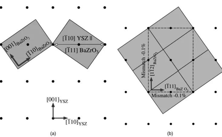
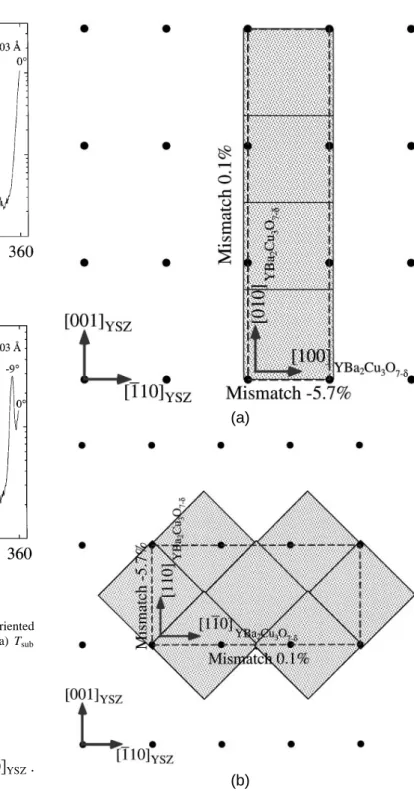
FIG. 4. Epitaxial relationship between (110) BaZrO3 and (001) YSZ showing (a) the four equivalent domains withf111gBaZrO3 kf110gYSZ and (b) the near-coincident site surface mesh cell (dashed) and its lattice match for one of the four equivalent orientations. The rectangles indicate the relaxed dimensions of the (110) BaZrO3 surface mesh with respect to the (001) YSZ substrate surface mesh (dots). layer on (110) YSZ are shown in Fig. 5(a). As shown for one of these equivalent orientations in Fig. 5(b), the lattice mismatch of these orientation relationships is about 20.1% along both edges of the near-coincident site surface mesh cell with area 0.75 nm2. This lattice match is even more favorable than that for (110) BaZrO3 on (001) YSZ and is also the most favorable lattice match of all possible near-coincident surface mesh cells of equal or smaller area. This excellent lattice match results in the expected in-plane rotation angle, f, between [001] BaZrO3 and [001] YSZ to be
(a) (b)
FIG. 5. Epitaxial relationship between (110) BaZrO3and (110) YSZ showing (a) the two equivalent domains withf111gBaZrO3 kf110gYSZand
(b) the near-coincident site surface mesh cell (dashed) and its lattice match for one of the two equivalent orientations. The rectangles indicate the relaxed dimensions of the (110) BaZrO3 surface mesh with respect to the (110) YSZ substrate surface mesh (dots).
635.3± regardless of whether the (110) BaZrO3 layer is fully commensurate or fully relaxed.
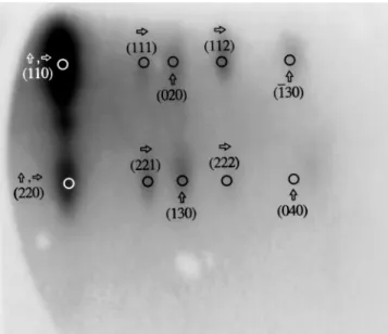
The RHEED pattern observed along the [001] YSZ azimuth after the deposition of ,1.4 nm of BaO on (110) YSZ at Tsub , 665±C is shown in Fig. 6. When viewed along the [001] BaZrO3 azimuth (,635± off the [001] YSZ azimuth) or the [¯110] BaZrO3 azimuth (,6125± off the [001] YSZ azimuth), the RHEED pattern looked identical to the corresponding BaZrO3 azimuths shown superimposed in Fig. 3. The observed RHEED patterns are consistent with the orientation relationship shown in Fig. 5. Note that for the growth of (110) BaZrO3 on (110) YSZ there are only two equiva-lent in-plane orientations because of the 2-fold symmetry of the substrate, compared to the four equivalent in-plane orientations on a (001) YSZ substrate.
B. f , 9±peaks in YBa
2Cu3O72d on (001) YSZ
Having determined how a thin BaO buffer layer dramatically alters the surface structure of (001) YSZ and (110) YSZ substrates, Yielding a,9±-rotated (110) BaZrO3 layer, we now consider the origin of the ,9± rotations observed in YBa2Cu3O72d films grown on these substrates.
In agreement with previous reports,10,11 we found f, 9± peaks to be most prevalent in YBa2Cu3O72d
FIG. 6. RHEED pattern observed along the [001] YSZ azimuth after the deposition of 1.4 nm of BaO on (110) YSZ at Tsub ,665±C. Along this azimuth, both of the equivalent (110) BaZrO3orientations shown in Fig. 5 give rise to the same set of spots. These BaZrO3 spots are indexed, as well as two spots due to the YSZ substrate.
films grown at high substrate temperatures. With in-creasing substrate temperature, the reaction between YBa2Cu3O72d and YSZ occurs more rapidly, until at
FIG. 7. f-scan of 103 YBa2Cu3O72d peaks of c-axis oriented
YBa2Cu3O72d film grown on (001) YSZ grown by PLD at Tsub
, 780±C.
some point the BaZrO3 reaction layer forms prior to the nucleation of the YBa2Cu3O72d. The same event will occur at a fixed growth temperature as the growth rate is lowered, since the reaction then has more time to transpire. Such an event will lead to ,9± in-plane rotations of (110) BaZrO3 grains; the epitaxial sequence is identical to the BaO 1 YSZ case described above. Of course, microscopically there may be regions where the YBa2Cu3O72d nucleates prior to the formation of BaZrO3 and regions where BaZrO3 nucleates prior to the YBa2Cu3O72d. In such cases, a mixture of 0±, 45±, and ,9± in-plane rotations can be expected to occur. This is the typical observation for YBa2Cu3O72d films grown on (001) YSZ substrates at high temperatures, an example of which is shown in Fig. 7.
The results of Fork et al.7 on how thin BaO buffer layers deposited on YSZ (001) lead to a dramatic in-crease in ,9± in-plane-rotated YBa2Cu3O72d grains, together with the above in situ observations of the ensuing epitaxial reaction, indicate the full orientation re-lationship between the c-axis oriented YBa2Cu3O72d, the (110) BaZrO3epitaxial reaction layer, and the underlying (001) YSZ substrate is
s001dYBa2Cu3O72d k s110dBaZrO3 k s001dYSZ,
f100gYBa2Cu3O72d kf001gBaZrO3,
and £111§BaZrO3 kf110gYSZ. Cross-sectional TEM studies have shown that con-strained (110)-oriented BaZrO3, i.e., BaZrO3 formed after the epitaxial alignment between YBa2Cu3O72d and YSZ is established, epitaxially aligns with c-axis oriented YBa2Cu3O72d in the following manner19,31:
s001dYBa2Cu3O72d k s110dBaZrO3
and f110gYBa2Cu3O72d kf001gBaZrO3.
This orientation relationship is not the same as that in-ferred from the in-plane orientation of the,9±domains in c-axis YBa2Cu3O72d films grown on (001) YSZ. The above orientation relationship would be manifested by peaks at f , 36±and equivalent angles, rather than the observed peaks at f , 9±. Our in situ observations of the in-plane orientation of (110) BaZrO3 on (001) YSZ together with the observation of peaks at f , 9± and symmetrically equivalent angles indicate that the orien-tation relationship between unconstrained (110)-oriented BaZrO3 and c-axis oriented YBa2Cu3O72d is
s001dYBa2Cu3O72d ks110dBaZrO3
and f100gYBa2Cu3O72d kf001gBaZrO3
on (001) YSZ substrates. Interestingly, both of these variants have identical lattice match19(2.6% and 8.8% mismatch along the surface mesh cell edge directions), as shown in Fig. 8. The near-coincident site surface mesh cell area is 0.94 nm2 for the former orientation relation-ship and half this for the latter orientation relationrelation-ship. Because of its smaller area,43 the latter orientation re-lationship (indicated by peaks at f , 9±, rather than
f , 36±) is dominant, as expected. As described be-low, sometimes both variants are seen in the same film, yielding not only peaks at f , 9±, but also peaks at
f , s45±2 9±d 36±.11
C. f, 9±peaks in YBa2Cu3O72d on (110) YSZ
In our model the origin of ,9± in-plane-rotated YBa2Cu3O72d domains is due to a ,9±-rotated (110) BaZrO3 epitaxial reaction layer. As shown above (Fig. 5), a,9±in-plane-rotated (110) BaZrO3 layer also occurs on (110) YSZ substrates. We thus investigated the growth of (001) YBa2Cu3O72d on (110) YSZ to see if, at growth conditions favoring the formation of a BaZrO3 reaction layer prior to the nucleation of the overlying YBa2Cu3O72d, in-plane rotation of the YBa2Cu3O72d domains would also be observed, as predicted by our model.
The growth of c-axis oriented YBa2Cu3O72d films has been reported on (001)-, (110)-, and (111)-oriented YSZ substrates as well as on mis(111)-oriented YSZ substrates.8,20,30,32,44 However, the in-plane orientation of YBa2Cu3O72d deposited on (110) YSZ substrates has not been previously reported. As shown in Figs. 9 and 10, YBa2Cu3O72d grows c-axis oriented with in-plane rotations of 0±,,9±, and 45±on (110) YSZ. The relative fraction of these in-plane orientations depends on the substrate temperature during growth. At lower temperature, Fig. 10(a), the f 0± peaks dominate; at higher substrate temperature, Fig. 10(b), peaks at
,9± and 45± are also observed. The 0± and 45± in-plane rotations are the orientations expected from lattice match considerations when YBa2Cu3O72d nucleates
(a) (b)
FIG. 8. Epitaxial relationship between (001) YBa2Cu3O72dand (110) BaZrO3showing the near-coincident site surface mesh cell (dashed) and its lattice match for (a)f010gYBa2Cu3O72d kf001gBaZrO3, and (b)f110gYBa2Cu3O72d kf001gBaZrO3. The squares indicate the relaxed dimensions of the (001) YBa2Cu3O72dsurface mesh with respect to the (110) BaZrO3surface mesh (rectangles) on the (001) YSZ substrate surface mesh (dots).
directly on (110) YSZ. As shown in Fig. 11, the 0± relationship has a lattice mismatch of 25.7% along the f100gYBa2Cu3O72d kf110gYSZ edge and a mismatch
of 0.1% along the f010gYBa2Cu3O72d kf001gYSZ edge
of a near-coincident site surface mesh cell with area 0.58 nm2. The 45±relationship has the identical lattice mismatch and near-coincident site surface mesh cell area: 25.7% along thef110gYBa2Cu3O72d kf001gYSZedge,
0.1% along the£110§YBa
2Cu3O72d k
£
110§YSZedge, and an area of 0.58 nm2. However, if only the oxygen sublattice is considered, the 0±orientation relationship has a near-coincident site surface mesh cell area half the size (0.29 nm2) of the 45±orientation relationship, explaining the dominance of the 0±peaks compared to the 45±peaks in the f-scans. The observation of more ,9±peaks at higher substrate temperature is analogous to the growth of YBa2Cu3O72d on (001) YSZ and expected from the increased likelihood of (110) BaZrO3 formation before nucleation of the overlying YBa2Cu3O72d.
Combining the RHEED results indicating the epi-taxial orientation of the (110) BaZrO3 layer on (110) YSZ (see Fig. 5) with the f-scan results [see Fig. 10(b)],
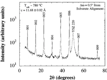
FIG. 9. u-2u scan of a c-axis oriented YBa2Cu3O72dfilm grown on
(110) YSZ by sputtering at Tsub , 780±C. This scan was made after rocking 0.5±in omega off alignment to the (110) YSZ substrate.
the following orientation relationship is implied between the c-axis oriented YBa2Cu3O72d, the (110) BaZrO3 epitaxial reaction layer, and the underlying (110) YSZ
(a)
(b)
FIG. 10. f-scans of 103 YBa2Cu3O72d peaks of c-axis oriented
YBa2Cu3O72d films grown on (110) YSZ by sputtering at (a) Tsub
, 750±C and (b) T
sub , 780±C. substrate:
s001dYBa2Cu3O72d k s110dBaZrO3 k s110dYSZ,
f110gYBa2Cu3O72d kf001gBaZrO3,
and £111§BaZrO
3 kf110gYSZ.
Note that the in-plane orientation between YBa2Cu3O72d and BaZrO3 differs by a 45±in-plane rotation from that observed on (001) YSZ. Although the lattice mismatch is identical for both of these orientation relationships, the reason for the preference of the variant with the larger near-coincident site surface mesh cell area43 on (110) YSZ is unclear. In both cases, (001) YBa2Cu3O72d is nucleating on (110) BaZrO3. The clear dependence of the orientation relationship on the layer underlying the (110) BaZrO3 [i.e., (001) YSZ or (110) YSZ] leads us to speculate that the step structure of the (110) BaZrO3 layer, which is in turn dependent on the step structure of
(a)
(b)
FIG. 11. Epitaxial relationship between (001) YB2Cu3O72d and
(110) YSZ showing the near-coincident site surface mesh cell (dashed) and its lattice match for (a) f010gYBa2Cu3O72d kf001gYSZ
and (b)f110gYBa2Cu3O72d kf001gYSZ. The squares indicate the relaxed dimensions of the (001) YBa2Cu3O72d surface mesh with respect to
the (110) YSZ substrate surface mesh (dots).
the underlying YSZ substrate orientation, is responsible for the dominance of one orientation relationship over the other. The importance of graphoepitaxy on the 45± in-plane orientation of (001) YBa2Cu3O72d on (001) YSZ has been noted.9 We believe that graphoepitaxy is also playing a role in the ,9±in-plane orientation.
The in-plane orientation observations are in accord with our model and difficult to explain by other means. For example, just as a near-coincident site lattice model between (001) YBa2Cu3O72d and (001) YSZ [i.e., with-out the prior formation of an intermediate (110) BaZrO3 reaction layer] was inadequate to explain the occurrence of the,9±orientation,11it is also incapable of predicting ,9±domains in (001) YBa
2Cu3O72don (110) YSZ. The low-mismatch, low-S criterion used to select favorable orientations from near-coincident site lattices and meshes leads to the prediction that other orientations that are not seen should be observed, rather than the observed ,9± in-plane-rotated orientation.
D. Other examples of general phenomenon
The formation of ,9±in-plane-rotated domains in c-axis oriented YBa2Cu3O72dfilms grown on (001) YSZ and (110) YSZ are just two examples of a general heteroepitaxial phenomenon. This phenomenon, involv-ing the epitaxial alignment between the diagonal of a square surface mesh and the diagonal of a rectangular surface mesh, is a general method for producing in-plane misorientations. Here we describe the ideal lattice constant ratios where this phenomenon is expected to occur for a (110)y(001) interface between two cubic structures. Extension of this epitaxial alignment concept to the relevant surface meshes of other planes and lattices is straightforward. Additional examples of this phenomenon are then presented.
For a (110)-oriented film of a material with a simple cubic lattice with lattice constant afilm on a (001)-oriented substrate having a face-centered cubic (fcc) lattice with lattice constant afcc sub, this match along the diagonals occurs whenp3afilm
p
2afcc sub, or afilm >
0.816 afcc sub. For comparison, the afilmyafcc sub ratio for (110) BaZrO3 on (001) YSZ is 0.816 (at room tem-perature). However, minimizing the mismatch along the diagonal does not minimize the lattice mismatch of the near-coincident site surface mesh. To minimize the latter, it is desired to minimize the lattice mismatch along two orthogonal directions, as can be seen from Fig. 4(b). The ideal lattice constant of the film (that minimizes the lattice match along two orthogonal directions) is attained when afilm 2
p 3s3
p
2 2 4dafcc sub, or afilm >
0.841 afcc sub. Alternatively, if the (001)-oriented sub-strate has a simple cubic lattice with lattice constant asub, the corresponding value is afilm 4
p
3s3 2 2p2dasub, or afilm > 1.189 asub. In both of these cases, the mini-mized lattice mismatch is 2.9% (12.9% in one direction and 22.9% in the perpendicular direction).
A more favorable lattice match can be achieved along two orthogonal directions when this phenome-non occurs between a oriented film and a (110)-oriented substrate of two cubic materials. In this case, the ideal lattice constant of the film is attained in two
orthogonal directions at the same time (i.e., perfect lattice match) when afilm
p
2y3afcc sub, or afilm >
0.816 afcc sub. As Fig. 5(b) shows, (110) BaZrO3on (110) YSZ is nearly this ideal case: afilmyafcc sub 0.816 (at room temperature). Alternatively, if the (110)-oriented substrate has a simple cubic lattice, the ideal value is afilm
°
2yp3¢asub, or afilm > 1.155 asub.
From the above discussion, the ideal lattice parameter of a (110)-oriented simple cubic material for growth on (001) YSZ in order to observe this phenomenon is 4.319 ˚A. Ba12xKxBiO3 has a lattice constant of 4.322 ˚A to 4.287 ˚A over the composition
range where its structure is simple cubic s0.1 & x &
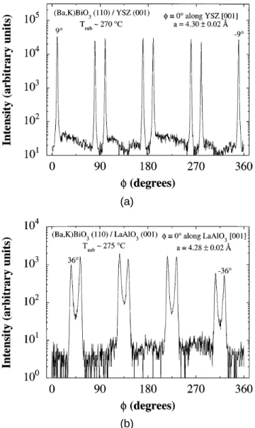
0.4d.45,46 In hopes of observing another example of this phenomenon, involving the epitaxial alignment between the diagonal of a square surface mesh and the diagonal of a rectangular surface mesh, (110) (Ba, K)BiO3 was grown on (001) YSZ. This growth was initiated at Tsub , 550±C with the nucleation of BaBixOy sx , 1d for 5 min (,10 nm).39,47. Then the substrate temperature was lowered to ,270±C and (Ba, K)BiO3 was grown. As expected, sharp peaks at f , 69± were observed [see Fig. 12(a)]. Note, however, that the lattice parameter of (Ba, K)BiO3 is quite close to that of BaZrO3 (4.193 ˚A).17 Although no x-ray diffraction peaks arising from (110) BaZrO3 were detected, it is possible that an epitaxial reaction occurred between (Ba, K)BiO3 and YSZ forming a thin (110) BaZrO3 reaction layer, upon which the (Ba, K)BiO3 layer subsequently grew.
An example of this same epitaxial phenomena be-tween a simple cubic substrate and simple cubic film is (110) (Ba, K)BiO3 on (001) LaAlO3,48 as shown in Fig. 12(b). Although the epitaxial alignment giving rise to the in-plane rotation is the same as that shown for YSZ in Fig. 4, here the peaks occur at f , s45 2 9d
36± because the LaAlO3 surface mesh is not centered, resulting in a 45±rotation of the in-plane axes compared to the (001) YSZ surface mesh. The afilmyasub ratio for (110) (Ba, K)BiO3 on (001) LaAlO3 is 1.13, compared to the ideal value of 1.189 discussed above.
V. DISCUSSION
Having investigated the origin of the f, 69± peaks, we reexamine the results presented by others related to ,9± peaks in (001) YBa2Cu3O72d films deposited on (001) YSZ. Our explanation, involving the epitaxial alignment between the diagonal of a square surface mesh and the diagonal of a rectangular surface mesh, is consistent with prior results and clarifies unexplained and previously unexpected observations. For example, Fork et al.7 showed that the in-plane orientation of overlying YBa2Cu3O72d layers was sensitively dependent on the deposition of extremely thin
(a)
(b)
FIG. 12. f-scans of 200 (Ba, K)BiO3 peaks of (110)-oriented (Ba, K)BiO3films grown by MBE on (a) (001) YSZ at Tsub, 270±C
and (b) (001) LaAlO3 at Tsub, 275±C.
layers (,0.3 nm) of BaO, CuO, Y2O3, or BaZrO3 on (001) YSZ substrates, or on (001) YSZ substrates upon which a homoepitaxial YSZ layer was grown. The thin CuO, Y2O3, and BaZrO3 layers and the homoepitaxial YSZ layer favored the 45±in-plane rotation, whereas the BaO layer led to the ,9± in-plane rotation. Although this previous study lacked in situ characterization during the deposition of these thin layers, our in situ RHEED observations indicate the reason for the extreme sensitivity of the in-plane orientation to BaO deposition: it leads to a ,9± rotated (110) BaZrO3 epitaxial reaction layer, which subsequently determines the in-plane orientation of the YBa2Cu3O72d overlayer. We have not studied the interfacial reactions of CuO or Y2O3 overlayers, but in contrast to the BaO – ZrO2 case, the CuO–ZrO2 phase diagram49 is free of intermediate phases and the Y2O3– ZrO2 phase diagram50 not only
contains a very wide solid solution region (up to 40 mol % Y2O3), but the only intermediate compound,50 Zr3Y4O12, forms so sluggishly that single-phase YSZ films with up to 78 mol % Y2O3 have been reported.51 Thus, of the thin layers deposited by Fork et al.,7 an interfacial reaction layer is expected only for the case of BaO. The resultant (110)-oriented BaZrO3 reaction layer subsequently leads to the dominant ,9± in-plane rotation observed in the overgrown YBa2Cu3O72d film. Given the strong influence of the (110) BaZrO3 interfacial reaction layer on the resulting in-plane orien-tation of the YBa2Cu3O72d, it may seem surprising that the thin BaZrO3 layer deposited in the aforementioned study7 did not also lead to YBa2Cu3O72d domains with a ,9±in-plane rotation. We attribute this to the growth of a non-(110) oriented BaZrO3 layer. Fork et al.7 did not report the orientation of their thin BaZrO3 layers. However, we found that BaZrO3films deposited on (001) YSZ were mainly oriented in the cube-on-cube orien-tation, i.e., with (001) BaZrO3 parallel to (001) YSZ, in contrast to the (110) BaZrO3 orientation formed by epitaxial reaction. Others have reported (110)-oriented BaZrO3 films deposited on (001) YSZ,3,52 but they also report that the inverted interface, i.e., (001) YSZ deposited on (001) BaZrO3, grows cube-on-cube.3As the epitaxial relationship obtained for the growth of BaZrO3 on (001) YSZ and vice versa varies significantly with deposition conditions, it would appear from the absence of ,9± domains in the YBa2Cu3O72d films grown on top of a BaZrO3 buffer layer by Fork et al.7 that their BaZrO3 layer was not (110)-oriented.
The predominant 45± in-plane rotation observed by Fork et al.7 for YBa
2Cu3O72d films grown on (001) YSZ substrates with homoepitaxial YSZ buffer layers is consistent with the work of Brorsson et al.9 Brorsson et al.9 showed that homoepitaxial YSZ layers, grown under conditions similar to those used by Fork et al.,7 have an increased surface step density compared to the underlying YSZ substrate. They found that an increased step density on the surface of (001) YSZ, regardless of whether it was from a homoepitaxial YSZ film or a result of high temperature annealing of the substrate, led to an increased fraction of 45± in-plane-rotated YBa2Cu3O72d grains in the overlying film. Brorsson et al.9interpreted this result to imply that step edges on (001) YSZ substrates act as favorable nucleation sites for 45±-oriented YBa2Cu3O72d.9 Since no reactions between the thin (,0.3 nm) CuO and Y2O3 layers deposited by Fork et al.7 on (001) YSZ are expected, an analogous surface roughening and graphoepitaxial mechanism may take place, leading to the observed increase in 45± in-plane-rotated YBa2Cu3O72d grains for these buffer layers as well.
Similar to the growth temperature effect reported for the growth of YBa2Cu3O72d on (001) YSZ,10,11
in our growths on (110) YSZ substrates, the f, 9± domains were observed at higher growth temperatures. This is consistent with the epitaxial relationship of the YBa2Cu3O72dlayer being established after the formation of the BaZrO3 interfacial layer. Lower growth tempera-tures were free of f , 9±domains, consistent with the epitaxial relationship of the YBa2Cu3O72d layer being established before the formation of the BaZrO3 layer.
Wen et al.8 present a cross-sectional TEM image (Fig. 6 in Ref. 8) of a BaZrO3epitaxial in-plane reaction product between (001) YBa2Cu3O72d and (001) YSZ that appears to be close to the ,9± rotation that we have seen by RHEED. Their cross-sectional TEM image is along the [100] YSZ zone axis, and they state that this substrate zone-axis is approximately parallel to the [331] direction of the BaZrO3 layer. This is within 3.5± of the (irrational) direction in BaZrO3 that lies parallel to [100] YSZ (see Fig. 4) for fully relaxed BaZrO3. Unfortunately, Wen et al.8 do not indicate if the BaZrO3 layer is (110)-oriented. However, it is clear that it must be different than the (001)-oriented BaZrO3 layers that are present in the remainder of their TEM images as
h001j cannot be perpendicular to [331].
Recently peaks at f, 637± have also been re-ported in c-axis oriented YBa2Cu3O72d films grown on (001) YSZ, indicating the presence of YBa2Cu3O72d grains with in-plane rotations of about 37±.11These peaks are observed in films grown under conditions similar to those in which peaks at f, 9±occur (i.e., high sub-strate temperatures). In fact, both the f, 9±peaks and the f, 37±peaks were observed in the same film by Skofronick et al.11 The origin of these ,37± in-plane-rotated grains is likely the same as that of the,9±rotated grains. c-axis oriented YBa2Cu3O72d is known to align epitaxially with (110)-oriented BaZrO3 in two manners, related by a 45±in-plane rotation. The first is
s001dYBa2Cu3O72d k s110dBaZrO3
and f100gYBa2Cu3O72d kf001gBaZrO3,
as we have found to be dominant for the nucleation of YBa2Cu3O72d on BaZrO3 on (001) YSZ, and the second is
s001dYBa2Cu3O72d k s110dBaZrO3
and f110gYBa2Cu3O72d kf001gBaZrO3
as others19,31 have observed for BaZrO
3 formed after the epitaxial alignment between YBa2Cu3O72d and YSZ is established. We have found the second to be dominant for the nucleation of YBa2Cu3O72d on BaZrO3 on (110) YSZ. As discussed earlier, both of these orientation relationships have identical lattice match, and we speculate that the dominance of a particular one is due to a graphoepitaxial contribu-tion. The presence of both ,9± and ,37± in-plane
rotations in the YBa2Cu3O72d films of Skofronick et al.,11 in contrast to the more frequent observa-tion of solely f , 9± peaks, provides further evi-dence that an influencing factor other than lattice match alone is active. The more frequent ob-servation of the f, 9± peaks compared to the
f , 37± (or 45±2 9± 36±) peaks indicates that the
f100gYBa2Cu3O72d kf001gBaZrO3 orientation is dominant
for the growth conditions most frequently used to deposit (001) YBa2Cu3O72d on (001) YSZ.
VI. CONCLUSIONS
The epitaxial alignment between the diagonal of a square surface mesh and the diagonal of a rectangular surface mesh is a general method for producing in-plane misorienations. The model presented explains why diffraction peaks at f , 9± are observed in c-axis oriented YBa2Cu3O72d grown on (001) YSZ as well as on (110) YSZ substrates, and has been used to select other epitaxial systems to demonstrate this phenomenon. If a means could be found to suppress all but one of the ,9± in-plane-rotated domains, this technique could provide a significant advantage in grain boundary engineering over the bi-epitaxy process for the growth of YBa2Cu3O72d-based and (Ba, K)BiO3-based Josephson junctions.
ACKNOWLEDGMENTS
We gratefully acknowledge helpful interactions with J. Str ¨obel, G. L. Skofronick, and A. H. Carim, and Joe Wenckus for generously supplying yttria-stablized cu-bic zirconia crystals. DGS acknowledges the financial support of ONR through Contract N00014-93-1-0512. JCC acknowledges the financial support of NSF through Grant DMR-9357614.
REFERENCES
1. A. J. Moulson and J. M. Herbert, Electroceramics: Materi-als ≤ Properties ≤ Applications (Chapman & Hall, London, 1990). 2. K. Char, M. S. Colclough, S. M. Garrison, N. Newman, and G. Zaharchuk, Appl. Phys. Lett. 59, 733 (1991); K. Char, M. S. Colclough, L. P. Lee, and G. Zaharchuk, Appl. Phys. Lett. 59, 2177 (1991).
3. X. D. Wu, L. Luo, R. E. Muenchausen, K. N. Springer, and S. Foltyn, Appl. Phys. Lett. 60, 1381 (1992).
4. L. P. Lee, K. Char, M. S. Colclough, and G. Zaharchuk, Appl. Phys. Lett. 59, 3051 (1991).
5. D. K. Fork, A. Barrera, T. H. Geballe, A. M. Viano, and D. B. Fenner, Appl. Phys. Lett. 57, 2504 (1990).
6. S. M. Garrison, N. Newman, B. F. Cole, K. Char, and R. W. Barton, Appl. Phys. Lett. 58, 2168 (1991); S. M. Garrison, N. Newman, B. F. Cole, K. Char, and R. W. Barton, Appl. Phys. Lett. 59, 3060 (1991).
7. D. K. Fork, S. M. Garrison, M. Hawley, and T. H. Geballe, J. Mater. Res. 7, 1641 (1992).
8. J. G. Wen, C. Traeholt, H. W. Zandbergen, K. Joosse, E. M. C. M. Reuvekamp, and H. Rogalla, Physica C 218, 29 (1993).
9. G. Brorsson, E. Olsson, Z. G. Ivanov, E. A. Stepantsov, J. A. Alarco, Y. Boikov, T. Claeson, P. Berastegui, V. Langer, and M. L¨ofgren, J. Appl. Phys. 75, 7958 (1994).
10. Y. Boikov, Z. G. Ivanov, G. Brorsson, and T. Claeson, Supercond. Sci. Technol. 7, 281 (1994).
11. G. L. Skofronick, A. H. Carim, S. R. Foltyn, and R. E. Muen-chausen, J. Appl. Phys. 76, 4753 (1994).
12. D. Dimos, P. Chaudhari, and J. Mannhart, Phys. Rev. B 41, 4038 (1990).
13. S. S. Laderman, R. C. Taber, R. D. Jacowitz, J. L. Moll, C. B. Eom, T. L. Hylton, A. F. Marshall, T. H. Geballe, and M. R. Beasley, Phys. Rev. B 43, 2922 (1991).
14. J. A. Alarco, G. Brorsson, Z. G. Ivanov, P- ˚A. Nilsson, E. Olsson, and M. L¨ofgren, Appl. Phys. Lett. 61, 723 (1992).
15. R. D. Shannon, Acta Crystallogr. A 32, 751 (1976).
16. R. P. Ingel and D. Lewis, III, J. Am. Ceram. Soc. 69, 325 (1986). 17. JCPDS card 6-399 (JCPDS International Centre for Diffraction
Data, Swarthmore, PA).
18. R. Beyers and T. M. Shaw, Solid State Phys. 42, 135 (1989), and references therein.
19. G. L. Skofronick, A. H. Carim, S. R. Foltyn, and R. E. Muen-chausen, J. Mater. Res. 8, 2785 (1993).
20. C. H. Mueller, P. H. Holloway, J. D. Budai, F. A. Miranda, and K. B. Bhasin, J. Mater. Res. 10, 810 (1995).
21. The lattice mismatch values given throughout this article are calculated by the formula sasub2 afilmyafilmd.22 Although the
lattice constants vary with temperature and composition (0.095 <
x < 0.6 insY2O3dxsZrO2d12x and 0 < d < 1 in YBa2Cu3O72d)
and it would be most appropriate to report the lattice mismatch for the specific growth conditions used, for simplicity we report the lattice mismatch at room temperature, x, 0.09516and d,
0.18 These approximate values are adequate for the relatively qualitative reasoning that lattice mismatch considerations allow. 22. See, for example, J. W. Matthews in Epitaxial Growth, Part B,
edited by J. W. Matthews (Academic Press, New York, 1975), pp. 559 – 609.
23. D. G. Schlom, E. S. Hellman, E. H. Hartford, Jr., and J. Mannhart, presented at the Fall ‘93 Materials Research Society Meeting in Boston, MA, 1993 (unpublished).
24. J. J. Cuomo, M. F. Chisholm, D. S. Yee, D. J. Mikalsen, P. B. Madakson, R. A. Roy, E. Giess, and G. Scilla, in Thin Film Processing and Characterization of High-Temperature Supercon-ductors, AIP Conference Proceedings No. 165, edited by J. M. E. Harper, R. J. Colton, and L. C. Feldman (American Institute of Physics, New York, 1988), pp. 141 – 148.
25. T. Komatsu, O. Tanaka, K. Matusita, M. Takata, and T. Ya-mashita, Jpn. J. Appl. Phys. 27, L1025 (1988).
26. H. Koinuma, K. Fukuda, T. Hashimoto, and K. Fueki, Jpn. J. Appl. Phys. 27, L1216 (1988).
27. M. J. Cima, J. S. Schneider, S. C. Peterson, and W. Coblenz, Appl. Phys. Lett. 53, 710 (1988).
28. C. T. Cheung and E. Ruckenstein, J. Mater. Res. 4, 1 (1989). 29. L. A. Tietz, C. B. Carter, D. K. Lathrop, S. E. Russek, R. A.
Buhrman, and J. R. Michael, J. Mater. Res. 4, 1072 (1989). The 0.3 nm fringe spacing reported for the intermediate reaction layer in the cross-sectional TEM image (identified as being possibly BaZrO3) indicates that the BaZrO3 is (110)-oriented.
30. M. J. Shapiro, K. L. More, W. J. Lackey, J. A. Hanigofsky, D. N. Hill, W. B. Carter, E. K. Barefield, E. A. Judson, D. F. O’Brien, R. Patrick, Y. S. Chung, and T. S. Moss, J. Am. Ceram. Soc. 74, 2021 (1991).
31. D. M. Hwang, Q. Y. Ying, and H. S. Kwok, Appl. Phys. Lett. 58, 2429 (1991).
32. M. J. Casanove, A. Alimoussa, C. Roucau, C. Escribe-Filippini, P. L. Reydet, and P. Marcus, Physica C 175, 285 (1991).
33. O. Eibl, K. Hradil, and H. Schmidt, Physica C 177, 89 (1991). 34. J. A. Alarco, G. Brorsson, H. Olin, and E. Olsson, J. Appl. Phys.
75, 3202 (1994).
35. Ceres Corp., N. Billerica, Massachusetts. 36. Commercial Crystal Laboratories, Naples, Florida.
37. X. X. Xi, G. Linker, O. Meyer, E. Nold, B. Obst, F. Ratzel, R. Smithey, B. Strehlau, F. Weschenfelder, and J. Geerk, Z. Phys. B 74, 13 (1989).
38. B. Holzapfel, B. Roas, L. Schultz, P. Bauer, and G. Saemann-Ischenko, Appl. Phys. Lett. 61, 3178 (1992).
39. E. S. Hellman, E. H. Hartford, and E. M. Gyorgy, Appl. Phys. Lett. 58, 1335 (1991).
40. C. B. Eom, J. Z. Sun, K. Yamamoto, A. F. Marshall, K. E. Luther, T. H. Geballe, and S. S. Laderman, Appl. Phys. Lett. 55, 595 (1989).
41. L. V. Az´aroff, Elements of X-Ray Crystallography (McGraw-Hill, New York, 1968), pp. 360 – 389.
42. With the oxygen plasma on, the sample was exposed to the barium beam for 40 s. RBS measurement of the resulting BaO film thickness deposited on a comounted MgO substrate (Tsub,
660±C) indicated an average BaO film thickness of 1.4 nm. 43. Note that depending on the surface termination of the (110)
BaZrO3 layer, the oxygen sublattice of this latter orientation re-lationshipsf110gYBa2Cu3O72dkf001gBaZrO3d could have the same
surface mesh area as the oxygen sublattice of the former orienta-tion relaorienta-tionshipsf100gYBa2Cu3O72d kf001gBaZrO3d. There are two
distinct (110) BaZrO3planes, neither of which is charge neutral: BaZrO and O2. If the latter is the terminating layer, the oxygen sublattice of the near-coincident site surface mesh cell shown in Fig. 8 is centered, and the primitive cell would have an area of 0.47 nm2.
44. C. Escribe-Filippini, P. L. Reydet, J. Marcus, and M. Burnel, J. Less-Comm. Met. 151, 263 (1989).
45. L. F. Schneemeyer, J. K. Thomas, T. Siegrist, B. Batlogg, L. W. Rupp, R. L. Opila, R. J. Cava, and D. W. Murphy, Nature (Lon-don) 335, 421 (1988).
46. J. P. Wignacourt, J. S. Swinnea, H. Steinfink, and J. B. Goode-nough, Appl. Phys. Lett. 53, 1753 (1988).
47. M. G. Norton, E. S. Hellman, E. H. Hartford, Jr., and C. B. Carter, Physica C 205, 347 (1993); M. G. Norton, E. S. Hellman, E. H. Hartford, Jr., and C. B. Carter, J. Cryst. Growth 113, 716 (1991). 48. Landolt – B¨orstein: Numerical Data and Functional Relationships in Science and Technology, New Series, Group III, Vol. 12a, edited by K-H. Hellwege (Springer-Verlag, Berlin, 1978), p. 160. At room temperature LaAlO3 is rhombohedral (not simple cubic). However, the distortion from simple cubic is extremely small sa 60.1±d vs. a 60±for cubic). Furthermore, at the
sub-strate temperature at which growth was initiated, Tsub, 550±C,
LaAlO3 is cubic.
49. A. M. M. Gadalla and J. White, Trans. Brit. Ceram. Soc. 65, 383 (1966).
50. V. S. Stubican, R. C. Hink, and S. P. Ray, J. Am. Ceram. Soc.
61, 17 (1978); V. S. Stubican and J. R. Hellmann, in Science
and Technology of Zirconia, Vol. 3 in Advances in Ceramics series, edited by A. H. Heuer and L. W. Hobbs (American Ceramic Society, Westerville, OH, 1981), pp. 25 – 36.
51. H. Holzschuh and H. Suhr, Appl. Phys. Lett. 59, 470 (1991). 52. D. K. Fork (private communication). These (110) BaZrO3 films
were deposited on (001) YSZ on (001) Si. They were much thicker than the,0.3 nm BaZrO3buffer layers studied in Ref. 7. Interestingly, a f-scan of these (110)-oriented BaZrO3 films on (001) YSZ revealed two in-plane orientation variants rotated with respect to one another by 9.5±!