HAL Id: hal-01577164
https://hal.archives-ouvertes.fr/hal-01577164
Submitted on 25 Aug 2017
HAL is a multi-disciplinary open access
archive for the deposit and dissemination of sci-entific research documents, whether they are pub-lished or not. The documents may come from teaching and research institutions in France or abroad, or from public or private research centers.
L’archive ouverte pluridisciplinaire HAL, est destinée au dépôt et à la diffusion de documents scientifiques de niveau recherche, publiés ou non, émanant des établissements d’enseignement et de recherche français ou étrangers, des laboratoires publics ou privés.
To cite this version:
Susan Stepney, Paul Andrews. EvoEvo Deliverable 4.2: Computational model requirements specifi-cation. [Research Report] INRIA Grenoble - Rhône-Alpes. 2015. �hal-01577164�
EvoEvo Deliverable 4.2
Computational model requirements specification
Due date: M18 (April 2015)
Person in charge: Susan Stepney
Partner in charge: University of York (UoY)
Workpackage: WP4 (A computational EvoEvo framework)
Deliverable description: Computational model for EvoEvo describing the design of the EvoEvo framework. Shows how the metamodel in D4.1 is instantiated.
Revisions:
Revision no. Revision description Date Person in charge
1.0 Initial version of deliverable 26/04/15 P. Andrews (UoY)
1.1 review and minor modifications 28/04/15 S. Stepney (UoY) 1.2 Figures corrected from review comments 3/07/15 S. Stepney (UoY)
Table of Contents
1. INTRODUCTION 3
2. COSMOS METHODOLOGY AND ENGINEERED DOMAINS 3
3. FRAMEWORK SPECIFICATION 6
3.1. TOP-LEVEL FRAMEWORK 6
3.2. INSTANTIATING THE EVOEVO METAMODEL FROM THE FRAMEWORK LIBRARY 9 3.3. INSTANTIATING EXPERIMENT AND VIEWS FROM THE FRAMEWORK LIBRARY 14
4. APPLYING THE FRAMEWORK 15
4.1. OVERVIEW 15
4.2. SPECIFYING MACHINES 16
4.3. SPECIFYING THE PROBLEM 16
4.4. SPECIFYING THE ORGANISM AND WORLD 17
4.5. SPECIFYING THE INSTRUMENTATION 18
5. NEXT STEPS 18
1. Introduction
The role of work-package (WP) 4 is to build suitable computational analogues of the biologically-oriented EvoEvo mechanisms identified by WP2 and WP3. These computational analogues will form the basis of the EvoEvo computational framework that will enable the development of novel evolutionary engineered systems, demonstrated in WP5.
The computational framework is based on a metamodel that captures the core EvoEvo concepts. This metamodel is presented in the WP4 deliverable D4.1, providing a suitable abstraction of the biological EvoEvo concepts, in particular those concepts presented in the integrated EvoEvo model in deliverable D2.7.
The objectives of WP4 are:
1. to define a computational metamodel of EvoEvo, by abstracting and interpreting the biological model in a form suitable for in silico implementation;
2. to instantiate the metamodel into a computational model suitable for specifying demonstrator applications of EvoEvo;
3. to implement the computational model as an executable computational platform, suitable for developing demonstrator applications of EvoEvo.
This deliverable, D4.2, addresses the second objective, and presents an instantiation of the metamodel from D4.1 into a computational model. Specifically, we augment the metamodel with non-biological components needed for application development and experimentation, including instrumentation, analysis, user interface, and configuration facilities.
In section 2 we recap the CoSMoS methodology that has guided our approach to developing and instantiating the EvoEvo metamodel. We then show how the metamodel can be used to define an EvoEvo platform model that forms the design specification for the computational EvoEvo framework. In section 4 we discuss how the user can then specify the components of the computation framework they wish to have in the EvoEvo algorithm instances. We conclude by summarising how the EvoEvo framework will be implemented to achieve objective 3 of WP4.
2. CoSMoS Methodology and Engineered Domains
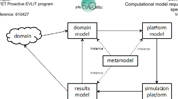
In section 2 of D4.1 we summarise the CoSMoS approach that acts as our methodology for developing and instantiating the EvoEvo metamodel. Figure 1 here summarises the relationship between the three CoSMoS model components (domain model, platform model, and results model) and their metamodel. This shows how each model can be considered an instance of (part of) the same unifying metamodel, as they capture the same core concepts. This does not mean that the models are identical, only that they are cast in the same language. D4.1 establishes such a metamodel for EvoEvo upon which we base the EvoEvo computational framework specified in this deliverable.
Figure 1. Relationship between the core CoSMoS components and their metamodel.
The CoSMoS approach discussed so far has been developed to assist the engineering of simulations of real-world domains. In [Andrews et al., 2011] we show how the CoSMoS concepts can further be applied to engineering bio-inspired algorithms and domains, whereby the real-world domain is being used for inspiration rather than the subject of scientific investigations. The development of a computational framework for EvoEvo is analogous to the example given in [Andrews et al., 2011] where we have two domains: the inspiring biological domain; the bio-inspired engineering domain. Here, our inspiration domain is evolutionary biology (EvoEvo), and our engineering domain is a solution to a given engineering problem.
Figure 2 summarises the relationship between a CoSMoS style metamodel (like that developed in D4.1) and a bio-inspired engineered domain. The upper boxes represent the process of gaining inspiration from a biological domain: a domain model is created that captures the biology in which we wish to take inspiration, followed by the creation of a metamodel that captures the relevant concepts and relationships of the domain model whilst abstracting away details that are of no interest to the engineering problem. The lower five boxes represent a modification of the base CoSMoS approach as summarised in D4.1. In this modification, the engineering domain does not initially exist, and the domain model is a specification, which the engineering domain is implemented to respect. The "design validation" step demonstrates whether the simulation is an adequate simulation of the engineered domain.
Figure 2. Relationship between metamodel and engineered domain
(reproduced from [Andrews et al., 2011])
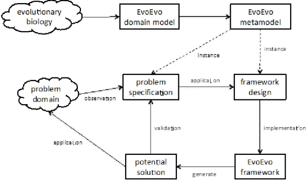
Based on these ideas, Figure 3 captures our approach to engineer an EvoEvo computational framework from the EvoEvo metamodel. The top three boxes represent work reported in D4.1: the domain is evolutionary biology (EvoEvo), the biological domain model was extracted from WP2 and WP3 outputs, which led to the development of the EvoEvo metamodel. The bottom five boxes summarise the engineering components of the EvoEvo computational framework:
Problem domain: the solution to any problem/system to which we apply an algorithm incorporating EvoEvo properties. Like in Figure 2, this does not exist initially, but is the desired output. There is no single engineering domain, one is generated per problem. Problem specification (base CoSMoS analogue: Domain Model): a specification of the
problem to be solved described in EvoEvo terms. Consequently this is an instance of the EvoEvo metamodel as the language we use to describe the problem specification is the language of EvoEvo.
Framework design (base CoSMoS analogue: Platform Model): a design for the EvoEvo framework. It instantiates the relevant concepts in the EvoEvo metamodel, and provides an interface to allow problems to be specified (via a domain model) such that the EvoEvo concepts can be tailored as necessary. It provides the instrumentation that enables the EvoEvo concepts to be recorded and probed.
EvoEvo Framework (base CoSMoS analogue: Simulation platform): this allows us to generate potential algorithm solutions from the implemented EvoEvo properties specified in the platform model.
Potential Solution (base CoSMoS analogue: Results Model): a potential solution to the problem domain (that is, an evolutionary algorithm tailored to the problem) as generated by
the EvoEvo framework. It should fulfil the problem specification (the domain model). This can then be applied to the problem, creating the engineered domain.
Figure 3. CoSMoS approach for developing EvoEvo computational framework.
3. Framework Specification
Given the mapping summarised in Figure 3, this section describes the design (the platform model) of the EvoEvo framework. This is presented mostly by way of UML class diagrams and accompanying descriptive text, with the class diagrams showing the main class concepts involved, along with their relevant attributes and methods.
The purpose of the framework is to enable the creation of bespoke bio-inspired algorithms by providing a user-defined model that augments and specialises the general EvoEvo properties instantiated within the framework. An algorithm may use some, or all, of the concepts described in this section.
First we provide an overview of how the top-level framework generates EvoEvo algorithms, followed by showing how the EvoEvo metamodel is instantiated by the framework. Then we describe the instrumentation concepts within the framework.
3.1. Top-level Framework
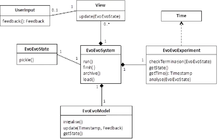
Bespoke EvoEvo algorithms are generated by the EvoEvo computational framework as instances of the EvoEvoSystem class, shown in Figure 4. Figure 5 summarises the main classes involved in creating an instance of EvoEvoSystem, illustrating how an instance of the Configurator class can be used to create an EvoEvoSystem by reading user definitions (see section 4) that are used to parameterise factory class instances in the EvoEvo Framework Library package. This package contains classes that implement the EvoEvo metamodel (section 3.2), the instrumentation classes to view and probe the system (section 3.3), the factory classes to generate instances of these
classes, and various useful utilities (e.g. random number generator). Specifically, we have three factory classes, ModelFactory, ViewFactory and ExperimentFactory, which create the EvoEvoModel, View, and EvoEvoExperiment classes seen in Figure 4.
The EvoEvoSystem class shown in Figure 4 is the main entry point for the generated EvoEvo algorithm, and is composed of an instance of EvoEvoModel (the elements that are part of the domain), an instance of EvoEvoExperiment, and any number of instances of View (the elements added by the platform model). The EvoEvoSystem also has an associated EvoEvoState. These classes are summarised as so:
EvoEvoSystem: controls the running of the algorithm and the communication between its
constituent parts (model, experiment and views). Its main functionality is accessed via the methods:
run(): initialises and runs the algorithm.
finish(): performs clean-up operations once an algorithm run has terminated.
archive(): saves a snapshot of the current state of the algorithm (see EvoEvoState). load(): loads a previously saved snapshot.
EvoEvoModel: an instance of this class instantiate some, or all, of the EvoEvo metamodel (those
parts of the metamodel that we don't require are instantiated as null). It provides a single point of access to the model, controlled from EvoEvoSystem via:
initialise(): initialises the entire model to its starting state.
update(Timestamp, Feedback): provides an update signal containing a Timestamp object (provided by the EvoEvoExperiment), and potentially a Feedback object (provided via UserInput). How the EvoEvoModel uses these inputs is specific its configuration and implementation (see section 3.2 for more details).
getState(): returns the current state of every object in the EvoEvoModel.
EvoEvoExperiment: specifies the experimental setup that will drive the running of EvoEvoModel.
It instantiates the concept of Time from the EvoEvo metamodel to enable this. The main methods provided are:
checkTermination(EvoEvoState): based on the provided EvoEvoState, determines whether the termination condition of the experiment has been met.
getState(): returns the current state of the experiment.
getTime(): Timestamp: return the current Timestamp from the internal model of Time. analyse(EvoEvoState): checks the EvoEvoState to see if it meets a condition for analysis
to take place (e.g. a certain behaviour or structure is observed in the EvoEvoState), then performs the appropriate analysis.
View: provides instrumentation by processing data from the EvoEvoSystem (model and
experiment). Extended to provide visualisations, data logging and statistical probes. User input can be provided via an instance of UserInput.
update(EvoEvoState): updates the view with the current EvoEvoState.
feedback(): Feedback: returns a Feedback object that captures the command inputted by the user.
EvoEvoState: A snapshot of the current state of the whole system.
pickle(): creates a machine or human-readable description of the objects in the EvoEvoState so that they can be archived to, and imported from, text files.
Figure 4. EvoEvoSystem class and its relationships to other top-level classes
3.2. Instantiating the EvoEvo metamodel from the Framework Library
Overview
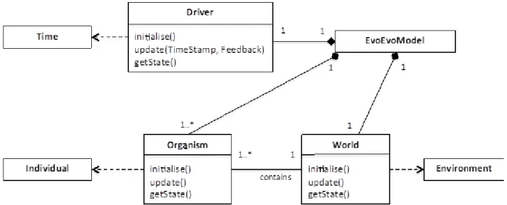
The ModelFactory class creates an EvoEvoModel instance from components in the EvoEvo Framework Library based on the user definition established by the Configurator (Figure 5). The user definition provides configuration options, parameter values and/or code fragments that allow the factory class to build the relevant classes that instantiate concepts from the EvoEvo metamodel. Figure 6 shows the three main classes from which EvoEvoModel is composed: World, Organism and Driver.
Figure 6. Principal classes of EvoEvoModel
World and Organism instantiate Environment and Individual from the metamodel respectively. Driver animates the EvoEvoModel based on update() calls to EvoEvoModel, and therefore
instantiates Time from the metamodel. This time is kept in sync with the wider system based on the Timestamp provided via update() from the EvoEvoExperiment. An example of different Driver behaviours is that we may wish to have a generational based algorithm – such as a standard evolutionary algorithm whereby all individuals update synchronously, then are selected to form the population at the next generation – or a non-generational one where individuals survive for different periods of time, reproducing under a different set of rules. The Driver is responsible for coordinating the update() calls on the Organisms and World. When the World updates it can change providing the mechanism for a changing environment for the Organisms.
Figure 7 shows a design for the Machine class, which forms a base specification for all instantiating machines that follow. Here a Machine has two attributes, state and degradable, and two methods, process() and getState(). getState() returns state and is used to probe the Machine. process() performs the behaviour of the machine, receiving a list of Structure and Energy, and returning a (potentially modified) list of Structures and Energy. The degradable attribute determines whether or not the machine is subject to Entropy machines. If it is not, then this Machine survives for the duration of the EvoEvoSystem (a "physics" machine that determines the rules of the system). Energy can be represented as tokens, which can be stored and used by the Machine
when performing the process() method. If, upon calling process(), the Machine does not possess enough energy tokens, then process() will return its inputs unchanged.
Figure 7. Design for Machine class
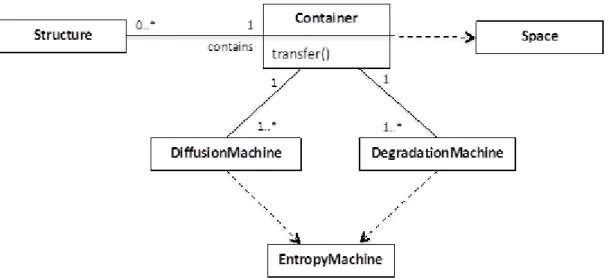
Figure 8 shows the general structure of the Container class. A Container instantiates the Space concept from the metamodel and acts as a location where Structures are stored and potentially interact. The Container is subclassed by elements of the framework design that hold structures such as Machines, Metabolites or other collections of symbols as defined in the metamodel in D4.1. A Container can contain any number of Structures, and has a transfer() method that determines the rules by which Structures are moved between Containers.
Figure 8. The Container class and associated classes
Every Container has at least one DiffusionMachine and at least one DegradationMachine, both of which instantiate the EntropyMachine from the metamodel.
DiffusionMachine defines how Structures "move" within the Container, and by doing so, how
Structures interact. In the simplest case interaction may be stochastic within a “well-mixed” Container whereby Structures are chosen at random to interact. An alternative would be if the Container was implemented as a 2D grid, so the DiffusionMachine would determine how Structures move between grid cells, and only adjacent Structures would interact.
DegradationMachine defines how Structures degrade into their constituent parts. Only Machines
that are degradable are subject to the DegradationMachine. As EntropyMachines, both DiffusionMachine and DegradationMachine are not themselves degradable and remain persistent throughout the lifetime of the instantiated algorithm.
World – Organism Interactions
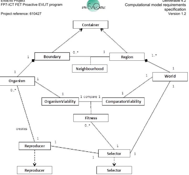
Figure 9 shows the relationships between the Organism and World. As Figure 7 shows, an Organism is located in a World. Extending this, figure 9 shows that a World is composed of a number of different Regions, each of which contain a subset of the total population of Organisms. The way in which the Organism interacts with the other Structures and Organisms in the World is defined by the relationship between an Organism's Boundary and the Region of the World in which it is located. Both Region and Boundary extend Container and potentially implement their own transfer() method, DiffusionMachines and DegradationMachines. The relationship between Boundary and Region provides a Neighbourhood determining the other Organisms and Structures that an Organism can "see" and potentially interact with. It is within the Organism's Boundary that the BoundaryMachines will reside, determining how the transfer() method for the Boundary will function.
Aside from the transfer of Structures between Organisms and Regions, Organisms and the World interact during selection and reproduction of Organisms. An Organism can generate an OrganismViability that describes the state of the properties that determine its current "viability" within the World. What these specific properties are will be entirely dependent on the problem being addressed by the EvoEvo algorithm; an example could be how much resource and energy it has available to reproduce, or the combined set of Metabolites or Metaboliser Machines it can produce that describe the solution to an engineering problem. To determine a Fitness for the Organism, the OrganismViability is compared to the ComparatorViability of the World, which describes how the Fitness can be calculated. The Selector machine of the World uses the Fitness of Organisms to determine which Organisms are subject to the Reproduce machine that will ultimately create new instances of Organism.
Figure 9. Relationship between Organism and World. Reproducer and Selector are instances of
the same concepts in metamodel.
Organism Structure
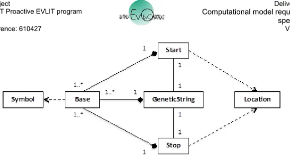
Figure 10 shows the GeneticString, a Structure composed of one or more instances of a Base. A Base is a Symbol from an Alphabet such as {A,T,C,G} or {1,0}. A GeneticString is also associated with two instances of Location, a Start and Stop. Start and Stop are also composed of Bases from the same Alphabet as GeneticString, such as CCG or 10011, and act as identifiers on the GeneticString. For example, Start and Stop are used by the Transcriber machine to locate the section of a GeneticString to be transcribed.
Figure 10. GeneticString with associated Start and Stop Locations.
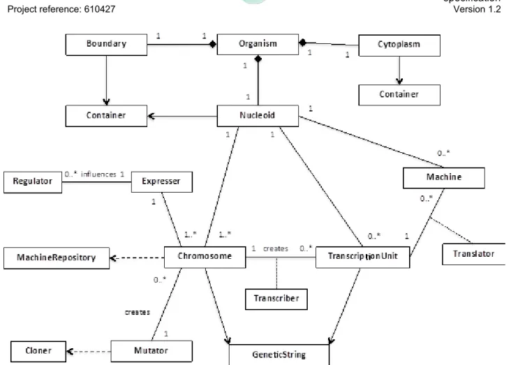
Figure 11 summarises the concepts present within an Organism, which is composed of three classes that extend Container: Boundary, Cytoplasm, Nuceloid.
The Boundary is described in Figure 9, and provides the mechanism to transfer Structures between inside and outside the Organism.
The Cytoplasm provides a space to compute the viability of the Organism (see OrganismViability in Figure 9) via the Metabolites, Metabolism Machines, and Regulatory Machines it contains. The Nucleoid contains the genetic material (Chromosome/s), the Genome Machines, and Regulatory Machines, and is therefore the place where new Machines are created. Each Container is connected (not shown in Figure 11) and movement of Structures between them is definded by their transfer() methods.
The Nucleoid contains one or more Chromosomes that instantiate the metamodel Machine-Repository. Chromosomes are subject to an Expresser that initiates the creation of Transcription-Units via a Transcriber machine. An Expresser can be under the influence of Regulator machines, which increase or decrease the rate at which certain TranscriptionUnits are created. Both Chromosome and TranscriptionUnit inherit from GeneticString. Machines that are encoded on the TranscriptionUnit are created by a Translator machine. New instances of Chromosome can be created by the Mutator (typically during reproduction), which instantiates the Cloner from the metamodel.
Figure 11. Structure of an Organism. Expresser, Transcriber and Translator are instances of the
same concepts in the metamodel. Transfer of Structures can occur between Boundary, Cytoplasm, and Nucleoid (not shown).
3.3. Instantiating Experiment and Views from the Framework Library
Whilst the ModelFactory creates the EvoEvoModel as described above, the ExperimentFactory and ViewFactory create the instrumentation and interfaces to drive, interact and record the EvoEvoModel.
Views fall into three main areas: visualisers, loggers, and statistical probes. All – with the exception of those applying UserInput – are passive and simply receive calls to their update(EvoEvoState) method and process that data accordingly. For visualisers, data is presented to the user for observation; for loggers, data is recorded to a data store (file or database). For statistical probes, state data may be retained to calculate statistics over a period of time and for different objects within the EvoEvoSystem. For Views that incorporate a UserInput (such as a user interface), a Feedback object is passed to the relevant recipient within EvoEvoSystem.
By implementing the master view of Time, an instance of EvoEvoExperiment acts as the experimental control for the EvoEvoSystem, determining the conditions under which it evolves and is monitored. (As previously described, the Driver class in EvoEvoModel implements Time; however the behaviour of this is based on the Timestamp provided by EvoEvoExperiment.) Typically an EvoEvoExperiment instance provides the following:
a termination condition, checked with checkTermination(EvoEvoState), which may be time based (a number of iterations has passed) or based on achieving a certain condition. an up-to-date Timestamp, retrieved with getTime().
master source of random numbers.
analysis conditions that determine the when and how to record and process certain statistics.
numbers of replicate runs, either:
o using the same EvoEvoModel parameters, but different starting conditions
o using different parameter configurations EvoEvo parameters. This functionality may utilise a third party tool such as Spartan [Alden et al, 2013].
4. Applying the Framework
4.1. Overview
Having described the EvoEvo framework design, we now describe how a user can configure the framework to generate an algorithm instance. Figure 5 showed how the Configurator reads files that define how the framework will be instantiated to generate an EvoEvo algorithm. These configuration files, written by the user, contain the necessary information to select, parameterise and specialise components in EvoEvo Framework Library (described in sections 3.2 and 3.3). Specialising components requires providing code fragments, typically methods of one of the classes described above. The format of the configuration files will be implementation specific. The selection of components from the framework and their parameterisation could be described in plain text files or formatted using XML. How components are specialised with code fragments will be based on the language and technologies employed by the framework's implementation (to be provided in D4.3).
In essence, the framework enables the user to set the initial conditions of the algorithm, then allows the EvoEvo processes to evolve better problem-solving machines, and potentially better evolutionary machines. There are two main areas that the user needs to define: the EvoEvo model properties they require (summarised in section 3.2), and the supporting instrumentation (section 3.3). Not every part of the framework needs to be functional. For example, if the user does not wish to have RegulationMachines, these are simply instantiated as null and form no part in the EvoEvo-Model dynamics.
Configuration of the supporting instrumentation is covered in section 4.5. First we consider the necessary user configuration of the EvoEvoModel summarised in Figure 6. The EvoEvoModel class is configured simply by configuring its containing classes, and Organism and World are described in the sections below. The Time model implemented by Driver is configured by choosing a pre-defined default from the framework, such as generational updates (all Organisms and World updated once per TimeStamp). In many of the cases we describe below default options are available for configuration. These are simply used to select between different pre-existing code in the framework.
4.2. Specifying Machines
The majority of the behaviours in an EvoEvoModel are carried out by Machines. These Machines may be fixed within the system or able to change and evolve, and the engineering problem will dictate which machines are defined to be fixed and which are able to evolve. There are two aspects to whether a Machine can change within an EvoEvoModel. First is whether instances of Machine persist; second is whether the behaviour of new instances of a Machine can change. Based on these we have two categories of Machine:
Fixed/“Physics” Machines implement the physical properties of the system. They are created during initialise() of EvoEvoModel and persist for the duration of the EvoEvoModel. These Machines have their degradable property set to False, and so they are not destroyed by DegradationMachines.
Evolvable/“Biological” Machines are encoded on the Chromosomes, so instances are created whenever their MachineTemplate is expressed as part of the TranscriptionUnit. As the details on how to create these Machine instances are on the Chromosome, they are potentially able to change when mutated (via Mutator machines). Their degradable attribute is set to True, making them available to the DegradationMachines.
All Machines, whether fixed or evolvable, follow the structure in Figure 7, and require a process() method and MachineState attribute to be defined. For fixed Machines, these can be chosen from framework defaults or supplied as code fragments by the user. For evolvable Machines whatever is on the Chromosome for a MachineTemplate is used to define its MachineState attribute, and the behaviour of the process() method. In order to define this, the process() method of a Translator needs the necessary translation between the Alphabet Symbols on the MachineTemplate and the Machine's encoding.
4.3. Specifying the Problem
There are two driving factors to how the user will configure the required EvoEvo properties: the engineering problem (see Figure 3), and the desired EvoEvo properties to tackle that problem. Here we demonstrate how the problem specification from Figure 3 is applied to the general EvoEvo concepts inherent in the framework. There are two parts of the EvoEvoModel that encode the engineering problem: the viability comparison (Figure 9), and the action of the Organism's Metabolism Machines in the Cytoplasm that define the Organisms's Viability. The user must specify the following via computer code:
OrganismViability: some property of the Individuals’ Cytoplasm (the MetaboliteMachines, Metabolites, energy tokens)
ComparatorViability: statement of an “ideal” property of an Individual in the same terms as that which describes the OrganismViability. The ComparatorViability might change over time to give a dynamic environment/engineering problem. It might also be linked to user feedback.
The OrganismViability and ComparatorViability must be comparable to generate a Fitness. For example, the OrganismViability might be how much resource and energy it has stored, which is then compared to a ComparatorViability that defines a threshold for reproduction. Alternatively, the OrganismViability might be described in terms of the set of Metabolites or MetaboliteMachines it
can produce, which describe the solution to an engineering problem. A generated Fitness from the viability comparison is used by the Selector.
4.4. Specifying the Organism and World
Both the Organism and World use Containers via the Region in World, and Boundary, Nucleoid and Cytoplasm in Organism. As these extend Container, they require their transfer() methods to be defined along with their DiffusionMachine and DegradationMachine (for which defaults will be provided in the framework). Containers also need to have a topology defined that determines the location of Structures contained within the Container (and allows Neighbourhood instances to be calculated in the case of Region). Default choices include unordered list (“well mixed”) and 2D space. The user may specify their own topology. Examples of defaults for transfer() of a Container include: rate of transfer of structures, and only certain machine types can transfer between Containers. The behaviour of DiffusionMachines will depends on the topology chosen for the container.
The behaviours of an Organism are specified by its component parts outlined in Figures 9 and 11. An Organism must have a Cytoplasm for Metabolisers, a Nucleoid for the Chromosomes and Genome Machines, and a Boundary for the BoundaryMachines. The simplest Boundary is one in which nothing is transferred or one that is flooded with unbounded Energy and Metabolites. Regulation is optional and selected by the user. If enabled, the Regulators can generate a Regulation Network for the Genome.
The user must also select and configure the following: The number of Organisms to create on initialise() Any bounds on the number of Organisms that can exist Number of Chromosomes per Organism
For each chromosome: o Base Alphabet
o Initial number of bases
o Which machine types are encoded (the Metabolisers, Genome Machines, Boundary Machines, Regulators) so that the correct Transcribers and Translators are used o Start and Stop locations
o Shape (circular, linear, double-stranded)
o Mutators (can be based on framework defaults) o Expresser (can be based on framework defaults)
o Transcribers that contain the mapping between alphabets Chromosome and TranscriptionUnit alphabets
For TranscriptionUnits:
o Initial number of bases o Start and Stop locations
Code will need to be provided for the process() of each Translator. This will encode the rules for the Metabolisers that will be created from MachineTemplates extracted from the Chromosome.
Selector (can be based on framework defaults)
Reproducer (can be based on framework defaults that manage how to split contents of an Organism)
4.5. Specifying the Instrumentation
The user may specify any number of Views to receive EvoEvoState updates, which can either be selected from the framework or provided as code. The framework will provide Views that log data, display data and perform statistical analyses.
The EvoEvoExperiment requires the user to select, or provide, a timing model, which will drive both the EvoEvoModel and the coordination with Views. Two default timing models are generational (all components update once per tick) and non-generational (components update at random or when they have the capacity to do so). The EvoEvoExperiment also requires the specification of a termination condition (such as a certain time point has been reached), the starting conditions for replicate runs (see section 3.3), and conditions under which to certain analyses are to take place (performed by a View).
5. Next Steps
Deliverable D4.1 defines the basic Machine metamodel, and an enrichment of it, the EvoEvo metamodel, and shows how the biological models of EvoEvo can be expressed as biological instances of the metamodel. This deliverable D4.2 defines a computational instantiation of that EvoEvo metamodel, suitable for using as a framework for EvoEvo-style evolutionary algorithms. The next steps are:
to implement such an evolutionary framework (D4.3) to apply the framework to suitable applications (WP5)
The framework is necessarily complicated, given its genesis in biological processes, and its application to hard dynamic problems. Because of this, implementation will proceed via a short series of prototype implementations applied to toy applications, to validate and update the framework design as necessary, before full deployment in WP5.
6. References
[Alden et al., 2013] Alden K, Read M, Timmis J, Andrews PS, Veiga-Fernandes H, et al. (2013) Correction: Spartan: A Comprehensive Tool for Understanding Uncertainty in Simulations of Biological Systems. PLoS Comput Biol 9(8).
[Andrews et al., 2011] P. S. Andrews, S. Stepney, T. Hoverd, F. A. C. Polack, A. T. Sampson, J. Timmis, 2011, CoSMoS process, models, and metamodels. CoSMoS workshop, Paris,
![Figure 2. Relationship between metamodel and engineered domain (reproduced from [Andrews et al., 2011])](https://thumb-eu.123doks.com/thumbv2/123doknet/12768044.360217/6.892.130.761.61.541/figure-relationship-metamodel-engineered-domain-reproduced-andrews-et.webp)