Publisher’s version / Version de l'éditeur:
Pure and Applied Chemistry, 88, 5, 2016-06-20
READ THESE TERMS AND CONDITIONS CAREFULLY BEFORE USING THIS WEBSITE. https://nrc-publications.canada.ca/eng/copyright
Vous avez des questions? Nous pouvons vous aider. Pour communiquer directement avec un auteur, consultez la première page de la revue dans laquelle son article a été publié afin de trouver ses coordonnées. Si vous n’arrivez pas à les repérer, communiquez avec nous à PublicationsArchive-ArchivesPublications@nrc-cnrc.gc.ca.
Questions? Contact the NRC Publications Archive team at
PublicationsArchive-ArchivesPublications@nrc-cnrc.gc.ca. If you wish to email the authors directly, please see the first page of the publication for their contact information.
Archives des publications du CNRC
This publication could be one of several versions: author’s original, accepted manuscript or the publisher’s version. / La version de cette publication peut être l’une des suivantes : la version prépublication de l’auteur, la version acceptée du manuscrit ou la version de l’éditeur.
For the publisher’s version, please access the DOI link below./ Pour consulter la version de l’éditeur, utilisez le lien DOI ci-dessous.
https://doi.org/10.1515/pac-2015-0903
Access and use of this website and the material on it are subject to the Terms and Conditions set forth at
Glossary of terms used in extraction (IUPAC Recommendations 2016)
Poole, Colin; Mester, Zoltan; Miró, Manuel; Pedersen-bjergaard, Stig;
Pawliszyn, Janusz
https://publications-cnrc.canada.ca/fra/droits
L’accès à ce site Web et l’utilisation de son contenu sont assujettis aux conditions présentées dans le site LISEZ CES CONDITIONS ATTENTIVEMENT AVANT D’UTILISER CE SITE WEB.
NRC Publications Record / Notice d'Archives des publications de CNRC:
https://nrc-publications.canada.ca/eng/view/object/?id=18870f36-9aa4-4fab-bce5-1a2116a892b9 https://publications-cnrc.canada.ca/fra/voir/objet/?id=18870f36-9aa4-4fab-bce5-1a2116a892b9IUPAC Recommendations
Colin Poole, Zoltan Mester, Manuel Miró, Stig Pedersen-Bjergaard
and Janusz Pawliszyn*
Glossary of terms used in extraction
(IUPAC Recommendations 2016)
DOI 10.1515/pac-2015-0903
Received September 16, 2015; accepted March 27, 2016
Abstract: Approaches for analytical-scale extraction are developing rapidly as new strategies are
imple-mented to improve sample throughput, to minimize material use in laboratory methods, and to develop on-site capabilities. In this contribution, definitions and recommendations for symbols for the terms used in analytical extraction are presented. Exhaustive, microextraction, elevated temperature, microwave- and ultrasound-assisted, parallel batch, flow through systems, and membrane extraction approaches are dis-cussed. An associated tutorial titled “Extraction” provides a detailed introduction to the topic.
Keywords: extraction; recommendations; terminology.
CONTENTS
1. INTRODUCTION ...517
2. ALPHABETICAL ENTRIES ... 518
MEMBERSHIP OF SPONSORING BODY ... 556
REFERENCES ... 556
1 Introduction
The general procedure for the analysis of complex samples typically consists of several steps identified as sam-pling, sample preparation, separation, quantification, statistical evaluation, and decision-making. Each step is critical to obtain informative results for optimum decision making. In many cases, the key is the selection of the most appropriate sample preparation step for a particular task. The objective of this step is to isolate target analytes from a matrix, because most analytical instruments are designed to handle the analytes but are fre-quently incapable of accommodating the analytes and matrix together. Sample preparation usually involves
extraction procedures and can also include “clean-up” procedures for very complex, “dirty” samples. This step
must also concentrate the analytes to a level suitable for detection, and therefore, sample preparation methods typically include enrichment. The fundamental basis for extraction processes is often substantially different to those employed in chromatographic separations or other traditional disciplines of analytical chemistry. Analytical-scale extractions generally resemble the corresponding engineering processes, but on a smaller
*Corresponding author: Janusz Pawliszyn, Department of Chemistry, University of Waterloo, Waterloo, ON N2L 3G1, Canada,
e-mail: janusz@uwaterloo.ca
Colin Poole: Department of Chemistry, Wayne State University, Detroit, MI 48202, USA
Zoltan Mester: National Research Council of Canada, 1200 Montreal Road, Ottawa, Ontario K1A 0R6, Canada
Manuel Miró: FI-TRACE group, Department of Chemistry, University of the Balearic Islands, Carretera de Valldemossa km 7.5,
E-07122 Palma de Mallorca, Spain
scale. There is a tendency to name the extraction techniques according to random criteria. The objective of this contribution is to develop a consistent nomenclature for terms to be used to describe the extraction processes. An associated tutorial, titled “Extraction,” provides a detailed overview of the extraction processes.
If a reference is given to a PAC Recommendation without qualification, then the term and definition are unchanged from the earlier version. If the reference reads “Adapted from Reference [xx],” then some changes have been made. Terms from the JCGM VIM [1] are cross referenced without repeating the definition. A qualifying term in parentheses after a term is used to restrict the scope for a term with use in other fields of chemistry or science.
2 Alphabetical entries
2.1 General terms (Fundamental processes)
2.1.1 absorption (extraction)Process leading to extraction where analytes are partitioned from their matrix into a liquid
Note: The use of term absorption here should be distinguished from the use of absorption in spectroscopy for the phenomenon in which radiation transfers some or all of its energy to matter.
Adapted from reference: [2].
2.1.2 adsorbent
A condensed phase at the surface of which adsorption may occur. Reference: [2].
2.1.3 adsorption
Increase in the concentration of a dissolved substance at the interface of a condensed phase due to the opera-tion of surface forces. Adsorpopera-tion can also occur at the interface of a condensed and a gaseous phase. Reference: [2].
2.1.4 analyte
Part of a system embodying the measurand (VIM 2.3 [1]). Adapted from reference: [3].
2.1.5 boundary layer or diffusion layer (extraction)
Concentration boundary layer
Region in the vicinity of the interface between the sample and extraction phase where mass transfer is deter-mined by diffusion.
2.1.6 boundary layer thickness
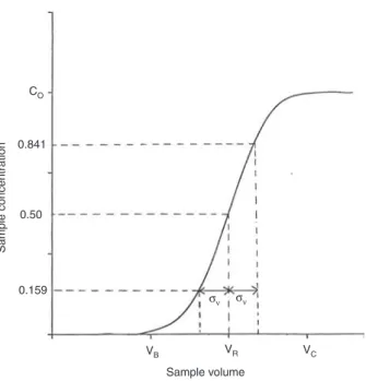
2.1.7 breakthrough volume
The volume at which a defined amount of an analyte pumped continuously through an extraction device will begin to be eluted.
Note 1: The breakthrough volume, VB, for a particular compound and sampling device is determined by its breakthrough curve, Fig. 1 [3].
Note 2: Defined amounts are usually given as a percentage vol/vol of the sample volume (e.g. 1 %, 5 % or 10 %, etc.).
Reference: [3].
2.1.8 distribution
Apportionment of a solute between two phases.
Note 1: The term partition or extraction may also be used in this sense where appropriate. Reference: [4].
2.1.9 distribution ratio, D
Ratio of the total concentration of an analyte in the extraction phase, regardless of its chemical form, to its total concentration in the other phase.
Note: D is dependent on experimental conditions (pH, presence of complexing agents, etc.) and does not
necessarily imply that equilibrium has been achieved. Adapted from reference: [4].
VB VR σν σν VC Sample volume CO 0.841 0.50 0.159 Sample concentration
Fig. 1: Typical breakthrough curve indicating the breakthrough volume VB and the sample volume corresponding to the satura-tion capacity of the sorbent VC (VR corresponds to the chromatographic elution volume and σV the standard deviation of the derivative of the curve).
2.1.10 distribution constant, KD
partition ratio
distribution coefficient, distribution ratio, partition constant, and extraction constant should not be used Ratio of the concentration of an analyte in a single defined form, A, in phase 1 to its concentration in the same form in a second phase (phase 2) at equilibrium.
D [A] /[A]1 2
K =
Note 1: If the equation relates to an organic-aqueous biphasic system, the organic phase concentration is by convention the numerator and the aqueous phase concentration the denominator.
Note 2: In the case of non-ideal mixtures, concentrations should be replaced by activities. The distribution constant is invariant only if the activity coefficients are constant, which is not true in concentrated solutions.
Note 3: The use of the inverse ratio (aqueous/organic) may be appropriate in certain cases, e.g. where the organic phase forms the feed, but its use in such cases should be clearly specified. The ratio of the concentration in the denser phase to the less dense phase is not recommended, as it can be ambiguous.
2.1.11 ion-pair extraction
Transfer of ions from an aqueous phase to an immiscible liquid (or solid) phase by adding an ion of comple-mentary charge to the aqueous phase.
2.1.12 partition
This term is often used as a synonym for distribution and extraction. However, an essential difference exists by definition between distribution constant (partition ratio) and partition constant.
Note: This term should be, but is not invariably, applied to the distribution of a single definite chemical species between the two phases.
2.1.13 partition constant, o
KD
partition coefficient should not be used
Ratio of the activity of a species A in the extract aA,1 to the activity in a second phase with which it is in equi-librium aA,2.
=
D(A) A,1 A,2
K a a
Note: The value of KD depends on the choice of standard states and on the temperature (and since liquids
are weakly compressible, on pressure at high pressures). Reference: [4].
2.1.14 phase ratio
Ratio of the extraction phase and sample solution contained in the extraction device.
Note 1: Ratio of the volume of extraction phase to the volume of sample solution in liquid–liquid extraction. Note 2: Ratio of the headspace volume to the condensed phase volume in a closed container for headspace
Note 3: Ratio of the surface area of the extraction phase to the volume of sample solution contained in the extraction device for solid-phase extraction.
Note 4: When the extraction phase is a gas or liquid, the sum of the extraction phase and sample solution volumes equals the volume of the extraction device.
2.1.15 solvent (extraction)
Immiscible fluid added to a process for the purpose of extracting material from the sample.
2.1.16 sorbent
Condensed phase where extraction of analytes can occur at the surface and in the bulk.
Note 1: If extraction occurs exclusively at the surface then adsorbent is the preferred term and if exclusively in the bulk then absorbent should be used.
Note 2: Sorbent is typically used explicitly to describe a condensed phase where extraction occurs simulta-neously by adsorption and absorption, or where the true mechanism has not been established and the use of adsorbent or absorbent would be inappropriate.
2.2 General terms (Process technology)
2.2.1 acceptor phaseComponent of a multi-phase system into which the target analytes are extracted. Note 1: When the acceptor phase is a liquid the term acceptor solution may be used.
Note 2: In extractions employing a semipermeable membrane for phase separation the acceptor phase is the phase to which analytes are transferred from the donor phase.
2.2.2 active sampling
Continuous extraction with movement of the sample matrix with respect to the extraction phase.
2.2.3 batch extraction
Extraction in which the extraction phase and the sample are confined in an extraction vessel and processed
according to a defined procedure.
Note 1: Term “batch” is also used in extraction to indicate a number of samples extracted sequentially or simultaneously by the same procedure (e.g. extraction of sample batch(es)).
2.2.4 calibrant in extraction phase
Internal standard that is incorporated in the extraction phase for calibration [VIM 2.39 [1].
2.2.5 charcoal tube
Tube filled with charcoal typically used to adsorb analytes from the gas or liquid phase.
Note: Activated charcoal was used in early applications but a wider selection of carbon materials are cur-rently used, with properties tailored to each application
2.2.6 continuous extraction
Extraction in which the sample is continuously introduced into the extraction device.
2.2.7 countercurrent extraction
Extraction in which both phases are continuously added (or changed) and flow (or move) in opposite
direc-tions as the extraction progresses.
Note 1: The phases are either immiscible or separated by a membrane.
2.2.8 distribution constant calibration
Calibration (VIM 2.39 [1]) for extraction when close to equilibrium conditions, using a known distribution constant for the analyte.
2.2.9 donor phase
In extraction, the sample or sample solution.
2.2.10 dynamic extraction
Extraction in which clean (or recycled) extraction phase is continuously passed through the sample.
Note: The extraction phase can be a gas or a liquid.
2.2.11 enrichment factor (S)
The factor by which the ratio of two substances in the feed must be multiplied to give their ratio after treatment. QA/QB = SAB(Q′A/Q′B) where QA and Q′A are the final and initial amounts of species A and QB and Q′B are the final
and initial amount of species B. Hence, SAB = EA/EB where E is the fraction extracted.
Reference: [4].
2.2.12 equilibration
Operation by which a system of two or more phases is brought to a condition where further changes with time do not occur.
Note: This term is not synonymous with pre-equilibrium and should not be used in that sense. Reference: [4].
2.2.13 exhaustive extraction
Type of extraction where the intent is a complete extraction of the analytes.
2.2.14 external calibration
Calibration (VIM 2.39 [1]) employing a simplified sample matrix spiked with target analyte embodying a
2.2.15 extract (noun)
Separated phase that contains material isolated from another phase. Adapted from reference: [4].
2.2.16 extractant
Synonym: extracting agent
The active component(s) primarily responsible for transfer of a solute from one phase to the other. Reference: [4].
2.2.17 extraction
Transfer of analytes from one phase to a different phase where further processing and analysis occurs. Adapted from reference: [4].
2.2.18 extraction phase
Liquid, solid, or gas phase in contact with the sample for the purpose of removal of analytes from the sample
matrix.
2.2.19 extraction rate
kinetics of extraction
Rate at which analytes are transferred from the sample to the extraction phase.
2.2.20 extraction recovery
See fraction extracted.
2.2.21 feed
Solution or gas containing analyte introduced into an extraction.
Note: If feed is used without qualification, the term may be taken to designate the initial liquid phase con-taining the main solute to be transferred or sample solution in a batch process.
Adapted from reference: [4].
2.2.22 fluorous extraction
Extraction in a biphasic system in which the main component of one phase is a highly fluorinated solvent
(liquid–liquid extraction) or highly fluorinated sorbent (solid-phase extraction). Reference: [5].
2.2.23 fraction extracted (E)
Extraction recovery
Ratio of the amount of analyte extracted under specified conditions to the amount of analyte in the sample. EA = QA/Q′A where QA is the mass of A extracted and Q′A is the total mass of A present at the start.
Note 1: Fraction extracted is typically expressed as a percentage with units of mol/mol, or g/g. Adapted from reference: [4].
2.2.24 fractionation (of analytes)
Extraction of an analyte, or a group of analytes, from a sample according to physical (e.g. size, solubility) or
chemical (e.g. bonding, reactivity) properties. Adapted from reference: [6].
2.2.25 leaching
Dissolution of sample components from a solid with a liquid in which the solid phase is not wholly soluble. Adapted from reference: [4].
2.2.26 mass transfer
Spontaneous (irreversible) process of transfer of mass across non-homogeneous fields. The driving force can be the difference in concentration (in liquids) or partial pressure (in gases) of the component. In fluids, mass transfer may be enhanced by turbulent flow. In biological systems, mass transfer through membranes may result from normal diffusion, facilitated diffusion, or active transport
Reference: [7].
2.2.27 matrix
The components of the sample other than the analyte(s). Reference: [8].
2.2.28 matrix-matched calibration
Calibration (VIM 2.39 [1]) employing external calibration in which standard solutions of target analytes are
prepared in a solution of analyte-free matrix.
Note: Matrix-matched calibration is used to minimize the matrix effect on the measurement of target
meas-urands (VIM 2.3 [1]) [9, 10].
References: [9, 10].
2.2.29 microextraction (methodological approach)
Extraction method characterized by a low phase ratio, so that at equilibrium the fraction extracted is low (not
exhaustive). Reference: [11].
2.2.30 microextraction (technique)
Extraction technique in which the extraction phase (liquid or solid) is substantially smaller than the sample
volume.
Note: The amount of extraction phase is typically < 100 µl or < 10 mg and the sample volume > 1 ml.
2.2.31 multiwell sample plate
Plate with multiple wells for individual samples.
2.2.32 optimisation of extraction
Adjustment of extraction parameters to achieve a defined goal.
Note: Many extractions are controlled by several parameters and their interactions. Optimum conditions are more efficiently identified by multivariate methods.
Related terms: design of experiments, optimization.
2.2.33 passive sampling
Extraction process driven by diffusion of analytes towards the extraction phase.
2.2.34 preconcentration (extraction)
An operation (process) by which the analyte(s) and/or sample concentration is increased prior to extraction. Adapted from reference: [12].
2.2.35 Raffinate
Phase left from the feed after being contacted by the extracting phase. Adapted from reference: [4].
2.2.36 salting in
Addition of an electrolyte to an aqueous phase to decrease the distribution ratio of the analyte(s) or matrix. Related term: salting out.
2.2.37 salting out
Addition of an electrolyte to an aqueous phase to increase the distribution ratio of the analyte(s).
Note: The term is also used for the addition of electrolytes to reduce the mutual partial miscibility of two liquids.
Related term: salting in. Adapted from reference: [4].
2.2.38 saturation capacity
Sample volume at which the concentration of analyte at the exit of a sampling device is the same as the sample concentration.
Note 1: Corresponds to VC in Fig. 1.
Note 2: Corresponds to the sample volume (or sample amount) that results in the isolation of the maximum amount of analyte, but with a lower overall recovery because a fraction of the sample is lost.
2.2.39 sequential extraction
Extraction wherein extractants of increasing strength or different chemical character are used in order to
extract analytes of interest.
Note: The most commonly used approaches in elemental analysis are the BCR [13] (now termed Standards, Measurement and Testing Program) and Tessier [14] procedures.
References: [13, 14].
2.2.40 speciation analysis
Analytical activities identifying and/or measuring the quantities of one or more individual chemical species in a sample.
Reference: [6].
2.2.41 static extraction
Batch extraction in which the extraction phase attains a constant composition before phase separation.
Note 1: If the analytes are initially present as a solution in an immiscible liquid phase the process is synony-mous with liquid–liquid extraction.
Note 2: If the sample is a solid that is partially soluble in the extraction phase then leaching may be a more appropriate term.
Related term: static headspace analysis.
2.2.42 steady state extraction
The state of a continuous process operating in such a way that the concentration of solutes in exit streams remains constant with respect to time for constant feed concentrations, even though the two phases are not necessarily in thermodynamic equilibrium in any part of the process. The term equilibrium should not be used to describe this situation.
Reference: [4].
2.2.43 time-weighted average sampling
TWA sampling
A passive or active sampling strategy over a relatively long time, during which the amount of analyte(s) extracted is proportional to its average (mean) concentration over that time.
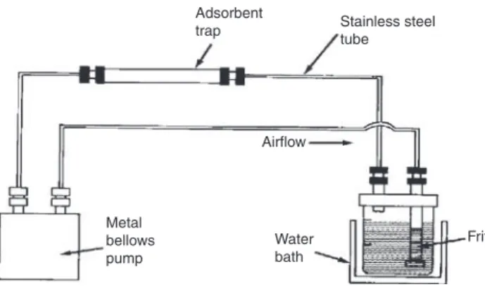
Adsorbent
trap Stainless steel
tube Frit Airflow Water bath Metal bellows pump
Fig. 2: Typical apparatus for closed-loop stripping analysis.
3 Extraction techniques
3.1 Gas-phase extraction
3.1.1 chemical hydride generation, (CHG)
Type of chemical vapor generation wherein volatile hydrides are generated by reaction with (usually) borane complexes in aqueous solution.
Reference: [15].
3.1.2 chemical vapour generation, (CVG)
Extraction of analyte from a sample by a chemical reaction-generating gaseous species.
Note: The analyte is usually an element.
3.1.3 closed-loop extraction
Closed-loop stripping analysis
Extraction by a fixed volume of gas continuously recycled through the sample and a sorbent trap by a pump
in a closed-circuit arrangement.
Note 1: A typical apparatus is shown in Fig. 2 [16, 17].
Note 2: Closed-loop extraction was developed for trace analysis of volatile compounds (at mass concentra-tions of ng L–1) in drinking water.
References: [16, 17].
3.1.4 cryogenic trap
Device used to concentrate volatile analytes from the gas phase by condensation on a cold surface.
Note: Typically, cryogenic traps have a low thermal mass to respond rapidly to changes in temperature and are prepared from short lengths of capillary tubing. Sub-ambient temperatures are required for the efficient collection of analytes from a flowing gas stream and above ambient temperatures for evaporation into a flowing gas stream for analysis, usually by gas chromatography or atomic
Fig. 3: Typical apparatus for analysis by dynamic headspace (purge and trap). The gas flow (sparging gas) enters at the bottom
of the sample container transporting volatile compounds through the headspace and purge head to the desorption tube for collection.
3.1.5 denuder (device)
Apparatus for the extraction of volatile analytes from a flowing gas stream by diffusion to the wall of a collec-tion vessel, where they are retained by chemisorpcollec-tion or strong physisorpcollec-tion by the wall coating.
Note 1: There are many design variations [18].
Note 2: Both liquid and solid sorbents are used for trapping. Reference: [18].
3.1.6 dynamic headspace analysis
Continuous removal of headspace above a sample by a flow of inert gas over or through the sample until all or a significant portion of the analytes have been removed from the sample. Sample vapors are typically transferred to a sorbent trap or cryogenic trap for collection.
Note 1: Purge-and-trap is a version of dynamic headspace analysis in which volatile compounds are purged from solution by a continuous stream of gas bubbles (sparging gas) and transported through the headspace to a sorbent or cryogenic trap for collection.
Note 2: A typical apparatus for purge-and-trap is shown in Fig. 3.
3.1.7 extractive distillation
Separation of close-boiling liquids by fractional distillation in the presence of a low-volatility solvent or salt that selectively interacts with one or more components of the mixture, increasing the difference in vapor
pressure of the sample components.
Note 1: If the separation solvent forms an azeotrope with one or more sample components the process is called azeotropic distillation,
3.1.8 flash desorption
Thermal desorption where the temperature of a packed tube or cryogenic trap is rapidly increased to transfer
condensed or sorbed compounds to the gas phase.
3.1.9 foam fractionation
Extraction method for the isolation of surface active compounds by their preferential adsorption at a gas-liquid (bubble) interface formed by passage of an inert gas through (typically) an aqueous solution.
3.1.10 Full evaporation headspace analysis
Small volume of sample in a headspace vessel maintained at a temperature sufficient to cause complete evaporation of analytes
Note 1: The full evaporation technique is used with both static and dynamic headspace analysis.
Note 2: Equilibrium between the condensed and vapor phases no longer exists. As a consequence, the pos-sibility of matrix interferences is reduced and the fraction extracted for low-volatility compounds is increased.
3.1.11 headspace
The volume of gas phase above a sample in a closed container.
3.1.12 impinger (extraction)
see also impinger for particle collection
Simple glass bubbling chamber for vacuum-sampling of volatile analytes by passage through an extraction solution, the purpose of which is to capture and concentrate target analytes.
Note: Isolation by reaction with the extraction solution is common. Selectivity depends on the chemical specificity of the extraction solution.
3.1.13 multiple headspace extraction
Dynamic gas extraction carried out stepwise, with sequential analysis of a number of headspace samples taken from the same vial.
Note 1: At equilibrium the headspace is sampled and the remainder (or most of it) is exhausted and replaced by fresh gas phase. The process is repeated and the original sample concentration estimated from the peak areas for two consecutive extractions.
2 1 T 1 2 A A A A = −
where AT = estimated sum of all partial peak areas corresponding to exhaustive extraction, A1 the
peak area obtained from the first headspace fraction, and A2 the peak area obtained in the second (consecutive) headspace fraction.
D C E A G F H B
Fig. 4: Apparatus for simultaneous steam distillation-solvent extraction with a lighter-than-water extraction phase. A = aqueous
sample solution or slurry; B = immiscible organic solvent and receiving flask for extracted compounds; C = bowl for phase separation; D, E, F, and G are solvent or vapour transfer arms; and H = entry port for additional solvent or alternative sample introduction position for continuous liquid–liquid extraction. Switching the position of flasks A and B allows extraction with a heavier-than-water extraction solvent.
3.1.14 simultaneous steam distillation-solvent extraction
A sample dispersed in water and a water immiscible organic solvent (extraction phase) in separate flasks are heated simultaneously and their vapours co-condensed and separated into two streams in which water is returned to the sample flask and the extraction phase to the organic solvent flask.
Note: A typical apparatus for simultaneous steam distillation-solvent extraction with a lighter-than-water extraction solvent is shown in Fig. 4 [18].
Reference: [19].
3.1.15 sorbent trap
Tube filled with porous sorbent typically used to extract analytes from the gas phase.
Note: The performance of a sorbent tube depends on the sorbent type, temperature, gas flow rate, and desorption time.
3.1.16 static headspace analysis
Method of analysis, in which a small aliquot of the gas phase in contact with the sample in a closed container is withdrawn for analysis.
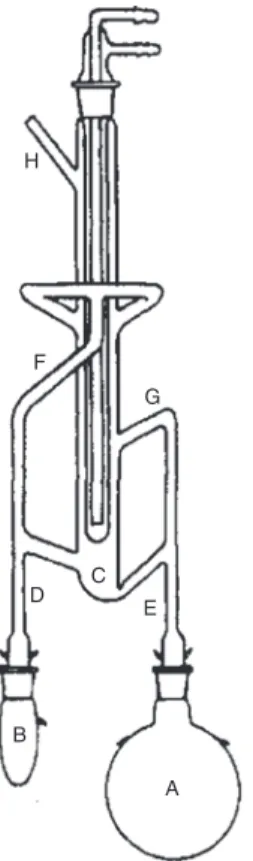
Organic phase Aqueous phase Bubble 1 4 3 2
Fig. 5: Typical apparatus for extraction based on sublation. Identification: (1) nitrogen gas supply; (2) rotameter; (3) floatation
cell; and (4) sintered glass disc [5].
Note 1: At equilibrium, the analyte concentration in the gas phase is related to the sample concentration by a partition constant.
Note 2: The sample vessel is thermostatted.
3.1.17 sublation
Flotation process in which one or more analytes are adsorbed on the surface of gas bubbles moving through a solution and collected in an upper layer of immiscible solvent, or in a sorbent trap.
Note 1: A typical apparatus for sublation is shown in Fig. 5 [20].
Note 2: As there is no liquid-phase mixing in the bulk of the system, recoveries can approach 100 %. Adapted from references: [4, 20].
3.1.18 thermal desorption
See flash desorption.
3.1.19 thermal extraction
Release of volatile compounds from a sample by heat.
Note: The volatile compounds are typically transported by a gas stream to a sorbent tube or cryogenic trap for collection.
3.1.20 thin-layer headspace analysis (TLHS)
Dynamic headspace extraction of analytes from a flowing sample solution in the form of a thin film on the surface of a heated tube.
Note: Volatile compounds in the sample solution pass into the gas phase and are continuously swept out of the tube for analysis or detection.
3.2 Liquid-liquid extraction
3.2.1 back extractionstripping
Process of removing analytes from an extract by their distribution to a different phase.
Note: As normally used, back extraction refers to the main compounds present or target analytes. It is an operation commonly employed in liquid-liquid extraction to enhance selectivity or to improve the compatibility of the extract with separation and measurement techniques.
Adapted from reference: [4].
3.2.2 biphasic system (liquid-liquid extraction)
Equilibrium system containing two or more solvents forming two phases with a single interface.
3.2.3 chelation solvent extraction
Extraction method wherein charged analytes are extracted from an aqueous phase into an organic phase,
assisted by a chelating agent.
Note 1: The chelating agent replaces water molecules in the coordination sphere of the metal ions. Conse-quently, the resultant metal chelates have a hydrophobic character which facilitates their transfer to the organic phase [21].
Note 2: The analyte(s) are usually metal ions. Reference: [21].
3.2.4 cloud point extraction
Coacervative extraction at a temperature above the cloud point temperature.
3.2.5 coacervative extraction
Extraction by a surfactant-rich, water-immiscible phase formed by adding a dehydrating agent to a colloidal
solution of the sample and a surfactant above its critical micelle concentration.
Note 1: In cloud point extraction a small volume “surfactant-rich” phase enriched in sample components of moderate water solubility and a bulk aqueous phase with dissolved surfactant and highly water soluble compounds are formed [22].
Reference: [22].
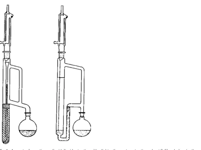
3.2.6 continuous liquid–liquid extraction
Extraction in which a water–immiscible extraction solvent is continuously percolated through an aqueous
solution and returned to the extraction solvent reservoir.
Note 1: Typically, a fixed volume of extraction solvent is recycled through the aqueous sample solution by distillation and condensation, and dripped into the sample solution. A siphon mechanism allows continuous recovery of the extraction solvent based on its relative density.
Fig. 6: Apparatus for continuous liquid–liquid extraction with a lighter-than-water extraction solvent (left) and a
heavier-than-water extraction solvent (right). In each case the extraction solvent is contained in the round bottom flask and the aqueous sample in the vertical glass column.
Note 3: Continuous liquid-liquid extraction techniques are used when the sample volume is large, the distri-bution constant is small, or the rate of extraction is slow.
3.2.7 countercurrent chromatography (CCC)
Type of liquid–liquid chromatography using a support-free liquid stationary phase held in place by centrifu-gal forces while the other phase (the mobile phase) moves through it in a definite direction.
Note 1: CCC is a continuous dynamic process under steady state conditions in which equilibrium may occur but is not essential [23–25].
Note 2: CCC differs from countercurrent distribution (CCD) in that CCD is a discontinuous process based on the attainment of equilibrium prior to phase transfer in a multi-stage apparatus.
Note 3: There are two general approaches used to stabilize the liquid stationary phase based on hydrostatic or hydrodynamic system designs. Hydrostatic systems (known as centrifugal partition chromatog-raphy) employ a cascade of geometric volumes with connecting tubes, formed into a pattern and rotated around a single axis, providing a constant centrifugal force field. Hydrodynamic system designs (known as coil-planet centrifuges or high-speed CCC) employ a single flexible tube (column) wound around a former, with a main axis of rotation and a secondary axis with planetary rotation generating a variable centrifugal force field. The variable force field produces mixing and settling zones throughout the column length.
3.2.8 Craig countercurrent distribution apparatus
Apparatus for extraction based on a multistage countercurrent distribution.
Note: The Craig CCD apparatus consists of a battery of glass vessels designed to allow the mixing, settling, and transfer of extracted phase (sample) and the addition of fresh solvent (extractant) in a repetitive fashion. Movement about the horizontal axis provides gentle mixing of the phases, settling, and decanting of the upper phase. The extraction process is slow but is fully automated.
3.2.9 crosscurrent extraction
Extraction comprising a cascading series of states where the raffinate is brought into a subsequent stage and
contacted with fresh solvent.
3.2.10 differential contactor
Type of continuous multistage extraction equipment in which there is only one interface at which phase separation by settling occurs.
Reference: [4].
3.2.11 dispersing solvent
Solvent used to disperse the extraction solvent as fine droplets throughout the sample solution in dispersive
liquid–liquid microextraction.
Note: The dispersion solvent is typically a polar organic solvent miscible with water.
3.2.12 dispersive liquid–liquid microextraction (DLLME)
Extraction of analyte(s) from an aqueous solution by fine droplets of extraction phase dispersed throughout
the solution.
Note 1: The extraction phase is formed by a mixture of extraction and dispersion solvents injected into the sample solution [26].
Note 2: The extraction phase can be formed by ion exchange when an ionic liquid is used as the extraction solvent.
Note 3: The extraction phase is sedimented by centrifugation and collected for analysis. Reference: [26].
3.2.13 liquid-ion exchange
A term used to describe the liquid–liquid extraction process that involves the transfer of ionic species from the
extractant to the aqueous phase in exchange for ions from the aqueous phase.
Reference: [4].
3.2.14 liquid–liquid distribution
liquid–liquid extraction liquid–liquid partition
Process of transferring a dissolved substance from one liquid phase to another (immiscible or partially mis-cible) liquid phase in contact with it.
Micro-syringe needle
Drop of acceptor phase
Sample
Fig. 7: Typical experimental arrangement for single-drop microextraction.
Note: Although extraction, partition, and distribution are not synonymous, extraction may replace distri-bution where appropriate. Liquid-liquid extraction may be used in place of liquid–liquid distribu-tion when the emphasis is on the analyte(s) being distributed (or extracted).
Reference: [4].
3.2.15 liquid-phase microextraction
Microextraction technique using a liquid as the extraction phase.
3.2.16 multistage countercurrent distribution
Multistage countercurrent separation based on a discontinuous, differential migration process employing stepwise extraction.
3.2.17 single-drop microextraction (SDME)
Extraction of analytes from the gas phase or solution by a single drop of extraction solvent.
Note 1: The extraction solvent with a volume typically < 50 µL is suspended as a drop from the tip of a microsyringe needle as shown in Fig. 7.
Note 2: Typically, the sample is aqueous and the acceptor phase is an organic solvent, resulting in a two-phase extraction system (aqueous → organic). SDME can also be operated in three-phase mode (aqueous → organic → aqueous), or in the headspace mode (aqueous → gas → organic or aqueous) [26].
Note 3: The sample is stirred or agitated during extraction. After extraction, the drop of acceptor phase is collected by withdrawing it into the syringe used to support the drop for the final analytical measurement.
Reference: [27].
3.2.18 solidified floating organic drop
Droplet of organic solvent recovered from the surface of the sample solution by solidification induced by cooling.
3.2.19 solidified floating organic drop microextraction (SFODME)
Extraction employing a solidified floating organic drop.
Note: The extraction solvent has a melting point near room temperature to facilitate collection after solidi-fication induced by cooling. The solidified solvent is then melted and analysed [28].
Reference: [28].
3.2.20 stage (liquid–liquid extraction)
The physically distinct part of an extraction process in which transfer of analyte(s) occurs, followed by phase separation.
Reference [4].
3.2.21 stagewise contactor
Type of continuous multi-stage liquid–liquid extraction equipment in which each stage has a physically dis-tinct cycle of interphase contact and separation.
Note: There are the same number of phase separation interfaces as there are stages. Adapted from reference: [4].
3.2.22 two-phase aqueous partition
Distribution in a biphasic system formed by two aqueous solutions containing structurally incompatible components (two polymers or a polymer and a salt) above a critical concentration.
Reference: [29].
3.3 Extraction of solids by a fluid
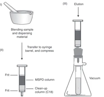
3.3.1 matrix-solid phase dispersion (MSPD)Extraction in which samples are blended with an abrasive solid sorbent, forming a free flowing powder from
which target analytes are recovered by solvent elution.
Note 1: A typical workflow scheme for matrix–solid-phase dispersion is shown in Fig. 8 [30].
Note 2: For additional sample clean-up the sorbent/sample mixture is deposited at the head of a solid-phase extraction cartridge containing a suitable sorbent to retard the elution of matrix components. Reference: [30].
3.3.2 microwave-assisted extraction (MAE)
Leaching using microwave energy to heat the solvent in contact with the sample or the sample directly.
Note 1: Microwaves are electromagnetic radiation of 300–300,000 MHz. They heat the extraction solution by their interaction with dielectric compounds (solvent or sample). Microwave heating is more effi-cient and rapid than convection and conduction and enhances the migration rate of compounds into the extraction solvent. Microwave-assisted extraction may be performed in a closed vessel with control of temperature and pressure or in an open vessel at atmospheric pressure [31].
(I) (II) (III) Blending sample and dispersing material Transfer to syringe barrel, and compress
MSPD column Frit
Frit Clean-upcolumn (C18)
Vacuum Elution
Fig. 8: Typical work flow scheme for solid-phase matrix dispersion. (i) Sample is blended with an abrasive sorbent, (ii) free
flowing powder containing sample is packed in a short column, and (iii) target analytes are recovered by elution.
3.3.3 pressurized hot-water extraction
subcritical water extraction superheated water extraction
Extraction by water below its critical point (374.15 °C and 22.064 MPa).
Note 1: The solvation properties of water become closer to organic solvents at elevated temperatures [32]. Note 2: Instrument requirements are similar to pressurized-liquid extraction.
Reference: [32].
3.3.4 pressurized-liquid extraction
Leaching performed at elevated temperature and pressure.
Note 1: A typical apparatus is shown in Fig. 9 [33].
Solvent Oven Pump Extraction cell Valve Collection vial Gas cylinder
Fig. 9: Schematic diagram of a typical apparatus for pressurized-liquid extraction. Gas flow is used to displace the extraction
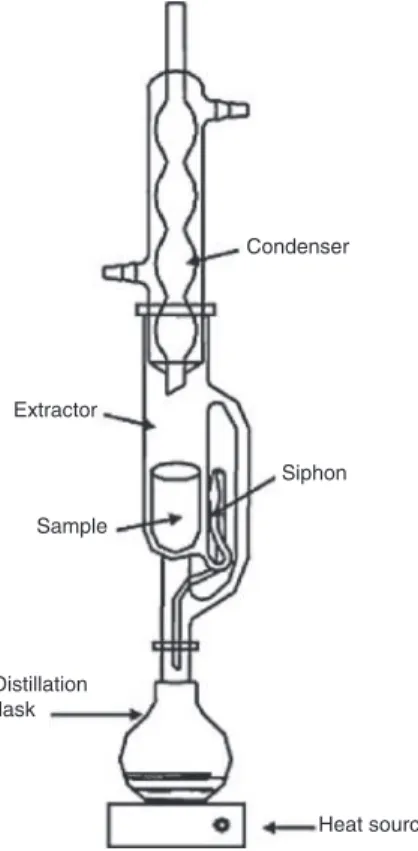
Condenser Siphon Heat source Distillation flask Sample Extractor
Fig. 10: Typical apparatus for classical Soxhlet extraction.
Note 2: The sample, in the form of a fine powder or liquid supported on an inert solid, is packed into an extraction vessel and inserted in a flow-through system. The temperature, pressure, solvent type, and static and/or dynamic extraction time are varied to optimize the extraction performance. Reference: [33].
3.3.5 Soxhlet extraction
Leaching with fresh solvent cycled multiple times through a fine solid sample contained in a porous thimble.
Note 1: A typical apparatus for classical Soxhlet extraction is shown in Fig. 10.
Note 2: The extraction solvent is cycled in a continuous-discrete process by distillation, condensation and siphoning. Extracted material accumulates in the distillation flask.
Reference: [34].
3.3.6 supercritical fluid extraction (SFE)
Use of a supercritical fluid to extract analytes from a solid or supported liquid sample.
Note 1: The powdered sample, or supported liquid, is packed into a vessel and extracted using static or dynamic extraction conditions. The extracted material is typically recovered by reducing the pres-sure of the extraction fluid, allowing it to evaporate [34].
Note 2: The most common supercritical fluid for extraction is carbon dioxide (critical point = 39.9 °C and 73.8 bar). Its extraction properties are varied by changing its density (temperature and pressure) or by addition of polar organic solvents [35].
3.3.7 QuEChERS (Quick, Easy, Cheap, Effective, Rugged and Safe) extraction
Streamlined multiresidue method for extraction and clean-up of analytes in complex matrices. Note 1: Often used for samples containing pesticide residues [37].
Note 2: The general procedure includes micro-scale extraction with acetonitrile, salt-assisted phase separa-tion, and sample clean up using dispersive solid-phase extraction.
Note 3: There are several procedural variations of the general method for application to particular com-pounds or sample matrices.
Reference: [37].
3.3.8 ultrasound-assisted extraction (UAE)
Extraction in which ultrasound energy is used to increase the extraction rate by enhancing the contact area
between the sample and solvent and by promoting efficient agitation.
Note 1: Ultrasound energy is applied to samples in a vessel immersed in a water bath or applied more directly using devices, such as horns, probes, or sono-reactors [38].
Note 2: Ultrasound energy causes cavitation in solvents, which generates numerous tiny bubbles in liquids and mechanical erosion of solids, including particle rupture. It promotes digestion and slurry forma-tion with solids and homogenizaforma-tion and emulsificaforma-tion with liquids.
Reference: [38].
3.4 Digestion methods
3.4.1 acid digestionProcess in which the sample (analyte and matrix) is dissolved by an acid.
Note 1: Acid digestion can also be used to remove a matrix constituent by selective volatilization, e.g. silicon by the use of hydrofluoric acid.
Note 2: Acid digestion can be performed in closed or open vessels. Reference: [39].
3.4.2 ashing (chemical analysis)
Dry or wet matrix decomposition as a method of preconcentration of trace elements. Related term: charring.
Reference: [12].
3.4.3 bomb acid digestion
Type of closed-vessel acid digestion.
Note: Materials which are not fully dissolved by acid-digestion at atmospheric pressure may require a more vigorous treatment in a pressure vessel lined with polytetrafluoroethylene (PTFE) glass, silica, or vitreous (glassy) carbon, or in sealed silica tubes; this treatment is called bomb digestion. The sample and acids are heated in a closed vessel so that the digestion is carried out at higher tempera-ture and pressure.
3.4.4 charring
Pyrolysis of samples containing organic matter. Reference: [40].
3.4.5 closed-vessel acid digestion
Type of acid digestion performed in a closed vessel at elevated pressure.
Note: The increased rate of decomposition and retention of volatile trace elements is an advantage over open-vessel acid digestion.
Reference: [39].
3.4.6 digestion (sample preparation)
Sample dissolution with simultaneous matrix simplification.
3.4.7 enzymatic decomposition
Decomposition of organic materials by the actions of an enzyme whereby high molecular mass compounds are converted into lower molecular mass species.
Reference: [39].
3.4.8 fusion
Chemical process by which a sample is transformed into a glass.
Note: Fusion is commonly employed in XRF analysis. It typically consists of four steps: (1) mixing the sample with a fusion reagent and occasionally with an oxidant, in a crucible; (2) heating the crucible to a temperature where the fusion reagent melts; (3) agitating the crucible until the sample has dissolved; and (4) pouring the molten glass into a hot mould to form a flat glass disk of a given diameter after cooling, ready for measurement in the spectrometer. Alternatively, the molten glass can be poured into a swirling warm acid solvent near ambient temperature for dissolution.
Reference: [41].
3.4.9 microwave acid digestion
Type of bomb acid digestion with microwave radiation used for sample heating.
3.4.10 open-vessel acid digestion
Type of acid digestion performed at ambient pressure wherein the digestion temperature is limited by the boiling point of the acid.
3.4.11 oxygen-flask combustion
Type of ashing in which the sample is burned in a closed flask containing oxygen and an absorbing solution, which is subsequently analysed.
Reference: [39].
3.4.12 partial digestion
pseudodigestion
Digestion in which only a part of the sample, or some of the analytes present, are brought into solution.
Note: Partial digestion may be preferred over total decomposition if the relative analyte concentrations in the samples provides sufficient information (e.g. materials for geochemical exploration).
Reference: [39].
3.4.13 UV photochemical digestion
Formation of free metal ions in aqueous solution by oxidation under the influence of UV light and possibly an oxidizing agent (e.g. hydrogen peroxide or peroxodisulfate) in order to break down dissolved organic matter and metal complexes.
Note: Typical samples are sea water, waste water, drinking water, or fresh water. Reference: [39].
3.5 Solid-phase extraction
3.5.1 cartridgeShort disposable column containing a bed of porous particles immobilized between two porous frits. Note: The particles are sized to allow sample processing by gravity, gentle suction or low pressure. References: [42, 43].
3.5.2 conditioning solvent
Small volume of solvent used to prepare the sorbent for efficient sample processing.
Note: Principal roles include removal of contaminants from the sorbent bed’ to create the conditions for a stable flow of the sample solution during sampling and to facilitate wetting of hydrophobic sorbent surfaces before applying aqueous samples.
3.5.3 elution solvent
Small volume of strong solvent used to displace target analytes from the sorbent bed.
3.5.4 foamed polyurethane sorbent
Sorbent consisting of spherical, micron-sized, agglomerated particles bound together in a rigid and highly porous structure used for the extraction of semi-volatile organic compounds from air in high-volume samplers. Note 1: Their main attribute is their favourable aerodynamic properties, which permit sampling at high flow
rates.
3.5.5 immunosorbents
immunoaffinity sorbents
Porous material with surface bound monoclonal or polyclonal antibodies capable of selective extraction of target analytes by formation of reversible antibody-antigen (compound) binding complexes.
Note 1: A high level of selectivity is possible due to the specificity of antibody-antigen spatial fitting and interactions.
Note 2: The porous support is chosen to minimize nonspecific matrix interactions to facilitate processing complex biological, environmental and food samples without additional clean up.
3.5.6 inorganic oxide adsorbent
Adsorbent with site-specific polar and ion exchange functional groups that extract analytes from a gas or
liquid phase by their complementary interactions with the surface.
Note 1: Typical inorganic oxide adsorbents include silica gel, alumina, magnesium silicate (Florisil), and zirconia.
Note 2: Compounds with hydrogen-bonding or ionic functional groups are extracted efficiently, while neutral dipolar compounds are extracted to a lesser extent and weakly polarizable compounds to a limited extent.
3.5.7 ion-exchange sorbent
Porous material containing fixed ionic sites with a complementary charge to that of the target analyte(s). Note 1: Ionic or ionizable compounds are extracted almost exclusively from water by electrostatic
interac-tions with ion-exchange sorbents.
Note 2: Ion-exchange sorbents are usually classified as weak or strong depending on the identity of the ionic group and whether its charge is independent of the sample pH (strong ion-exchanger) or can be varied by changing the sample pH (weak ion-exchanger).
3.5.8 low-specificity sorbents
Sorbent with a non-selective surface used almost exclusively to extract analytes from an aqueous solution.
The sorbent has a largely passive role in the extraction, with the driving force being the expulsion of the organic contaminants from water to minimize disruption of the water structure.
Note 1: Typical low-specificity sorbents are chemically-bonded porous silica, hydrophobic macroporous polymers, and various forms of carbon.
Note 2: Low-specificity sorbents have surfaces with a low concentration of polar functional groups and retain compounds mainly through non-selective dispersion interactions.
Note 3: From the gas phase compounds are extracted by non-polar and weakly polar interactions with high surface area sorbents.
3.5.9 magnetic nanoparticle sorbent
Sorbent consisting of nanometre-sized, spherical particles with a magnetic or magnetisable core surrounded
by a sorbent shell.
Note: Magnetic nanoparticles have a high surface area-to-volume ratio and a low mass. They are easily dispersed in solution. A magnet facilitates recovery of the nanoparticles from the sample solution or suspension [44].
3.5.10 microextraction by packed sorbent (MEPS)
Solid-phase extraction using a syringe with a short sorbent bed located between the plunger and the needle.
Note 1: Typically based on a 100- or 250-µl volume syringe with a packed bed containing 1–2 mg of sorbent.
Note 2: The MEPS syringe facilitates low-dead volume sample processing by vertical movement of the plunger.
Reference: [45].
3.5.11 mixed-mode sorbent
Porous material with surface co-bonded ion exchange and alkyl functional groups.
Note: The dual extraction mechanism allows fractionation of mixtures into a neutral and acidic fraction and a basic fraction by a stepwise change in pH of the eluting solvent.
3.5.12 molecularly imprinted polymer sorbent (MIPS)
Porous polymer sorbent with synthetic recognition sites with a high specificity for the sorption of a targeted compound or group of structurally-related compounds.
Note: The imprint is obtained by the co-polymerization of functional and crosslinking monomers in the presence of a template molecule (the analyte) and a porogen. The resultant imprint possesses a steric (size and shape) and chemical (spatial arrangement of complementary functional groups) memory of the template molecule that enable the sorbent to selectively rebind the template mol-ecule from a complex matrix.
3.5.13 multiwell extraction plate
Regular array of wells in a single moulded body with a short sorbent bed or disc embedded at the base of each well.
Note 1: The design of a typical multiwall extraction plate is shown in Fig. 11.
Note 2: Multiwell plates typically contain 24, 96, 256, or 384 wells with volumes varying from about 0.1 to 10 ml. They are used for parallel sample processing in high throughput applications.
Reference: [46].
3.5.14 needle trap
Gas-tight syringe with a sorbent-filled needle.
Note: Vertical movement of the plunger allows bidirectional flow of sample through the sorbent bed (active sampling). Alternatively, sampling can occur by diffusion of analytes into the syringe needle (passive sampling).
Reference: [47].
3.5.15 particle-embedded glass fiber disc
Suspension of micron-sized sorbent particles woven into a glass fiber matrix. Note: Small discs are self-supporting while larger discs require external support.
3.5.16 particle-loaded membrane disc
Suspension of micron-sized sorbent particles distributed throughout a web of poly(tetrafluroethylene) micro-fibrils formed into a thin disc of various diameters.
Note: For general use the flexible discs are supported on a sintered glass disc in a filtration apparatus using suction to generate the desired flow through the membrane.
3.5.17 restricted-access sorbent
Porous material with a biocompatible outer surface and a retentive interior surface.
Note 1: Access to the retentive interior surface is restricted for macromolecules by a physical or chemi-cal diffusion barrier that facilitates elution of macromolecules and extraction of low-mass compounds.
Note 2: The restricted access barrier can be accomplished by size exclusion, differential partitioning, or other phenomenon.
3.5.18 rinse solvent
Weak solvent used to displace matrix components from a sorbent without displacing the target analyte(s). Note: An optional step, intermediate between sample application and elution.
3.5.19 solid-phase extraction
Extraction of analytes from a gas, liquid, or fluid by transfer to a solid sorbent.
Note: Typical uses of solid-phase extraction include isolation, concentration, solvent exchange, and
matrix simplification. A 1 2 3 4 5 6 7 8 9 10 11 12 Prefilter Membrane B C D E F G H
3.5.20 solvent desorption
Use of a solvent, typically combined with agitation, to remove target analytes from a sorbent.
3.5.21 sorbent-containing pipette tip
A disposable pipette tip with a small packed bed, disc, or monolithic plug of sorbent at its narrow end. Note 1: A typical design of sorbent-containing pipette device for high throughput sample processing is
shown in Fig. 12 [48].
Note 2: A micropipettor is used to control sample processing steps. This arrangement facilitates the use of bidirectional flow (the cycling of sample and solvents across the sorbent bed in either direction) for sample processing.
Reference: [48].
3.5.22 sorptive-tape extraction
Extraction from the surface of a solid by sorbent or polymer film in the form of a tape in direct contact with, or
in the headspace above, the sample.
Note: The tape is typically a suitably-sized sheet of poly(dimethylsiloxane) polymer, or a piece of particle-loaded membrane, with a large surface area-to-volume ratio.
3.5.23 stir bar sorptive extraction
Extraction of compounds from solution by a sorbent coated magnetic stir bar by rapid stirring (direct
immer-sion) or by exposure to the headspace above a sample (headspace extraction).
Note 1: Related devices for simultaneous stirring and sampling include rotating disc, stir rod, and stir mem-brane devices [49].
Note 2: Rapid stirring accelerates mass transfer overcoming some of the limitations of diffusion controlled mass transfer in sessile solutions.
Reference: [49].
3.5.24 surface-bound macrocyclic sorbent
Porous sorbent with surface bound macrocyclic ligands designed for the extraction of metal ions and some anions from aqueous solution.
Note 1: The selectivity of the extraction process depends on the stability of the host-guest complex, which can be optimized for individual ions by the choice of the macrocyclic cavity and the type of donor atoms.
Note 2: Extracted ions are recovered by elution with a solution of complexing agent with a higher binding constant than the surface-bound macrocyclic ligand.
3.5.25 surface-bound phenylboronic acid sorbent
Porous sorbent with surface-bound phenylboronic acid groups for the selective extraction of bifunctional compounds by reversible formation of 5- or 6-membered covalent cyclic boronic acid complexes.
Note: Extraction occurs at a basic pH for compounds with hydrogen-donating functional groups on neighbouring carbon atoms (1,2- and 1,3-). The analytes are released by elution with an acidic aqueous-organic solvent solution.
3.6 Solid-phase microextraction techniques
3.6.1 biocompatible solid-phase microextractionExtraction by a matrix-compatible immersion solid-phase microextraction device where the extraction phase
and support are chosen to eliminate matrix interferences.
3.6.2 blade format
Solid-phase microextraction device where the extraction phase (sorbent) is dispersed in the form of a thin
coating on the surface of a blade.
Note: This technique is typically used as a 96-blade brush in conjunction with a multiwell sample plate.
3.6.3 coated vessel format
Sample vessel with sorbent-coated walls.
3.6.4 cold fiber solid-phase microextraction
Solid-phase microextraction in the fiber format with a sorbent temperature maintained below that of the
sample matrix during extraction.
3.6.5 fiber format
Extraction phase in the form of a thin layer supported on a fiber made of inert material, such as fused silica,
3.6.6 headspace solid-phase microextraction
Solid-phase microextraction where the extraction phase is placed in the headspace above the sample.
3.6.7 immersion solid-phase microextraction
Solid-phase microextraction where the extraction phase is immersed directly into the sample.
3.6.8 in-needle capillary adsorption trap (INCAT)
In-tube format device with a sorbent-coated capillary placed inside a needle.
3.6.9 in-tube solid-phase microextraction
Extraction utilizing a coated open tubular or packed capillary tube as the extraction phase in a flow system.
Reference: [50].
3.6.10 matrix-compatible solid-phase microextraction
Immersion solid-phase microextraction where the extraction phase is designed to minimize sorption of
parti-cles or macromolecules present in the sample matrix.
Note: Sorption of particles and macromolecules by the extraction phase is a potential source of inter-ference in the extraction process or subsequent determination of analytes when sampling occurs by direct contact of the extraction phase with the sample. In some cases this can be addressed by incorporation of specific properties in the extraction phase that minimize matrix-extraction phase interactions for problem matrix components.
3.6.11 membrane-protected solid-phase microextraction
Immersion solid-phase microextraction in which the extraction phase is surrounded by a permeable
mem-brane that allows access of analytes to the extraction phase while shielding the extraction phase from matrix components with a potential to interfere in the extraction or subsequent analysis.
3.6.12 particle sorbent (microextraction)
Extraction phase in the form of sorbent particles.
Note: Particles are typically of a nanometre size and applied in the dispersion mode of extraction.
3.6.13 rotating disk sorptive extraction (RDSE)
Sorbent-coated disc consisting of a PTFE base with an integrated magnet and a sorbent film attached to one side.
Note: Facilitates more rapid stirring than conventional sorbent-coated stir bars (see stir bar sorptive
3.6.14 solid-phase dynamic extraction, (SPDE)
Solid-phase microextraction in which the extraction phase is coated on the internal surface of a needle.
3.6.15 solid-phase microextraction (SPME)
Microextraction where the extraction phase is a solid.
Note 1: This term is often narrowly used to describe an extraction process employing a syringe-based sam-pling device with a short length of small gauge solid fiber or wire coated with sorbent attached to one end of the plunger of the syringe to facilitate bidirectional movement of the sorbent-coated fiber (wire) through the syringe needle for extraction, storage, and desorption of extractants. For extrac-tion the sorbent is exposed to the headspace above the sample or immersed directly into the sample solution. Sample components diffuse into and/or onto the sorbent coating until equilibrium is reached. The extractants are subsequently recovered by thermal desorption into a gas stream (typi-cally in the liner of an injection port of a gas chromatograph) or rinsed from the sorbent coating with solvent for determination by other methods.
Note 2: The extraction phase can also be a liquid physically coated on a fiber or wire support.
3.6.16 thin film format
Solid-phase microextraction where the sorbent is in the form of a thin film on a support or self supported membrane.
3.7 Membrane extraction
3.7.1 artificial liquid membraneSee supported liquid membrane.
3.7.2 dialysis
Process of separation of low molecular weight analytes from a matrix by a membrane permeable to all compo-nents of the system except the high molar mass compocompo-nents, and allowing the exchange of the compocompo-nents of small molar mass to proceed in a continuous fashion.
3.7.3 downstream
Side of a membrane from which permeate emerges. Reference: [51].
3.7.4 electrodialysis
Dialysis in which ions are separated by an electrical potential across the membrane.
3.7.5 electromembrane extraction, (EME)
Hollow-fiber liquid-phase microextraction in which the extraction is driven by an electrical potential sustained
between the sample solution and the acceptor phase, separated by a supported liquid membrane. Note 1: A typical experimental arrangement is shown in Fig. 13.
Note 2: Electromembrane extraction is typically performed in three-phase mode (aqueous → organic → aqueous) [52].
Note 3: The sample is agitated or stirred during extraction. Reference: [52].
3.7.6 hollow fiber
Narrow cylindrical tube prepared from a porous polymer.
Note: The internal diameter of the tube is typically 0.5–1.5 mm with walls 100 to 300 µm thick. Fibers are typically prepared from porous poly(propylene), although other materials can be used.
3.7.7 hollow-fiber liquid-phase microextraction (HF-LPME)
Liquid-phase microextraction of analytes from a liquid (or gaseous) sample by a supported liquid membrane
in the form of a porous hollow fiber with solvent-filled pores. The analytes are transferred to an acceptor phase contained in the cavity of the hollow fiber.
Note 1: A typical experimental arrangement is shown in Fig. 14.
Note 2: The supported liquid membrane is generally an organic solvent immiscible with water and the sample an aqueous solution.
Note 3: The acceptor phase can be aqueous, which provides a three-phase extraction system (aqueous → organic → aqueous), or an organic solvent, providing a two-phase extraction system (aqueous → organic) [52].
Note 4: The sample is agitated or stirred during extraction. Reference: [53].
Power supply
Acceptor phase
Hollow fiber with SLM
Sample
+ –
Fig. 13: Typical experimental arrangement for electromembrane extraction of cations (anions extracted by reversing the polarity).
3.7.8 liquid membrane
Liquid phase in either a supported or unsupported form that serves as a membrane between two phases. Adapted from reference: [51].
3.7.9 membrane
Structure having lateral dimensions much greater than its thickness, through which transfer may occur by a variety of driving forces.
Reference: [51].
3.7.10 membrane extraction
Extraction of analytes from a sample by permeation through a membrane.
3.7.11 membrane extraction with sorbent interface (MESI)
Membrane extraction with a sorbent trap for concentration of the permeate.
Note: Typically used in a system consisting of three components: (1) membrane extraction module; (2) sorbent interface; and (3) gas chromatography. A flow of gas is used as the stripping phase to transfer permeate to the sorbent trap for concentration and thermal desorption into the gas chromatograph.
3.7.12 microdialysis
Dialysis by a short length of hollow-fiber membrane used for sampling.
Note: Microdialysis is performed mostly in a living biological system.
Acceptor phase
Hollow fiber with SLM
Sample
3.7.13 microporous filtration (microfiltration)
Separation process whereby particles are removed from a sample by application of hydraulic pressure, which forces only particle-free matrix to flow through a microporous membrane.
Note: Typically the membrane has a pore size down to 0.1 µm.
3.7.14 non-porous membrane
Membrane in which permeation occurs by processes other than flow through pores.
Related term: porous membrane.
3.7.15 parallel artificial liquid membrane extraction (PALME)
Extraction of analytes from aqueous samples in a multiwell plate with a porous membrane at the base of each
well by migration through the solvent-filled membrane pores into an acceptor phase located in each well. Note 1: The solvent-filled filter pores function as a supported liquid membrane typically based on an organic
solvent immiscible with water [54].
Note 2: PALME is usually performed in the three-phase mode (aqueous → organic → aqueous). Reference: [54].
3.7.16 perfusate
Stream of extraction phase entering a dialysis module.
Note: Perfusate is also used to describe the stripping phase in dialysis.
3.7.17 permeate
Stream containing material that has passed through a membrane. Adapted from reference: [51].
3.7.18 permeation
Process by which mass transfer occurs through a membrane.
3.7.19 pervaporation
Membrane-based process in which the feed stream and retentate stream are both liquid phases with the ana-lytes emerging at the downstream face of the membrane as a vapor.
Adapted from reference: [51].
3.7.20 porous membrane
Membrane in which permeation occurs through its porous structure.

![Fig. 5: Typical apparatus for extraction based on sublation. Identification: (1) nitrogen gas supply; (2) rotameter; (3) floatation cell; and (4) sintered glass disc [5].](https://thumb-eu.123doks.com/thumbv2/123doknet/14079157.463359/16.892.82.447.730.1041/typical-apparatus-extraction-sublation-identification-nitrogen-rotameter-floatation.webp)