HAL Id: in2p3-00086831
http://hal.in2p3.fr/in2p3-00086831
Submitted on 20 Jul 2006HAL is a multi-disciplinary open access archive for the deposit and dissemination of sci-entific research documents, whether they are pub-lished or not. The documents may come from teaching and research institutions in France or abroad, or from public or private research centers.
L’archive ouverte pluridisciplinaire HAL, est destinée au dépôt et à la diffusion de documents scientifiques de niveau recherche, publiés ou non, émanant des établissements d’enseignement et de recherche français ou étrangers, des laboratoires publics ou privés.
Theoretical study and experimental result of the RF
coupler prototypes of Spiral2
Y. Gomez Martinez, D. Bondoux, J.M. Carretta, J.M. de Conto, M. Fruneau,
A. Garrigue, D. Marchand, R. Micoud, E. Vernay, F. Vezzu, et al.
To cite this version:
Y. Gomez Martinez, D. Bondoux, J.M. Carretta, J.M. de Conto, M. Fruneau, et al.. Theoretical study and experimental result of the RF coupler prototypes of Spiral2. European Particle Accelerator Con-ference (EPAC’06), Jun 2006, Edinburgh, United Kingdom. Joint Accelerator ConCon-ferences Website, EPAC 2006, pp.3170-3172, 2006. �in2p3-00086831�
THEORICAL STUDY AND EXPERIMENTAL RESULT OF THE RF
COUPLER PROTOTYPES OF SPIRAL2
Y. Gómez Martínez, D. Bondoux, JM. Carretta, JM. De Conto, M. Fruneau, A. Garrigue, D.
Marchand, R. Micoud, E. Vernay, F. Vezzu, LPSC (CNRS/IN2P3-UJF-INPG), Grenoble, France
M. Di Giacomo, GANIL, Caen, France
P. Balleyguier, CEA/DAM, Bruyères-le-Châtel, France
Abstract
Spiral2 is a 40 MeV-5mA deuterons and a 14.5 MeV/u-1mA heavy ions superconducting linac under construction at GANIL. The RF couplers have to provide 12 kW CW power to the cavities at 88 MHz for an accelerating field of 6.5 MV/m. Two solutions corresponding to two different technologies have been designed and two prototypes have been built. We present the technical proposals and issues as well as the results (manufacturing, test at low and high power, multipacting…) leading to the final choice.
INTRODUCTION
The LINAC section of the Spiral2 accelerator will use two different types of λ/4 superconducting cavities (for β = 0.07 and β = 0.12 [1]). Each cavity will be fed via one coaxial RF coupler.
The coupling will be electrical, with an antenna located in the bottom of the cavity. A magnetic coupling loop has not been chosen due to technical difficulties to place such a device on top of the cavity. The couplers will not be adjustable so the RF system will have to manage some reflected power.
The coupler has only one ceramic window. Two types of windows have been studied: a disc-shape window (6mm thickness) and a cylindrical one (34mm length) and two prototypes have been built.
Figure 1: The two kinds of couplers with the disc-shape (up) and the cylindrical (down) ceramics.
The transition from ambient temperature to the Helium temperature (4.2 K) is considered in terms of static and
dynamic heat transfer. Hence, multiple iterations between RF design (HFSS) and thermal calculations have been performed.
MECHANICAL DESIGN
The coupler is mounted standing upright at the bottom of the cavity.
One internal bellows is used for the coupler itself to compensate for misalignments and differential thermal expansions. A second external bellows, connected to the vacuum, is used to compensate for atmospheric pressure and thus prevent strains on the cavity.
The connection to the outside is made from the internal 1″5/8 EIA line to a 1″5/8 EIA - 3″1/8EIA transition. The external feeder to the amplifier is a 3″1/8EIA coaxial line.
Figure 2: Coupling to β=0.12 cavity developed at IPN Orsay (CNRS/IN2P3).
All the coupler components are brazed. The internal antenna is made of massive copper. The external part is made of copper plated (20 µm ± 20 %) stainless steel. An air cooling of the window is made to keep the ceramic window at ambient temperature and to prevent condensation. Internal bellows External bellows 3-1/8 EIA line 1-5/8 EIA line Coupler Cavity Cryostat Vacuum connection Disc ceramic window
Antenna
Ring Cylindrical ceramic window
Skirt
Skirt Antenna
Figure 3: Prototype with disc window (left) and cylindrical window (right).
SIMULATIONS
RF Simulations
The 3-D HFSS code has been used. The antenna part is a 1″5/8 line. The coupler diameter is optimized in the window region to minimize the reflected power. For the cylindrical window we get S11 = -32 dB, and S11 = -50 dB
for the disc.
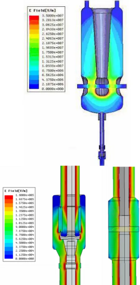
For 20 kW RF power, the maximum value of electric field in the window is about 2.105 V/m for the disc
window and 5.104 V/m for the cylindrical one. So, for
both technologies, moderate electric fields and a good RF transmission can be achieved at 88 MHz.
Figure 4: Electric field in the cavity coupling with the coupler (up), near the cylindrical window (down left) and near the disc window (down right) obtained from HFSS (antenna tip penetration: 13 mm, RF power: 20 kW).
The external quality factor (Qext) at nominal current (5
mA deuterons) varies from 1.3 106 and 2.4 105 depending
on the cavity location. As said before, the antenna penetration is not adjustable and 10 mm has been chosen in order to minimize the RF mismatch in nominal conditions. The external part of the RF system will be designed to handle the reflected power.
Mechanical Stress Simulations
A random vibration study has been made to evaluate mechanical stresses induced by the transport, although the first vibration frequency of the coupler (65 Hz) is above the range of maximal acceleration of transport (from 0 to 40 Hz).
Thermal Simulations
The finite element SAMCEF code is used for thermal calculations. The dissipated power used in thermal simulation is obtained from the three dimensional RF simulations.
During the simulation, the thermal conductivity and electrical resistivity of materials (copper and steel) vary according to the temperature.
The study is made for different residual resistance ratios (RRR) of copper: 10, 30 and 100.
For both technologies, numerical simulations provide similar results. The maximum temperatures at the tip of the antenna and the thermal loads at « cold » links are acceptable.
Table 1: Temperatures (K) of disc window. Copper
RF power Antenna tip temperature
Maximal ceramics temperature
At 0 kW 288 K 288 K
At 20 kW 335.3 K 314.5 K
Table 2: Thermal loads (watts) of disc window. Copper
RF power Thermal load at
4.2K link Thermal load at the cavity (estimation)
At 0 kW 1 W 0.1 W
At 20 kW 1.1 W 0.2 W
Figure 5: Thermal boundaries conditions for the disc window coupler model.
Fixed temperature 300 K
Fixed temperature 4.2 K
Fixed temperature 70 K RRR30.
LOW POWER TEST
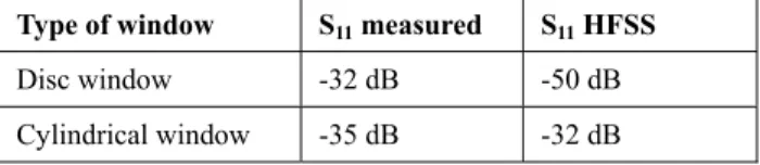
The reflection coefficient S11 has been measured for
both couplers. The theoretical value (-50 dB, disc window) is anyway very optimistic. For both couplers, a value between -32 and -35 dB is obtained, which is acceptable.
Table 3: Comparison of theoretical and measured S11
Type of window S11 measured S11 HFSS
Disc window -32 dB -50 dB
Cylindrical window -35 dB -32 dB
HIGH POWER TEST
Amplifier
A 40 kW tube amplifier is used. The final stage uses a EIMAC triode while the driver is a solid state 3 kW amplifier. A proper adjustment of the transmission line length between the load and the amplifier is needed to be able to handle 100% reflected power at 10 kW.
Test Bench
In classical test benches, a coupler is connected to a waveguide resonator with an output coupler connected to a 50 Ohm load. At 88 MHz, the size of the cavity is prohibitive and a different solution has been chosen. In a first configuration, a coupler is tested in a stand-alone configuration with an open or shorten termination, in a full stationary wave mode. In a second configuration, two couplers are mounted in a push-pull configuration and tested simultaneously in a traveling wave mode. The same bench is used for the two configurations.
Figure 6: Traveling wave test bench.
A directional coupler is used to measure the incident and reflected power.
The vacuum system provides a 3.4 10-8 mbar pressure
comparable to the pressure foreseen in the accelerator. Multipactor is carefully controlled by a continuous pressure monitoring and by an electron pick-up. An interlock system on the vacuum system guarantees any damage on the coupler.
Tests
The Spiral 2 maximum power ( for an accelerating field of 6.5 MV/m) transmitted to the beam is 12 kW CW. Tests in standing wave (with an open circuit and a short circuit) are made up to 10 kW CW and the test in traveling wave is made close to 40kW.
The conditioning time, with a slow power increase, was 196 hours for the disc window (164h in standing wave mode and 32h in traveling wave) and 117 hours for the cylindrical window (85h in standing wave mode and 32h in traveling wave).
In order to reduce these times, a baking is foreseen for the next couplers.
Multipacting
Analytical studies have shown that multipactor may occur mainly at low power, below 100 W. Some pressure increase has been observed in the 0-300W range and not for a higher power. This phenomenon is then not an issue, but a TiN deposition will be made anyway on the ceramics.
Clean Room
The use of the coupler in superconducting cavities requires very clean surfaces. A clean room has been constructed with a system of high purity water (18 MΩ).
CONCLUSIONS
The test results are very good for the two designs. The technologies appear to be comparables, but the disc shape solution is easiest in term of vacuum control and electron pick up set up. This solution has been chosen. The goal is to start now the production of 40 couplers in 2007 and the completion of the production foreseen in 2009.
ACKNOWLEDGEMENTS
Many thanks to T.Junquera, S.Bousson, H.Saugnac (IPNO, IN2P3), T.Garvey, P.Leperqc (LAL, IN2P3), P.Bosland (CEA Saclay) for their very kind help and advices.
REFERENCES
[1] G. Olry et al., “Status of the Beta 0.12
conducting cryomodule development for the Spiral II project ”, this conference.