HAL Id: hal-00199986
https://hal.archives-ouvertes.fr/hal-00199986
Preprint submitted on 20 Dec 2007HAL is a multi-disciplinary open access archive for the deposit and dissemination of sci-entific research documents, whether they are pub-lished or not. The documents may come from teaching and research institutions in France or abroad, or from public or private research centers.
L’archive ouverte pluridisciplinaire HAL, est destinée au dépôt et à la diffusion de documents scientifiques de niveau recherche, publiés ou non, émanant des établissements d’enseignement et de recherche français ou étrangers, des laboratoires publics ou privés.
Spin-dependent diffraction at ferromagnetic/spin spiral
interface
Aurélien Manchon, Natalya Ryzhanova, A. Vedyayev, Bernard Dieny
To cite this version:
Aurélien Manchon, Natalya Ryzhanova, A. Vedyayev, Bernard Dieny. Spin-dependent diffraction at ferromagnetic/spin spiral interface. 2007. �hal-00199986�
hal-00199986, version 1 - 20 Dec 2007
Spin-dependent diffraction at ferromagnetic/spin spiral interface
A. Manchon
SPINTEC, URA 2512 CEA/CNRS, CEA/Grenoble, 38054 Grenoble Cedex 9, France
N. Ryzhanova
SPINTEC, URA 2512 CEA/CNRS, CEA/Grenoble, 38054 Grenoble Cedex 9, France and
Department of Physics, M. V. Lomonosov Moscow State University, 119899 Moscow, Russia A. Vedyayev
SPINTEC, URA 2512 CEA/CNRS, CEA/Grenoble, 38054 Grenoble Cedex 9, France and
Department of Physics, M. V. Lomonosov Moscow State University, 119899 Moscow, Russia B. Dieny
SPINTEC, URA 2512 CEA/CNRS, CEA/Grenoble, 38054 Grenoble Cedex 9, France
(Dated: 20th December 2007)
Abstract
Spin-dependent transport is investigated in ballistic regime through the interface between a ferromagnet and a spin spiral. We show that spin-dependent interferences lead to a new type of diffraction called ”spin-diffraction”. It is shown that this spin-diffraction leads to local spin and electrical currents along the interface. This study also shows that in highly non homogeneous magnetic configuration (non adiabatic limit), the contribution of the diffracted electrons is crucial to describe spin transport in such structures.
The recent observations of current-induced domain wall motion [1] and the investigation of this phenomenon by micromagnetic simulations [2] have underlined the question of spin transport in non homogeneous systems. Although proposed very early [3], current-induced domain wall motion (DWM) has attracted much attention because of its great application potential but also because of the deep fundamental question of the role of electron spin motion in temporally and spacially varying magnetic structures. Zhang et al. [4] proposed an analytical formula for spin torque in slowly varying structures (see eq. 9 in Ref. 4):
T = a∂M
∂t + bM × ∂M
∂t −c1M ×[M × (je.∇)M ] − c2M ×(je.∇)M (1) where M is the magnetization unit vector, a is the renormalization factor of the gyromagnetic ratio and b is the renormalization factor of the damping parameter in the Landau-Lifshitz-Gilbert equation. The last two terms represent the spin transfer torque in spacially varying magnetic structure. The prefactors c1 and c2 are respectively proportionnal to the adiabatic
and non adiabatic contribution. For smooth enough non-homogeneities of the magnetic structure, the adiabatic approximation is usually assumed : the electron spin follows the local magnetization producing a small torque proportional to the spatial derivative of the magnetization [5, 6]. In this case, it is usually accepted that the non adiabatic term c2 is
small but cannot be neglected in domain wall experiments [7, 8]. Furthermore, in spacially non homogeneous systems, c1 and c2 are non local coefficients [5, 6, 9]: at each point of
the structure, one has to consider the contribution of all the electrons flowing through the structure.
In this article, we propose to study the non adiabatic regime in an ”academic” system. We consider two adjacent layers: the left one (z¡0, F) with a homogenous magnetization P = P z and the right one (z¿0, SS - for Spin Spiral) with a 2D helical magnetization contained in the (x,z) plane M = M(sin θ(x)x + cos θ(x)z), where θ(x) = θ0 + Qx. The
interface lies in the (x,y) plane and z is perpendicular to the interface. We consider that the regions are semi-infinite and respectively connected to a ferromagnetic and a spin spiral reservoir. The bias voltage V is applied across the interface.
such as SrFeO3, NaCuO [11], rare-earth based compounds [12] or γ-iron [13]. This helical
structure can be also a simplified picture of narrow stripe domains with domain wall width comparable to domain width.
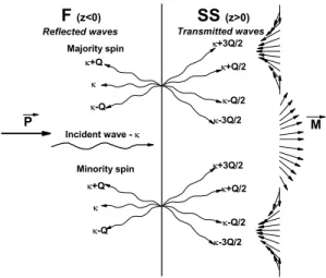
In this case, the adiabatic approximation is no more valid because an electron moving through the interface keeps the memory of its spin state for some distance. Spin-polarized electrons moving from F into SS undergo ”spin diffraction” as represented on Fig. 1: an im-pinging electron with an in-plane incident wavevector κ gives rise to transmitted (reflected) waves with in-plane wavevectors κ + nQ/2 (κ + nQ), 2πQ−1 being the wavelength of the spin
spiral. From the interference of all these waves, one can expect original electrical properties like non-zero torque acting on the magnetization of SS, local longitudinal spin current and even charge current (Hall effect and spin Hall effect [14]) along the F/SS interface.
To model the spin-dependent transport, we use Keldysh out-of-equilibrium technique[15,
16] which expresses the lesser Keldysh Green functions G−+σσ′(rr’) as a function of the basis
of wavefunctions Ψl,rσ(r) for an electron moving from the left (right) to the right (left)
reservoir:
G−+σσ′(rr’) = fl(µl)Ψ∗lσ′(r’)Ψlσ(r) + fr(µr)Ψ∗rσ′(r’)Ψrσ(r) (2)
where fl(r)(µl(r)) are the Fermi distribution functions in the left and right electrodes and
µl(r) are the chemical potentials in these electrodes so that V = (µl−µr)/e. The electrical
current density Je, spin density m and torque T (exerted on SS) are given by the usual local definitions: Je = ℑ[(∇r’ − ∇r)(G−+↑↑ (rr’) + G −+ ↓↓ (rr’))] (3) mx+ imy =< σ+ >= 2G−+↑↓ (rr’) (4) mz =< σz >= G−+↑↑ (rr’) − G −+ ↓↓ (rr’) (5) T = γJsd ¯hµB M × m (6)
where γ is the gyromagnetic ratio, µB is the Bohr magneton and Jsd is the s − d exchange
coupling. The torque T possesses two components: the usual spin transfer torque term (STT, adiabatic torque propotionnal to my and lying in the (x, z) plane), and the field-like
term (IEC, non adiabatic torque perpendicular to the (x, z) plane). The Hamiltonian of the system is then:
H = p
2
2m + U + Jsd(σ.S) (7)
where U is the potential profile, σ is the vector of Pauli matrices and S is the magnetization of the layer (S = M in SS and S = P in F). The wavefunctions are the solutions of the Schr¨odinger HΨ = EΨ. To solve these equation, we used the procedure developped by Calvo[17] in a spin spiral. The boundary conditions of these wavefunctions and their derivatives lead to recurrent relations between the coefficients of these wavefunctions [18]. For example, the wavefunctions of an initially majority electron originating from the left reservoir with in-plane wavevector κ are:
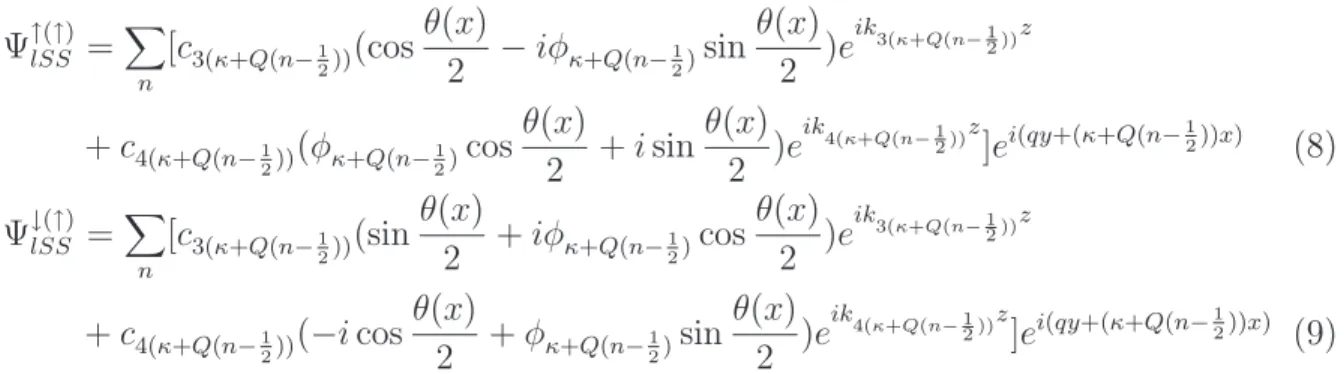
Ψ↑(↑)lSS =X n [c3(κ+Q(n−1 2))(cos θ(x) 2 −iφκ+Q(n−21)sin θ(x) 2 )e ik 3(κ+Q(n− 12 ))z + c4(κ+Q(n−1 2))(φκ+Q(n− 1 2)cos θ(x) 2 + i sin θ(x) 2 )e ik 4(κ+Q(n− 12 ))z]ei(qy+(κ+Q(n−12))x) (8) Ψ↓(↑)lSS = X n [c3(κ+Q(n−1 2))(sin θ(x) 2 + iφκ+Q(n−21)cos θ(x) 2 )e ik 3(κ+Q(n− 12))z + c4(κ+Q(n−1 2))(−i cos θ(x) 2 + φκ+Q(n−12)sin θ(x) 2 )e ik 4(κ+Q(n− 12))z]ei(qy+(κ+Q(n−12))x) (9)
where c3(4) are complex diffraction coefficients and k3(4) are wavevectors for majority
(mi-nority) spin projection in SS. This procedure will be developped in a forthcoming article [18].
For the numerical simulations, we took parameters corresponding to spin transport in Co: the Fermi wavevectors for majority and minority spins are respectively k↑F = 1.1 ˚A−1,
kF↓ = 0.6 ˚A−1; the inverse wavelength of the spin spiral is Q−1 = (2π)−1 ˚A−1 (highly non
homogeneous magnetic system). The Fermi wavevectors of SS and F are the same and we consider the linear approximation : for a small enough bias voltage, only the electrons originating from the left reservoir with an energy located between µl and µr significantly
contribute to the charge and spin transport. We set µl−µr = 38 meV.
Figure 2 displays the longitudinal charge current Je
interface, Je
x oscillates with SS magnetization, but rapidly decreases and vanishes to zero
within 5 ˚A. We observe the same behaviour for the perpendicular current Je
z except it reaches
an averaged value within 5 ˚A. We observe the same features for STT and IEC (not shown here).
This rapid decay is due to interferences between diffracted electron waves. Close to the interface, the averaging effect is smaller than in the bulk SS, so the oscillation amplitude of Je
x(z) and STT, IEC is always higher near the interface than in the bulk.
These damped oscillations strongly depend on the SS wavelength 2πQ−1[18]. Fig. 3
displays the z-dependence of the longitudinal current Je
x [Fig. 3(a)], STT [Fig. 3(b)] and
IEC [Fig. 3(c)] for different values of SS wavelenght Q−1.
When Q increases, the oscillation amplitude of Je
x is reduced so that Jxe vanishes more
rapidly to zero: the increase of the non adiabaticity induces a more important averaging effect due to interference between multiple diffracted waves. STT and IEC have an opposite behaviour when varying Q. The oscillation amplitude of STT decreases when Q increases (similarly to Je
x), whereas the amplitude of IEC increases. This illustrates the different
nature of STT and IEC: STT is the adiabatic torque (vanishes in highly non homogeneous structure) and IEC is the non adiabatic torque (vanishes in adiabatic systems).
This study demonstrates that spin diffraction gives rise to complex characteristic in spin torque and electrical currents and is of seminal importance in non adiabatic magnetic sys-tems.
This work was partially supported within the European MRTN SPINSWITCH CT-2006-035327 and the Russian Fundings for Basic Research 07-02-00918-a.
REFERENCES
[1] P.-O. Jubert, M. Kl¨aui, A. Bischof, U. R¨udiger, R. Allenspacha, J. Appl. Phys. 99, 08G523 (2006).
[2] A. Thiaville, Y. Nakatani, J. Miltat and Y. Suzuki, Europhys. Lett. 69, 990 (2005); S.-M. Seo, K.-J. Lee, W. Kim and T.-D. Lee, Appl. Phys. Lett. 90, 252508 (2007).
[3] L. Berger, J. Appl. Phys. 49, 2156 (1978).
[4] S. Zhang and Z. Li, Phys. Rev. Lett. 93, 127204 (2004).
[5] J. Xiao, A. Zangwill and M. D. Stiles, Phys. Rev. B 73, 054428 (2006).
[6] Y. Tserkovnyak, H. J. Skadsem, A. Brataas and G. Bauer, Phys. Rev. B 74, 144405 (2006); F. Piechon and A. Thiaville, Phys. Rev. B 75, 174414 (2007).
[7] X. Waintal and M. Viret, Europhys. Lett. 65, 427 (2004).
[8] A. Thiaville, Y. Nakatani, J. Miltat and Y. Suzuki, Europhys. Lett. 69, 990 (2005). [9] G. Tatara, H. Kohno, Phys. Rev. Lett. 92, 086601 (2004).
[10] A. S. Panfilov, Low Temp. Phys. 25, 432 (1999).
[11] L. Capogna, M. Mayr, P. Horsch, M. Raichle, R. K. Kremer, M. Sofin, A. Maljuk, M. Jansen, and B. Keimer, Phys. Rev. B 71, 140402(R) (2005).
[12] A. Vl. Andrianov, D. I. Kosarev and A. I. Beskrovnyi, Phys. Rev. B 62, 13844 (2000). [13] M. Marsman and J. Hafner, Phys. Rev. B 66, 224409 (2002).
[14] N. Nagaosa, J. Phys. Soc. Jap. 75, 042001 (2006).
[15] A. Manchon, N. Ryzhanova, N. Strelkov, A. Vedyayev and B. Dieny, J. Phys.: Condens. Matter 19, 165212 (2007).
[16] L.V. Keldysh, Soviet Physics JETP 20, 1018 (1965). [17] M. Calvo, Phys. Rev. B 18, 5073 (1978).
FIGURE CAPTIONS Minority spin Transmitted waves -Q/2 -3Q/2 +Q/2 -Q SS (z>0) F (z<0) Incident wave - +Q +Q -Q +3Q/2 +3Q/2 +Q/2 -Q/2 -3Q/2 Reflected waves Majority spin P M
Figure 1: Cartoon of the bilayered structure. The left semi-infinite layer is a ferromagnet with a homogeneous magnetization and the right semi-infinite layer is a spin spiral with wavelength 2πQ−1. The spin-polarized electrons undergo spin-diffraction at the interface.
0 1 2 3 4 5 -4 -2 0 2 4 x Q / ( a r b . u n i t s ) z (a) -6.525E6 -3.869E6 -1.213E6 1.443E6 4.098E6 6.550E6
-5x10 6 0 5x10 6 -2.0x10 5 -1.5x10 5 -1.0x10 5 -5.0x10 4 0.0 0 10 20 30 40 50 -1.5x10 6 -1.0x10 6 -5.0x10 5 0.0 (b) J e x ( A / c m ² ) (a) S T T ( O e ) (c) I E C ( O e ) Q=1 Q=1.125 Q=1.5 Q=2 z (a)
Figure 3: Longitudinal current (a), usual spin transfer torque (b) and current-induced interlayer exchange coupling (c) as a function of z for different Q (see inset) and calculated at x = π/2Q.