HAL Id: hal-03146724
https://hal.archives-ouvertes.fr/hal-03146724
Submitted on 22 Feb 2021
HAL is a multi-disciplinary open access
archive for the deposit and dissemination of
sci-entific research documents, whether they are
pub-lished or not. The documents may come from
teaching and research institutions in France or
abroad, or from public or private research centers.
L’archive ouverte pluridisciplinaire HAL, est
destinée au dépôt et à la diffusion de documents
scientifiques de niveau recherche, publiés ou non,
émanant des établissements d’enseignement et de
recherche français ou étrangers, des laboratoires
publics ou privés.
MR-ultrasound imaging registration using 2D spatial
phase images
Adrian Basarab, Rémi Abbal, Marius-Cristian Ureche, Denis Kouamé
To cite this version:
Adrian Basarab, Rémi Abbal, Marius-Cristian Ureche, Denis Kouamé. MR-ultrasound imaging
reg-istration using 2D spatial phase images. IEEE International Ultrasonics Symposium (IUS 2012),
IEEE- UFFC Society, Jan 2012, Dresden, Germany. pp.1702–1705, �10.1109/ULTSYM.2012.0427�.
�hal-03146724�
Adrian Basarab1, Rémi Abbal1, Marius-Cristian Ureche2, Denis Kouamé1
1
Université de Toulouse, IRIT, UMR CNRS 5505, France
2
Technical University of Cluj-Napoca, Romania
Abstract — This paper deals with multimodal magnetic
resonance (MR) – ultrasound (US) image registration. One of the major difficulties in such a registration is the lack of correspondence between the gray levels of the pixels in the two modalities. To tackle it, several authors proposed the use of the mutual information as similarity measure in the registration process. Moreover, a few papers proposed recently the use of spatial phase images instead of native intensity images. Phase images have the advantage to contain structural information on the images, free of the energetic information. Although very interesting, to our knowledge only subjective results have been reported concerning the gain of accuracy using phase images. The goal of this paper is to propose a quantitative approach for evaluating the contribution of spatial phase images obtained with monogenic and 2D isotropic analytic signal in MR-US registration.
Index Terms — Affine model, Free-Form Deformation, 2D
Isotropic Analytic Signal, Monogenic signal, MR Imaging, Phase-based multimodal registration, Ultrasound Imaging
I. INTRODUCTION
Image registration in medical imaging is a widely explored research field and has various applications in all standard imagery techniques such as magnetic resonance (MR), ultrasound (US) or computed tomography (CT) [1]-[3]. All these techniques make available to physicians different types of information, which could be complementary and thus could help to improve diagnosis, surgery or therapy. For this reason, the comparison and especially the fusion of information from multiple image modalities is of increasing interest in medical applications. However, in almost all the cases, this comparison and fusion can be possible only after registering the images, i.e. after processing multimodal medical image registration. In this paper, the MR-US image registration problem is addressed.
Generally, medical image registration methods can be divided into two categories: geometric feature-based methods and pixel intensity based methods [4]. The first category presents the inconvenient of being application dependent, in the sense that anatomical landmarks have to be detected in both images before processing the registration. The second category is based on the assumption that a correspondence exists between the pixel intensities of the two images to be registered. For multimodal registration, this correspondence is often measured using the mutual information, which was shown to be more robust than classical similarity measures
such as correlation-based techniques [5]. More recently, a few studies showed interesting experimental results when processing multimodal registration using phase images instead of native intensity of the pixels [1], [3], [6]. However, as in experimental cases the ground truth is not available, these papers only presented qualitative results.
In this context, the main purpose of this paper is to propose a quantitative comparison between MR-US registration using both the native intensity of the pixels and the spatial phase images.
The spatial phase images evaluated herein are obtained using two recent 2D generalizations of the classical analytic signal. These spatial phase images have the advantage of providing structural information, free from the energetic information. Unlike the 1D analytic signal which has a complex representation, its generalizations to the two dimensional case are hypercomplex signals, having two (for the monogenic signal [7]) or five (for the 2D isotropic analytic signal [8]) imaginary components. A brief reminder concerning the monogenic and 2D isotropic analytic signal is given in section II.
To perform a quantitative comparison, we propose in section III a realistic simulation method allowing the control of the deformation field. For this, an ultrasound image simulation is proposed, starting from a real MR image.
In order to evaluate the contribution of spatial phase images to MR-US imaging, a state-of-the-art registration algorithm has been used. Based on the mutual information and on a multi-scale approach, it searches for a local affine transformation. The scope of the paper is not to evaluate the performance of this registration method, but to evaluate the results obtained by applying it to the native images or to the corresponding spatial phase images.
II. HYPERCOMPLEX SIGNALS
In 1D signal processing, the complex representation of a real 1D signal, called analytic signal, has been introduced by Gabor in 1964 [9]. Starting from a real value signal
s
(t
)
, the analytic signal has complex valuess
A(
t
)
=
s
(
t
)
+
is
H(
t
)
,where the imaginary part
s
H(t
)
corresponds to the Hilberttransform of
s
(t
)
. The major contribution of the analytic signal is the possibility to define the concepts of instantaneous (or local) amplitude and phase.MR-ultrasound imaging registration using 2D
spatial phase images
The extension of the analytic signal to not straightforward as it requires the g Hilbert transform to the 2D case.
Chronologically, the first attempts to analytic signal to images were based on co on the so called total or partial 2D Hilbe are direct extensions of the 1D case different ways the real image with transforms, several 2D analytic represen have been proposed, such as the total, par analytic signal [11]-[12]. Despite intere several applications, these 2D analytic sig generalization of the 1D analytic signal, e the lack of isotropy. The isotropy is a cruc to obtain a proper representation of the lo the invariance-equivariance. In other word complex numbers are able to represe freedom. In the case of 1D signals, they ar local amplitude and phase. However, degree of freedom appears, namely the l this reason, it has been recently shown th complex numbers is necessary in orde generalization of the 1D analytic signal [7 complex representations of real images a signal [7] and 2D isotropic analytic si practical aspects of both of them are given 1) The Monogenic Signal
The monogenic signal (MS) was intr and Sommer in 2001 [7]. The main idea combine the local phase with the local orie or in other words to combine the 1D ana local orientation. For this reason, the MS intrinsically one dimensional ima
) n x n x ( ) x , x ( 1 2 = r 1 1+ 2 2 p , for any 1D
the orientation of the vector n=[n1 n2]
orientation of the image structures, de following. A typical example of an i1D Figure 1(b), representing an orientated 2D The monogenic signal of an image de obtained from the responses to three 2D filters (SQF): one even part consisting in band-pass filter (B(u)) and two odd parts c Riesz transform [7]. In the literature, Poisson (or Difference of Poisson, DoP [14] as band-pass filter. ( ) ( ) ( ) (x b x x x y x M p iq jq I = + +
Where x is the vector corresponding to of the pixel andPb(u)=P(u)⋅B(u)is the sp
pass filtered image. Capital letters repre Transform of corresponding images and u frequency variable. As explained above, parts are obtained by two quadrature filter which turn in the Fourier domain in:
) ( ) ( ) ( ) (u H u Bu P u Qx = x ) ( ) ( ) ( ) (u H u Bu Pu Qy = y o image processing is generalization of the o generalize the 1D omplex numbers and ert transforms, which [10]. Combining in these 2D Hilbert ntations of an image rtial or single orthant sting properties and gnals are not a strict especially because of cial property in order cal phase that fulfills ds, we can notice that ent two degrees of re represented by the for images, a third ocal orientation. For hat the use of hyper-er to obtain a strict
7], [8]. These hyper-are called monogenic
ignal [8]. The main n below.
roduced by Felsberg behind the MS is to entation information, alytic signal with the is adapted to locally ages (i1D), i.e. function r(x), where represents the local enoted by ș in the image is shown on D cosinusoid. enoted by p(x1,x2) is spherical quadrature n a rotation invariant constructed using the authors mainly use P) [13], or logGabor
)
x (1)
o the position [x1, x2]
pectrum of the band-esent the 2D Fourier
u = [u, v]T is the 2D , the two imaginary rs hx(x)and hy(x),
(2)
(a)
Figure 1. Examples of (a) i0
With
u
u i u
Hx( )=− ,
From the monogenic sign amplitude, phase and orientat wise formulas given in [7 corresponding to the phase.
¨¨ ¨ © § = − x ( tan ) x ( 2 1 pb MS ϕ
2) The 2D Isotropic Analytic In order to overcome the li images, the 2D isotropic an recently introduced by Wietz the MS by using the first an The second order Riesz tr frequency domain by:
2 2 ) ( u u u Hxx =− Hxy(u)=− Consequently, in addition to we obtain three new second
) (x
xx
q , qxy(x)and qyy(x). Before extracting features su necessary to compute three in
(
( ) 2 1 ) (x xxx s q q q = + ) (x q q+ =(
( 2 1 ) (x qxx q+− = Moreover, a so called ap opening angle, can be calcula (9) and quantifies the intrinsic 0 means that the image is loca¨¨ ¨ © § − = + − ( ) tan ) ( 2 2 1 x x q qs α
The homogeneous signal computed from the apex angl
1 ) (x = +
h
q
Normalizing the first order to extract local main orientat interpretation is equivalent t the monogenic signal. Conc replaced, for the 2D IAS, by:
(
¨ ¨ ¨ © § + = − − 2 1 2 ) x ( tan ) x ( h b DIAS q p ϕ (b) (c)0D, (b) i1D and (c) i2D signals [8].
u
u i v
Hy( )=− (3)
nal, local features such as local tion are extracted using the pixel-7]. Herein, we remind the one
¸¸ ¸ ¹ · + + (x) (x) ) x ) x ( 2 2 2 1 q q pb (4) c Signal
imitation of the MS related to i2D alytic signal (2D IAS) has been zke et al. [8]. The 2D IAS extends d second order Riesz transforms. ransforms are expressed in the
2 u uv − 2 2 ) ( u u v Hyy =− (5)
the three components of the MS, d order components denoted by uch as phase or orientation, it is ntermediate components:
)
( ) 2 1 ) (x b x yy p q = (6) ) (x xy q (7))
) ( ) (x −qyy x (8)pex angle α(x), also known as ated from the 2D IAS as shown in c dimension of the image. α (x) = ally i1D around the position x.
(
)
¸¸ ¸ ¹ · + + − − + − + + ) ( ) ( ) ( ) ( 2 2 2 x x x x q q q (9) l component qh(x) is further e. ( ) 2 ) ( cosα x (10) r signal components, it is possible tion, phase and amplitude, whose to the information obtained with cerning the spatial phase, (4) is) (
)
¸¸ ¸ ¹ · + − −1(x) (x)2 1(x) (x)2 ) x ( y h x h b q q q p (11)It is obvious that for α (x) = 0, qh(x)= 1 and therefore (11) is simplified to (4). In this case, the image is intrinsically 1D.
III. MRI-US SIMULATION
Quantifying the performance of MRI-US registration techniques is a complicated task when doing it on in vivo images. Indeed, in such experimental cases, the ground truth is not available and only subjective measures can be exploited, using for example fiducial markers manually identified and matched on MR and US images.
In this work, we propose to use a realistic simulation in order to quantify the accuracy of MR-US image registration, giving access to the true deformation field. The input of our simulation is an experimental 2D MR image. For illustration purpose, we used herein a gynecological image (a sagittal slice extracted from a MR volume).
1) Scatterer map generation
The property of the tissues exploited in US imaging is their echogenicity, i.e. their ability to reflect ultrasound waves and thus produce echoes. To simulate this process, US simulators generally use scatterer maps. A scatterer is defined by its spatial position and its amplitude. Moreover, the scatterers are positioned following a uniform random distribution. Their number must be sufficiently large in order to insure a density of at least one scatterer per resolution cell. In our simulations, 50,000 scatterers were generated.
An important issue is the way of generating the amplitude of the scatterers. For this task, we propose to link their amplitude to the grey levels of the MR image (denoted by I). By proceeding in this way, we make the assumption that the US echogenicity of a tissue is directly proportional to the MRI T2 relaxation time. For a scatterer i at the position (x1i,x2i), its
amplitude denoted by ai has been randomly generated using a
zero mean Gaussian distribution:
( )
(
i i)
i I x x
a %Ν0, 2 ~1,~2 (12)
The variance of the Gaussian law is related to the grey level of the MR image as shown in (12). The coordinates
(
~
x
1i,
~
x
2i)
stand for the closest pixel position in image I to the position (x1i,x2i) of the current scatterer.
It should be noticed that the assumption of direct proportionality between the echogenicity of a tissue and the T2 relaxation time in MR may not be always valid. In this case, our simulation framework still remains valid, but the way of generating the scatterer amplitudes in (12) should be adapted. In Figure 2, we show an example of a generated scatterer map.
Figure 2. Uniformly random distributed scatterer map.
2) US image simulation
The scatterer map generated as explained above was used to simulate an US images using Field II simulator program [15]. Without loss of generality, US images in linear geometry (corresponding to a 1D linear probe) were simulated.
In our experiments, a 256 elements linear ultrasound probe with 64 active elements was simulated. The width of one element was set at 0.22 mm, the kerf at 0.011 mm (which resulted in a pitch of 0.231 mm) and the height at 5 mm. The central frequency of the probe was fixed at 7MHz, with an axial sampling frequency of 100MHz. The impulse response of the emit aperture was a two-period sinus of the nominal frequency (the excitation) multiplied by a Hanning window. The reception aperture was also a 64-length Hanning window. A multiple point focalization was simulated for the reception.
An example of a simulated US image, as well as the native in vivo MR image, is given on Figure 3 (b and c).
(a) (b) (c)
Figure 3 (a) Original MRI slice, (b) deformed MR image with a known deformation field (affine in this example) and (c) simulated ultrasound image after generating a scatterer map starting from the
image in (b). 3) Deformation field
A known deformation field was imposed to the MR image before scatterer map generation and US simulation, as shown in Figure 3. In this paper, two different types of deformation fields are considered: an affine transformation and a cubic B-spline free form deformation. The choice was made so that the deformation model fits to the ones considered with the two state-of-the-art registration techniques used herein and introduced in [16], [17]. In this way, the evaluation of the registration results was limited to the images on which the registration was performed, and was not influenced by a deviation between the model and the imposed deformation map.
IV. RESULTS 1) Affine estimation
Imposed deformation field
The displacement imposed corresponds to a rotation ȡ= /80, to scale factors scx = 5% and scy = -2%, to shear
factors shx = 1% and shy = 2% and to translations tx = 0.5
pixels (or 0.094 mm) and ty = 0.8 pixels (or 0.079 mm). Figures of merit
The evaluation is done through the following criteria: absolute error between the imposed and estimated affine parameters, minimum (14) and maximum (15), mean (16) and standard deviation (17) of the absolute error between the imposed and estimated deformation fields. Denoting by U(x, y) and Uˆ(x,y), respectively V(x, y) and Vˆ(x,y), the lateral
(true and estimated) and axial (true and estimated) deformation fields, the absolute errors and the associated
figures of merit are defined as follows:
) , ( ˆ ) , ( ) , (x y x y x y EΓ = Γ −Γ (13)
(
( , ))
min , E x y m y x Γ Γ= (14)(
( , ))
max , y x E M y x Γ Γ = (15)¦¦
= = Γ Γ= C x L y y x E LC µ 1 1 ) , ( 1 (16)(
)
¦¦
= = Γ Γ Γ − − = C x L y µ y x E LC 1 1 ) , ( 1 1 σ (17)Where " stands for U or V and L and C are the image dimensions.
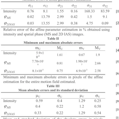
Table I
Absolute errors of affine parameters simulation
11 a a12 a21 a22 a31 a32 Intensity 0.76 8.1 1.55 0.16 168.33 83.59 MS ϕ 0.02 13.79 2.99 0.42 1.5 9.1 DIAS 2 ϕ 0.03 13.55 2.99 0.38 4.75 0.09
Relative error of the affine parameter estimation in % obtained using intensity and spatial phase (MS and 2D IAS) images.
Table II
Minimum and maximum absolute errors
mU MU mV MV Intensity 5.9×1 0-6 1.61 0.67 1.9 MS ϕ 7.78×10 -6 0.81 1.98×10 -5 2.66 DIAS 2 ϕ 8.1×10⁻⁵ 0.75 6.9×10⁻³ 2.58 Minimum and maximum absolute errors in pixels of the affine estimation for the entire motion field estimated.
Table III
Mean absolute errors and its standard deviation
µU σU µV σV Intensity 0.59 0.4 1.29 0.25 MS ϕ 0.4 0.22 1.2 0.58 DIAS 2 ϕ 0.33 0.22 1.29 0.54
Mean and standard deviation of the absolute errors in pixels along the entire estimated affine motion field.
Results
Table I presents the absolute errors of the parameters’ estimation for the affine registration with the native images, with the monogenic spatial phase ϕMS and with 2D IAS
spatial phaseϕ2DIAS. We observe that for a12, a21 and a22 the
intensity-based approach provides slightly less error than the phase-based estimations. However, a11, a31 and a32 are much
more accurate when using phase images.
The consequence of this difference is illustrated in Table II and Table III. Whereas the lateral maximum absolute error is reduces by roughly 50%, the axial error is increased about 50%. This is due to the higher resolution in the axial direction for intensity images and to the band-pass filter degrading the
axial resolution of the phase images. However, the mean absolute errors stay lower or equal than the intensity-based approach, which highlights the interest of the use of phase images. We can also observe that in this experiment, 2D IAS seems to be slightly more accurate than MS.
V. CONCLUSION
In this paper, we considered the use of local spatial phase for MR-US image registration. We tested spatial phases extracted from two different hyper-complex signals: the monogenic signal and its extension, the 2D isotropic analytic signal. A realistic US simulation based on a real MR image allowed us to control the imposed affine deformation field and thus to have access to the ground truth. The obtained quantitative results showed the contribution of the spatial phase images compared to the use of the native gray level of the pixels.
REFERENCES
[1] Zhang, W., Noble, J.A., Brady, J.M. «Real-time 3D ultrasound to MR cardiovascular image registration using a phase-based approach». ISBI, pp. 666-669, 2006
[2] De Nigris, D. and Mercier, L., Del Maestro, R., Collins, D. L. and Arbel, T., « Hierarchical multimodal image registration based on adaptive local mutual information». Medical Image Computing and Computer-Assisted Intervention. vol. 13, pp 643--651, 2010
[3] Zhang, W., Noble, J.A., Brady, J.M. «Adaptative Non-rigid Registration of Real Time 3D Ultrasound to Cardiovascular MR Images». Phys. Med. Biol. vol. 56, pp 117-137, 2011
[4] Makela, T.J., Clarysse, P. Sipilä, O., Pauna, N., Pham, Q.C., Katila, T., Magnin, I.E., « A review of caridac image registration methods».
IEEE Trans. Med. Imag. vol. 21, pp 1011–1021, 2002
[5] Pluim, J.P., Maintz, J.B.A., Viergever, M.A.: «Mutual information based registration of medical images: A survey». IEEE Trans. Med.
Imag. vol. 22, pp.986–1004 , 2003
[6] Mellor, M., Brady, M., «Phase mutual information as a similarity measure for registration». Medical Image Analysis, vols. 9, pp. 330-343,
[7] M. Felsberg and G. Sommer, «The Monogenic Signal», IEEE Trans.
Signal Processing, vol. 49, p. 3136, 2001.
[8] L. Wietzke, G. Sommer and O. Fleischmann, «The Geometry of 2D Image Signals», CVPR, pp. 1690-1697, 2009.
[9] D. Gabor, « Theory of Communications», Trans. Inst. Electr. Eng.,
vol. 3, pp. 429-456, 1946.
[10] H. Stark, «An extension of the Hilbert transform product theorem»,
Proceedings of the IEEE, vol. 59, n° 19, pp. 1359-1360, Sept. 1971.
[11] S. L. Hahn, «Hilbert transforms in signal processing», Artech House, p. 442, 1996.
[12] T. Bulow, G. Sommer, «Hypercomplex Signals - A Novel Extension of the Analytic Signal to the Multidimensional Case», IEEE Trans.
Signal Processing, vol. 49, p. 2844, 2001.
[13] D. Zang, G. Sommer, «Detecting Intrinsically Two-Dimensional Image Structures Using Local Phase», DAGM, LNCS, p. 222, 2006. [14] Vicente Grau and Harald Becher and J. Alison Noble, «Phase-Based
Registration of Multi-view Real-Time Three-Dimensional Echocardiographic Sequences», MICCAI (1), pp. 612-619, 2006 [15] J.A. Jensen, « FIELD: A Program for Simulating Ultrasound
Systems», 10TH Nordic Baltic Conference on Biomedical Imaging, vol. 4, Supplement 1, Part 1, pp. 351-353, 1996.
[16] S. Klein, M. Starling, K. Murphy, M. A. Viergever, J. P. W. Pluim, «Elastix: a toolbox for intensity-based medical image registration»,
IEEE Transactions on Medical Imaging, vol. 29, pp. 196-205, 2010.
[17] A. Myronenko, Non-rigid Image Registration: Regularization, Algorithms and Applications, Oregon Health & Science University, 2010.