Publisher’s version / Version de l'éditeur:
Vous avez des questions? Nous pouvons vous aider. Pour communiquer directement avec un auteur, consultez la première page de la revue dans laquelle son article a été publié afin de trouver ses coordonnées. Si vous n’arrivez pas à les repérer, communiquez avec nous à [email protected].
Questions? Contact the NRC Publications Archive team at
[email protected]. If you wish to email the authors directly, please see the first page of the publication for their contact information.
https://publications-cnrc.canada.ca/fra/droits
L’accès à ce site Web et l’utilisation de son contenu sont assujettis aux conditions présentées dans le site
LISEZ CES CONDITIONS ATTENTIVEMENT AVANT D’UTILISER CE SITE WEB.
Research Paper (National Research Council of Canada. Division of Building
Research); no. DBR-RP-270, 1965-08
READ THESE TERMS AND CONDITIONS CAREFULLY BEFORE USING THIS WEBSITE. https://nrc-publications.canada.ca/eng/copyright
NRC Publications Archive Record / Notice des Archives des publications du CNRC : https://nrc-publications.canada.ca/eng/view/object/?id=fcaa348d-5a0c-4341-92d4-ab6defae1340 https://publications-cnrc.canada.ca/fra/voir/objet/?id=fcaa348d-5a0c-4341-92d4-ab6defae1340
NRC Publications Archive
Archives des publications du CNRC
This publication could be one of several versions: author’s original, accepted manuscript or the publisher’s version. / La version de cette publication peut être l’une des suivantes : la version prépublication de l’auteur, la version acceptée du manuscrit ou la version de l’éditeur.
For the publisher’s version, please access the DOI link below./ Pour consulter la version de l’éditeur, utilisez le lien DOI ci-dessous.
https://doi.org/10.4224/40001466
Access and use of this website and the material on it are subject to the Terms and Conditions set forth at
Effect of moisture on the fire endurance of building elements
Authorized Reprint from the Copyrighted
Moisture in Materials in Relation to Fire Tests
a N k ~
Y Z E DSpecial Technical Publication N o . 385 Published by the
American Society for Testing and Materials 1965
E F F E C T O F MOISTURE O N T H E F I R E ENDURANCE O F BUILDING ELEMENTS1
The effect of moisture on the performance of building elements in fire is closely related to the amount of moisture, and in turn, to the sorption charac- teristics of materials.
High moisture content may result in spalling. The probable mechanism of moisture clog spalling is discussed, and a criterion is developed for the frac-
tional pore saturation at which spalling can be expected (Eq 8).
If spalling does not occur, the presence of moisture is beneficial for the fire endurance. A11 empirical equation has been found which correlates the per- centage gain in fire endurance due to 1 per cent moisture with the fire en- durance in the dry condition (Eq 20). A nomogram is presented to facilitate estimation of the effect of moisture on thermal fire endurance (Fig. 9).
Possible utilization of the results in the field of fire endurance testing is discussed.
T h e realization that the moisture in- If the effect of a variable on the result evitably present in almost any building
matekial may have a marked effect on the performance of building elements in fire, and may present a serious problem in the reproducibility of the results of standard fire tests, prompted a signifi- cant revision of ASTRiI Method E 11g3 in 1959. So significant was this revision that, if enforced retrospectively, it would have invalidated hundreds of fire test results.
Although this revision helped in call- ing attention to the fact that such prob- lems esist, the solution offered b v i t can- not be regarded as more than temporary.
1 Although this pager deals wit11 brick nnd
concrete walls only, most of the conclusions are applicable t o other types of building materials.
? Research officer, Fire Research Section, Division of Building Research. National Re- search Council, Ottawa. Canada.
3,lethods of Fire Tests of Building Construc- tion n ~ ~ d hlnterials (E l l R ) , IIlfi4 Hook of dST.11
Standards, P a r t 14.
of some test is clearly proved, but not knon-n quantitatively, the correct atti- tude is to face the problem by studying
the relation between the cause and efiect
.
One may seemingly dispose of that vari- able by prescribing it a constant value during the test, but further unexpected problems may arise while the basic problem remains unanswered.
Some problems coming in the wake of setting an upper limit to the equilibrium relative humidity' of fire test specimens are already seen clearly, others have so far remained unnoticed. Frequent ques- tions include: ShouId the upper limit be
-
-
1 3 , 70, or 50 per cent? Can forced drying
be pern~itted-:~nd under what conditions?
I!'ill a specimen that satisfies such mois- 'Equilibriun1 relative hunlidity is an n b breviuted tern) me:lni~~ji eqoilibl.ium pressure of water vapor in the lmr.e.5 of solid. e s l ~ r e u > e ~ l a s relative hunlidity.
ture requirements also satisfy the more librium relative humidity. Some ma- basic requirement that a specimen must terials can be forced-dried a t very high be representative of what the actual temperatures, others change signifi- construction is in service? cantly in their characteristic features if
I t is impossible to find valid answers subjected to drying a t an early stage.
FIG. 1-Calculated Sorption Isotherms of a Certain Clay Brick. (a) Adsorption Branch
( b ) Desorption Branch
for all circumstances. Some materials can For some building elements, those to be be tested a t high equilibrium relative erected in dry areas or where the heating humidities without any noticeable effect season is long, the representative mois- from the presence of moisture. Others will ture content may be much less than that yield markedly different performances in equilibrium with 50 per cent rela- even a t 5 per cent change in the equi- tive humidity (RH). In some other
cases, because of specific service con- ditions, an average equilibrium R H
higher than 75 per cent may be antici-
pated.
I t is obvious that none of these prob- lems would arise if the effect of moisture on the fire endurance were known. Test specimens could be subjected to fire tests a t any (or almost any) moisture content; thus, the time devoted to conditioning could serve a very useful purpose-that of attaining the physical properties characteristic of. the material under ac- tual service conditions.
This paper presents the results of in- vestigations into the effect of moisture on the fire endurance of building ele- ments. The possible utilization of the results in the field of fire endurance. test- ing will be discussed in the last section.
The effect of moisture on the fire en- durance of building elements is, of course, closely related to the amount of moisture, and, in turn, to the sorption characteristics of materials. The basic laws governing the adsorption of mois- ture, or adsorbate, in general, by a porous solid (adsorbent) are discussed by Sereda and H ~ t c h e o n . ~ They note that the amount of moisture held by a solid a t
various vapor pressures, in other words,
the shape of sorption isotherms, depends on the specific surface, the effective porosity, and the pore geometry (basic pore shape, pore size distribution, etc.) of the solid, and that in the domain of
Harmathy, in another paper (2), shoivs
how the basic laws of adsorption and some experimental data can be used to estimate the moisture sorption isotherms and isosteres of building materials.
Figure 1 shows the moisture sorption
isotherms of a certain type of clay brick, obtained by calculations. The shape of the curves can be regarded as typical of building materials in general, with the important exception of concrete. In the case of concrete, the hysteresis loop ex- tends to the whole 0
<
p
<
po
pressure range.7 T o understand the cause of this unusual behavior one should realize that the binding energy for some water mole- cules held in the portland cement paste by chemical bonds is less than the energy needed to dislodge the most firmly held adsorbed molecules during drying. Con- sequently, a t some advanced stage of drying, desorption and partial dehydra- tion will take place simultaneously. Since the amount of water held by adsorption cannot be determined exactly, that part of water which is dislodged by some standard drying procedure is more ac- curately called evaporable water, rather than moisture. For similar reasons, the amount of water retained by the hy- drated cement throughout the drying should be termed nonevaporable water. Obviously, in the case of concrete, the reference state of the material is not its "dry" state, but a state determined b y some standard drying procedure. Among the various drying techniques two are generally accepted as standard: (1) dry- ing over ice a t - 78.5 C (sublimationcapillary condensation marked sorption temperature of COJ, so-called D drying,
hysteresis can be experienced. and (2) drying in an oven at 105 C.
Although these sorption characteris- In the light of this discussion it seems
tics can be determined from relatively most probable that the unusual shape of
simple experiments ( I ) , ~ it is often de- sorption isotherms of concrete is due to
sirable to have an estimate of them. partial or complete rehydration, during
adsorption, of the water of constitution
"ee p. 3.
BThe boldface numbers in parentheses refer
lost a t very low prcssui-es during dcsorp- tion.
The sorption charncteristics of port- land cement paste and concrete depend very strongly on the tlegree of Ilytlration
(1,3,4), and thus on the age, conditioning
proced~~rc, and some other factors. Uncler
orclinary circumstances a sufliciently
large mass of concrete can retain enough water in its pores to secure the progress oi hydration for a very long peiiocl after Lhe removal of forms ancl prolecling covers. If, h o ~ ~ ~ e v e r , the concrete is
subjected to forced drying, the hyclralion
slows down considerably as Lhe RH in
the pores becoillcs lo~vcr than 95 per
cent, and stops conlpletely a t 80 per
cent (5).
SPALLIIVG
Because of [he inaikctl diiferences in the sorption charactcrislics of various building materials the nmounl of mois- ture lhat thcse malerials hold a t normal almospheric conditions may be very significant in certai~l cases, or barely noticeable in others.
As a l ~ e a d y mentioned, the presence of
moisture is so~netirnes cletrimen~al, sorne- times beneficial. As for its tletrimental effect, there is now ssuflicient evidence that excessive nioistur~ is a t least one of those factors ivhicli may cause violent spalling of concrete a t some early stage of fire exposure.
The factors atTecting the most colnlnon mode of spalling, the so-callecl thcrmal spalling, have been uncler scrutiny for several dec:~dcs. I t is generally acceptetl that increasing v;llues of the g ~ o u p cj(l - v)/Z<a indicate, a1 least approxi-
mately, a n increasing resistance to
thel-ma1 spalli~lg. 'The (1 - v)/Ea group
al\v.vays appears in ex1,rcssions obtaincd for ~hermnl slresscs in solids, if the calcu-
Inlions are h:~sctl on the assl~mptions that
R , v, an(\ n are constant in the tempera- ture range concernetl, ancl the material
is pcrfeclly elastic. S11ch assl~mptions are
obviously not applicable to concrete,
\irhich exhibits a mixecl elastic-plastic be- havior a t any load even a1 room lenlpcl-a- ture and, owing to cleco~:~position, often mnrked shrin1;agc ins~eatl of e\pansion upon heating. Ilecause of these clin~ac- !crislics, concrelc is rarely lial)le to ~liermal spalling.
A probable mechanism of spalling of
concrele, c:lllctl moisture clog pal ling,^
during fire exposure was clcscribc.d b y Shorter allcl 1-Ialmathy (6) as follo\vs.
\\'lion heat bcgins to penetr:~te into a
concrclc slab, clcsorl)lion of inoistu~c starts in a thin layer adjoini~ig the sur- face exposed to fire. A major portion of the released vapors Ica\~c toward the
colder regions and l~ecome ~c~~clsorbed in
the poi-es of some neighboring layer. As Thc difl'crel~ce I ) C L \ \ ~ C C I ~ tllcr~llill ~ l > ~ H i l l f : a n d moisture clog s p a l l i r ~ g occurring d u r i l ~ ~ : ~ t : ~ ~ ~ ( l u r c l file e l ~ d u r a n c c tests is c:lsil~' ~.cco$- niz:>blc. 1loistul.c clog sl)olling is gcncr:~lIy m o r e violent a ~ ~ c l t l ~ e t l ~ i c k n e s s o l tlic disloclgctl 1ayel.s is greater, a h o u t 1 ill. Sl,alli~ig of concrctc m a y
also b e d u c to other factors, a u c l ~ as cscc.;$ive d e f o r m a t i o n , c s l m n s i o ~ ~ of r c i ~ ~ f o l . c i ~ i g stccl, o r erystallinc t r a ~ i s f o r r l ~ a t i o l ~ in c c ~ t:lir~ aggrcg:ltcs, esl,ecially t l ~ o s c of I ~ i g h rluartz colitent.
the thickness of the dry layer gradually increases, a completely saturated layer of considerable thickness (called a mois- ture clog here), builds up a t some dis- tance from the exposed surface. A little
later, a sharply defined front forms be-
tween the dry and saturated layers (Fig. 2). Further desorption will obviously take place from this frontal area (indicated by Line CD).
I n the meantime the temperature of the exposed surface keeps rising, and a very steep temperature gradient develops across the dry layer resulting in high heat flow and intensified desorption a t the CD plane. Having little passage toward the colder regions, the vapors have to leave through the dry layer, gradually expanding and meeting increasing re- sistance along the flow path. With further steepening of the temperature gradient there will be a rapid pressure buildup a t Plane CD.
If the resistance of the pores to mois- ture flow is not too high, under the effect of the developed large pressure differ- ence, the moisture clog (Region CDEF) begins to move toward the colder regions
and the pressure buildup soon levels off.
If, on the other hand, the permeability
of the material is low, the pressure a t Plane CD continues to grow and will eventually exceed the ultimate tensile strength of the material. When this con- dition is reached, a layer of a thickness approximately equal to that of the dry layer separates from the material.
If this suggested mechanism is correct,
one could expect that material proper- ties, such as porosity, permeability, ultimate strength, and thermal con- ductivity (by affecting the heat flow through the dry layer) will appear in an expression, the value of which deter- mines whether moisture clog spalling will take place at a given moisture content. ~ e c a u s e of the very involved merhanisnl of combined heat and moisture flow, it is
unavoidable to base the derivation of such a criterion on a greatly simplified mathematical model, as follows.
Figure 2 is a schematic illustration of the conditions arising in a concrete slab exposed to fire a t a stage when the forma- tion of the dry layer and moisture clog is completed, and the desorption takes
place from Frontal Plane CD. If it is
assumed that a fraction 6 of the moisture
previously desorbed from Layer ABCD has been readsorbed by Layer CDEL.'. The following relationship is obtairxd
between A and 1
Assuming, furthermore, quasi-steady- state conditions within Region .4BCD,y and applying heat balance to Surface rlB, the surface temperature can be e s - pressed as
and the heat flow as
The rate at which Front CD recedes due to vaporization is1O
The velocity of the moisture clog, Re- gion CDEF, as a whole, can be expressed from Darc>.'s law
K Pi - P s r m
. . .
:,c = -
-
( 5 )7 '1
This is 3 reasunsble nssumption. 0bserx.a- tions 3lld calculntio~ls indicste th:lt within t h e period when sl)nlliilg might occur (10 t o 2.5 rnin in t h e case of standard fire te$tai. the \-ariation rate of the :lx.erage teniperature of the Region
d IiCD is not very sig~iifica~lt.
lo Effective porosity is t h e ~ u l u m e fraction
permeable t o the adsorbate (jvnrer) and i s slightly less than the true porosity.
FIG. 3-lloisture Clog Spalling Lialdity
dyne/cmz, R = 1.0 X 10⁻² J/cm sec deg K. Curve. Assumed Properties: e = 0.30, u, = 17.0 X lo6
The condition r ,
'>
can be inter- 61qh(T,-
T,)A = . . .
preted that the moisture clog moves fast (9) Q P ~
enough to prevent further pressure buildup a t Plane CD. On the other hand, and z.,
<
z l l means that the moisture clog can-B = I l l . . . . . (10)
not yield to the pressure, and the pres-
sure buildup continues owing to increas- and both are considered approximately ing rate of vaporization of Front CD. constant. After assigning plausible values Thus, spalling will take place if to 6, 1, 7, etc. in Eqs 9 and 10
.and B = 3.6 X 1W2 J/cm sec deg K
3 c < 31. . . . . . ( 7 ) or, if one prefers substituting K in darcies,
By combining E q s 1 and 3 to 6, with In- Or in psi, and k in Btu/ft hr deg F e q ~ ~ a l i t y 7, the following criterion is ob- ,I = 0.031 darcies in.2/lb
tained for the fractional pore saturation,
v / / c , a t which disruption of the concrete = 2.1 Btu/ft hr deg
slab is expected Figure 3 shows the variation of allow-
1 able fractional pore saturation with f > - -
1
+
( . l / e ~ u , ) [ k / ( k+
B ) ] . ' (8) permeability, calculated by using E q 8 with c = 0.30, U, = 17 X lo6 dyne/cm2 where (250 psi) and k = lo-? J/cm sec deg KTABLE 1-MATERIALS AND GEOMETRIES STUDIED FOR DETERMINING T H E EXPLICIT FORM OF EQ 12.
No. Material Composition, O/o by weight
1.. . . . .
.
Concrete 1 (as- 15.6 hpcb sumed) 84.4 quartz gravel 2.. . . . ..
Concrete 2 (as- 15.4 hpcsumed) 84.6 anorthosite rock 3. . . . .
.
Concrete 3 (as- 25.3 hpcsumed) 74.7 expanded shale 4.. . .
. . .
Concrete 4 (as- 19.6 hpcsumed) 80.4 expanded shale 5.. . . .
. .
Concrete 5 (exist- 17.5 hpcing) 82.6 expanded shale 6. . . Brown clay brick
.
.
.
(existing)
7 .
.
. . . Insulating fire brick (existing)Pro rties of Moisture Con- Nature of Study X t e r i a l tent, per cent Plotted in by volume
computer calcula- Fig. 4a 0
tions 4.0
8.0 computer calcula- Fig. 4b 0
tions 4.0
8.0 computer calcula- Fig. 5a 0
tions 4.0
8.0 computer calcula- Fig. 56 0
tions 4.0
8.0 fire endurance tests Fig. 6b 0 to 20.8 computer calcula- Fig. Ga 0 to 21.8
tions and fire en- durance tests
fin? endurance tests Fig. 6b 0 to 9.9
a S-3% means solid wall of 339 in. thickness.
1 1 - 7 x 4 3 3 means hollow wall of 73i in. over-all tl~ickness and 83.3 per cent solid.
*
IIydrnted portland cement. Computer calculation^ o~ily.(0.578 Btu/ft hr deg F). If one knows the sorption isotherms of the concrete, the
stile
on the vertical axis can be changed to read RH instead of fractional pore saturation. In Fig. 3 the desorption branch of the isotherm shown in Fig. 1 x a s used to illustrate how the trans- formation of scale is done. (Obviously, the adsorption branch should be used when eaugibrium conditions are attained by wetting instead of drying.)According to Fig. 3, moisture clog spalling is not likely to happen even a t complete pore saturation if the permea- bility of the material is higher than about
5 X 1s" cm2 (0.005 darcies). Although
this value seems to be within the e i - pected range, it should be remembered that at present no experimental proofs are yet available for the confirmation of the validity of Eq 8.
In the case of bricks, the permeability is rarely lev-er than 0.005 darcies, thus moisture clog spalling is very unlikely.
X
recent series of experiments seemed to support this conclusion. I t was also found, however, that brick construc- tions are often liable to thermal spalling. I t may be noticed that the permeabil- ity of mature portland cement pastes is several orders of magnitude lower than that of fresh pastes (3.7); thus, with agingconcretes become more vulnerable to moisture clog spalling.
If spalling is not expected to take place, the presence of moisture in building ma- terials is beneficial for fire endurance. The primary reason is obvious: The absorp- tion of heat associated with the desorp- tion of moisture checks the rise of tem- perature in a building element during fire exposure, delaying the development of various undesirable phenomena which eventually lead to the failure of the build- ing element.
Since, directly or indirectly, it is al-
ways the rise of temperature that causes the failure of a construction, the thermal performance of a building element, ex- pressed in a conveniently defined unit (in terms of thermal fire endurance)" is generally a reliable measure of its overall performance in fire. Thus a figure of merit, expressing tht: beneficial effect of mois- ture on the performance of a construc- tion, can be defined by
This figure of merit of moisture expresses the percentage increase in thermal fire endurance in relation to the percentage (by volume) moisture content. Previous theoretical studies (8) indicated that for
a given material and geometry of con- struction ( T ~
-
~ d ) / ~ , j is approximately proportional to p, thus, in general+
= f (properties of materials, geometry). . (12)but is independent of p.
To determine the explicit form of Eq 12, 90 computer calculations and 49 fire endurance tests have been performed. The materials and geometries studied are summarized in Table 1.
Concretes 1 to 4 are assumed materials: Each was selected to represent an ex- treme case in the group of either dense or lightweight concretes. Since quartz is the best and anorthosite probably the poorest thermal conductor among nat- ural rocks used as aggregates, the thermal fire endurance yielded by Concrete 1 can be regarded as the lowest, and that yielded by Concrete 2 as the highest ob- tainable at a given geometry with dense concretes. Similarly, the prop- erties of Concretes 3 and 4 were se- lected in such a way that no lightweight (nonautoclaved) concrete is expected to
l1 The thermal fire endurance is the time at
which the average temperature on one side of a construction exceeds its initial value by 139 C, when the other side is exposed to a standard
1 I I
-
-
-
-r\l
-
9-
-
- - - Y-
.- 0 - - &I - 2-
ii, - 01-
- .5 2 \ C 0 g--
\-
-
\ 3 c-
\-
E?
\-
- \ I \ \I
/
- I Iyield lower thermal lire endurance than Concrete 3, or higher fire endurance than Concrete 4. The thermal conductivity versus temperature, and heat capacity versus temperature1? curves for these materials (Figs. 4 and 5) are naturally theoretical curves, yet based on numer- ous experimental results and thermo- dynamic data concerning the constituent materials. The methods of calculation
will be reported elsewhere.
The k versus temperature and pc versus temperature cruves for Concrete
5, Brown Clay Brick, and Insulating Fire Brick, are entirely or principally experi- mental curves, determined by means of a variable-state method ( 9 ) .
In all figures the curve sections repre- senting 4 and 8 per cent (by volume) moisture content have been obtained by calculations. The effect of moisture on the thermal conductivity has been evaluated by using a somewhat modified form of Krischer's theory (10).
I t should be emphasized that fire en- durance calculations based on such k
I f Note that in these graphs pc should be interpreted as total heat capacity, obtained as
the tangent to the volumetric enthalpy versus temperature curve (8).
versus T, and pc versus T curves cor- rected for the presence of moisture, could lead to strictly correct results only in the case of such fictitious solids which have zero permeability in the direction of heat flow and infinite permeability perpen- dicular to the heat flow. In such hypo- thetical solids neither moisture (ad- sorbate) nor vapor could migrate along or opposite to the direction of heat flow, and the desorbed vapors could leave the solid infinitely fast along isothermal sur- faces. Real solids, of course, have finite
.ule of Moisture Moment.
permeability in all directions, and since under conditions arising during fire ex- posure, the paths representing the least resistance to fluid flow and the heat flow lines are generally coincident, one can expect marked moisture and vapor mi- gration both along and opposite to the heat flow. As mentioned earlier, the following types of mass migration are conceivable: (1) migration of desorbed vapor in the direction opposite to $e heat flow, primarily under the effect of pressure gradient, (2) apparent moisture (adsorbate) migration in the direction of heat flow by desorption-resorption se- quence, induced by gradients of pressure and of vapor concentration, (3) moisture
(adsorbate) migration in the direction of heat flow under the effect of pressure gradient.
To learn about the probable effect of these migrations on heat transfer, a series of numerical analyses was undertaken to determine the thermal fire endurance of four 32-in. brick walls, all containing 5.3 per cent (by volume) moisture, but dis- tributed over the thickness in different ways. The results indicated that the moisture distribution had a very signifi- cant effect on the thermal fire endurance. I t was found that the'increase in fire endurance was proportional, not to the moisture content, but to its moment about the surface exposed to fire.
This finding, which may be called the rule of moisture moment, is an extremely useful tool of theoretical fire endurance rating. Its application to practical prob- lems is illustrated in Fig. 7 where four different moisture distributions across a wall of thickness L are shown. I n all four cases, the average moisture content is the same, in other words, Areas ABCD are identical. As stated by the rule of moisture moment, the gain in fire en- durance is proportional to the product of Area ABCD and the distance of the cen- ter of gravity of this area from the exposed surface d. I t is now easy to see that the fire endurance corresponding to a distribution shown in Fig. 7a will be less than that corresponding to a distribu- tion shown in Fig. 7b. On the other hand, if the moisture distribution is symmetri- cal about the center line, as in the cases shown in Figs. 7c and 7d, the distance of the center of gravity of Areas ABCD from the exposed surface is always equal to the half thickness of the wall; thus, if Areas ABCD are equal, equal fire en- durances will result.
With the conventional conditioning procedures the symmetry of moisture distribution in wall fire test specimens is always ensured, thus, the result of the
fire test is expected to depend on the average moisture content only, and to be independent of the moisture distribu- tion.
It is now possible to evaluate the ef- fect of the three types of mass flow on the thermal fire endurance. In the case of Type 1 flow the desorbed vapors proceed toward hotter layers, absorb sensible heat, and hinder the flow of heat through the construction. With Type 2 migration the heat flow toward the surface opposite to the fire exposure is aided by a very significant latent heat transfer, but with the displacement of moisture the mois- ture moment gradually increases. Finally, with Type 3 migration a slight increase of heat flow caused by transfer of sensible heat by the moving moisture will be strongly overshadowed by the increase of moisture moment. I t is seen now that migration Types 1 and 3 will definitely, and Type 2 will possibly, result in an in- crease of thermal fire endurance over the value calculable by the assumption of no mass migration along and opposite to the heat flow. I t seems most probable, there- fore, that the ease of mass transfer in these directions, and in turn the perme- ability of the material, is the most im- portant factor affecting the gain in thermal fire endurance.
As Sereda and Hutcheon noted, knowledge in this field has not yet de- veloped far enough to enable one to deal with the ~ r o b l e m of combined heat and mass transfer in its real complexity. From calculations based on the assump- tion of no mass transfer perpendicular to the isothermal surfaces bne can only expect to find the lower limit of the fire endurance of moisture containing build- ing elements. I t will be shown, however, that if combined with experimental re- sults, even this information can be of considerable value.
Although learning about the thermal properties of materials in the tempera-
ture interval of interest generally repre- sents the bulk of the work, there are other wroblems to solve before success- fully calculating the thermal fire endur- ance. First, a rigorous definition of the standard fire exposure should be found which could supplement the vague definition in ASTM Method E 119.
-After evaluating a large number of temwerature measurements taken from the surface exposed to fire of standard fire test specimens, it mas concluded that conditions met during a fire endurance test are well approximated by taking the standard fire exposure equivalent to the transfer of radiant heat to the fire-ex- wosed side of a construction from a black surface, the temperature of which varies according to the so-called time-tempera- ture curve of ASTM Method E 119. Severtheless, to facilitate computer cal- culations, the time-temperature curve Ivas replaced by the following analytic expression
ing it with the Fourier law the following boundary condition results
Within the solid, the heat transfer takes place by conduction according to the Fourier equation
At the surface opposite to fire exposure, the heat transfer is by combined con- vection-radiation mechanism to nonre- flecting surroundings. The radiant heat transfer is again calculable from the Stefan-Boltzmann law. The convective transfer can be described satisfactorily by an empirical equation given by Mc- Adams (12). A combination of these laws with the Fourier law yields the boundary condition for the unexposed surface
Tj = 294.4
+
750[1-
exp (-0.06326tl/Z)] at x = L . .(16)+ 2.&10t1,2. , (13) The initial condition is
This is only slightly different from the so-called
CSTB
function (II), and ap-proximates the time-temperature curve within f 6 C in the 15-min to 8-hr in-
+-...ml
LCI V a l .
The laws governing the mechanism of heat flow through a building element dur- ing fire exposure are fairly well estab- lished. In the case of solid (not hollow) walls the heat flow is one dimensional, and hardly ar;y problem arises. As men- tioned, a t the side exposed to fire, the heat transfer can be regarded as taking place by radiation between a black body of temperature
T,
,
(representing the furnace in standard fire tests) and the surface of the building element a t x = 0, through a nonabsorbing medium. The heat flux can be calculated from the Stefan-Boltzmann law, and b y combin-T = T o , for 0 5 z 5 L, when t = 0 . . (17)
I n all calculations To was taken as 294.4 K. (21.2 C), and e was selected as 0.9-a good average for the materials listed in Table 1. The fact that e de- creases slightly with an increase in temp- erature was disregarded.13
I n the case of hollow walls. the heat flow is, at least approximately, two-di- mensional. Besides the increased labor in solving such cases, a new problem arises -the extremely complicated mechanism of heat transfer within an enclosure bounded by gray surfaces.'* I n the
l 3 Owing t o the very high temperatures the decrease of e may be significant at the exposed surface. This fact, however. has little effect on the result because the heat transfer coefficient is very high anyway, and the heat flux is con- trolled by the thermal resistance of the solid (13).
present series of studies Gebhart's method (10) of calculating the radiation-
exchange in enclosures was utilized. The heat transferred by convection between the surface elements of the enclosure was also taken into account.
All calculations were executed on IBM 1620 and 7090 computers. The computer programs were based on a
course, not a t variance with Eq 12, since r d is function of the properties of materials and geometry of construction.) The $ versus s d plot, based on computed results, is shown in Fig. 8. Although the plot was based on information obtained for five materials of widely different characteristics and several different geometries, all points seem to lie within
0. 1 I I I 1 I I I I I I
C
0 2 4 6 8 10 12
T d h r
FIG. 8-Result of Computer Calculations.
numerical procedure similar to that de- scribed by the author (8). The correctness
of the assumed mechanisms of heat flow, presented by Eqs 13 to 17, was proved by the case of the 24- and 6-in. brick walls (in oven-dry condition), where the difference between the computed and experimental results was iess than 5 min. After expressing the results of com- puter calculations in terms of figure of merit of moisture, it was found that $
could be correlated with s d with fair de- gree of success. (This finding is, of
a relatively narrow band. The best curve representing the mean can be given ap- proximately by
This equation is expected to yield the lowest possible value of $ at a given T d , and is strictly correct only for certain hypothetical materials.
As mentioned, to find the relation be- tween $ and ~ d49 fire endurance tests , were carried out in the second part of
the present series of investigations. All tests were performed on 32- by 32-in. specimens, using an electric furnace with 30- by 30-in. opening. The heat input was controlled to make the furnace tem- perature follow the standard time-tem- perature curve. The temperature of the unexposed surface was measured by three thermocouples placed under as-
construction all specimens were installed in a furnace and dried for 6 hr a t about 105 C. The oven-dry weight of the speci- mens was recorded immediately after their removal from the furnace. Some were tested in oven-dry condition, others were transferred inti polyethylene en- closures for storage and conditioning, Before the scheduled k e test, steam was
FIG. &Result of Fire Endurance Tests.
bestos pads along a diagonal. Although these tests could not qualify in every respect for standard fire endurance tests. experience over several years has shown that there is no significant difference in thermal fire endurance values obtained by these small-scale tests and by full- scale standard tests.
Altogether, 17 specimens were built which represented three different ma- terials and seven different geometries (Table 1). Four to five weeks after their
introduced into the enclosure for a period necessary for the specimen to reach the desired moisture level. The actual mois- ture content was determined by weighing the specimen about 1 hr before the fire test.I5
To obtain a sufficiently large number
16The moisture distribution in the speci- mens was unquestionably symmetrical; there- fore, as noted in connection with Fig. 7 , the distribution of moisture across the specimen was expected to have no effect on the fire endurance test results.
of experimental data, twelve of the speci- mens were subjected to fire test more than once. With specimens made from Concrete 5, some loss of the nonevapor- able water content was experienced fol- lowing the first test. No further dehydra- tion could be detected during subsequent tests. Because the first test had undoubt- edly brought about some permanent changes in the properties of concrete, once-tested concrete specimens were treated as if made from different ma- terial. The ovea-dry weight of repeatedly tested specimens was taken as the weight immediately after the previous test.
The
#
versus r d plot based on this ex- perimental series is given in Fig. 9. The considerable spread of the points may be understood in the light of the following observations: (1) The reproducibility of thermal fire endurance value was f 5 min, (2) The estimated accuracy of the weight measurements was f 100 g, equivalent to a moisture content of fO.l to f0.3 per cent by volume, (3) Undoubtedly, there were more than negligible differences in the properties of specimens of supposedly identical ma- terials.In spite of the considerable spread of points, the following seem to have been proved. In practical cases
#
is always greater than the value calculable with the assumption of zero permeability in the direction of heat flow. (The#
versus ~ d relation corresponding to this assump- tion is a dotted curve in Fig. 9.) As ex- pected,#
increases with the permeability of the material. The experimental results seem to support the assumption that the two most important variables on which#
depends are r d and K , that isAlso,
#
decreases slightly with an in- crease in r d.
The spread of the points in Fig. 9 is somewhat overemphasized by the selec-
tion of the vertical scale. The total range of variation of # is, in fact, not too great (from 3.3 to 7.9); thus, further experi- ments aimed to find an explicit form of E q 19 would serve little practical pur- pose. The accuracy yielded by Eq 20 will probably prove sufficient from the en- gineering point of view
where b is a function of K and can be
taken as:
b = 5.5 for brick, dense concretes, and gun-applied concretes,
b = 8.0. for lightweight concretes, and
b = 10.0 for cellular concretes.
The curves representing Eq 20 with these recommended values of b are also in Fig. 9.
The problenls connected with an ef- fort to standardize the moisture condi- tion of fire test specimens have been dis- cussed briefly. There are great differences in the sorption characteristics of building materials. At normal atmospheric condi- tions many building materials cannot hold sufficient moisture to affect the result of fire test to any appreciable de- gree; therefore, rigid insistence on a single standard conditioning procedure for all materials is inappropriate. On the other hand, for most concretes, the presence of moisture is only one problem, and an all-out effort to reduce the mois- ture content to some standard level may not give the results desired.
There is much information available
(4,15) which shows that at 28 days, even under very favorable conditions, the hy- dration of the portland cement paste is far from being completed. I t is obvious that not only the mechanical, but also
the thermal properties of concrete, are The process of conditioning need no strongly dependent on the degree of hy- longer be regarded as equivalent to dry- dration. Thus, terminating the hydra- ing. On the contrary, this process can tion by subjecting the test specimen to serve its true purpose: the development accelerated drying at an age of 28 days, of the microstructure. which is charac-
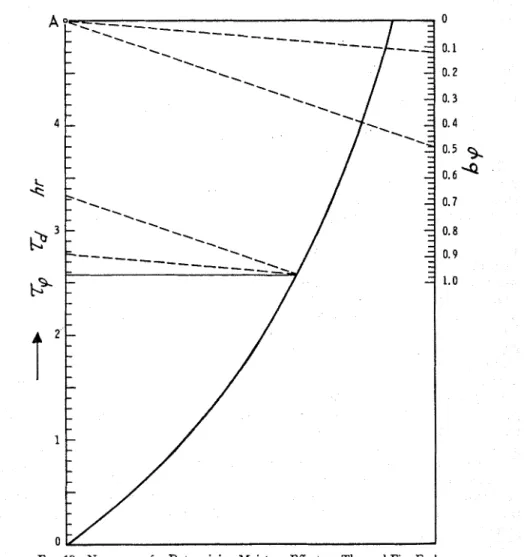
FIG. 10-Nomogram for Determining Moisture Effect on Thermal Fire Endurance. or even earlier, may result in a material
which can hardly be regarded as repre- sentative of what it would become under normal service conditions.
If the effect of moisture on the fire en- durance of a construction is known, the whole problem of conditioning may be considered in a completely different light.
teristic of the material after several years' service.
Storage a t moderately elevated tem- peratures (say 40 to 50 C) in an atmos- phere of higher than 95 per cent RH for a t least one month could probably be regarded as a desirable conditioning pro- cedure for most concretes. I t is known
that up to about 100 C the products of hydration reactions are practically unaf- fected by the temperature (16,17), but the rate of the reactions is greatly increased a t elevated temperatures (4). If the ma-
terial is not expected to spall, after a month of curing, the specimen can be subjected to fire test a t relatively high pore saturation. If the material is liable to spall, forced-drying a t about 90 C may be applied for a short period to reduce the moisture to a level probably to be met under adverse.service conditions.
Of course, the reduction of a fire test result to some other moisture level is pos- sible only if the moisture content of the specimen had been accurately deter- mined prior to the test. The average moisture content of a specimen may be measured fairly accurately by means of a recently described sampling technique (IB), if a sufficient number of samples are taken from well selected locations. Further increase in the accuracy is pos- sible by a combination of sampling and weighing the whole specimen with the aid of load cells.
The correction of a fire test result for a different moisture content has three steps: (I) calculation of r d from experi- mental values of rV and p as described below, (2) application of the experimental or calculated s o r ~ t i o n isotherm to find the value of p under the expected service conditions, (3) calculation of rq corre- sponding to this latter value of p.
Step 1 involves the solution of E q 21, which is a result of combining Eqs 11 and 20, for r d
a nomogram is given in Fig. 10. The same nomogram can be used to find 7, cor-
responding to a new p value which is re- quired in Step 3.
The use of the nomogram is illustrated by this example: A lightweight, concrete- block wall has yielded 3.33-hr fire en- durance when tested a t 6 per cent (by volume) moisture. Question: What is the fire endurance of the wall a t 1.5 per cent moisture?
For lightweight concretes b = 8.0, thus bp = 0.48 for p = 0.06. Connect the point corresponding to this value on the right-hand side scale with Point A . A line drawn parallel to this from 3.33 on the left scale will cut the curve at 2.58 hr which is the value of r d . For p =
0.015, bp = 0.12. Again, connect this point on the right scale with Point -4, and a line drawn parallel to this from the previously determined point of the curve will intersect the left scale at the value of rV pertaining to 1.5 per cent moisture, 2.77 hr, in this case.
It would seem a good practice to re- gard, not the experimental fire endurance, but the value corresponding to the dry condition, r d , as the basic information. This could then be used to assign spec5c values to the fire endurance in specific applications. According to this concept. the mall mentioned in this example may get 3-hr fire endurance when used as an outside wall in certain regions where the average R H is high, but may be regarded only as a 2-hr wall when used as a parti- tion in another region where the winter heating season is long.
where, as mentioned earlier:
b = 5.5 for brick, dense concrete, and gun-applied concrete,
b = 8.0 for lightweight concrete, and
b = 10.0 for cellular concrete.
u
The author thanks S. D. Baster, NRC Computation Centre, and his staff for preparing the computer program, and E. 0. Porteous for carrying out the fire
tests. This is a contribution from the Although the solution of E q 21 presents Division of Building Research, National no problem, to facilitate the calculations Research Council, Canada and is pub-
lished w i t h t h e a p p r o v a l of t h e Director of t h e Division.
S Y ~ O L S
A = constant, defined by Eq 9, dyne
b = factor, function of K , hr
B = constant, defined by Eq 10, J / c m sec deg K
c = specific heat, J / g deg K d = distance, explained in Fig. 7, cm
e = emissivity, dimensionless E = modulus of elasticity, dyne/cm2 f = function
h = heat transfer coefficient, J / c m 2 sec deg K
k = thermal conductivity, J / c m sec deg K
1 = thickness of dry layer, cm
L = thickness of slab, cm
p = pressure, dyne/cm2
fi0 = normal saturation pressure, dyne/ cm2
q = heat flux, J/cm2 sec
Q = isosteric heat of adsorption, J / g t = time, sec
T = absolute temperature, deg K
c = velocity, cm/sec x = variable, cm
Greek Letters:
/3 = constant, 0.000178 J / c m 2 sec (deg K) 514
6 = fraction of vapors readsorbed, di- mensionless
E = effective porosity, cm3/cm3
q = viscosity, g/cm sec (poise)
K = permeability, cm2
A = thickness of moisture clog, cm
Y = Poisson's ratio, dimensionless
p = density, without subscript: bulk density of solid (adsorbent), g/cm3
o = Stefan-Boltzmann constant, 5.67
x
1Wl2 J/cm2 sec (deg K)"uj = fracture stress, dyne/cm2 7 = thermal fire endurance, hr
Q = volume of adsorbate per unit volume
of adsorbent, cm3/cm3
3/
= figure of merit of moisture, defined by Eq 11, dimensionless Subscripts: atm = atmospheric av = average c = of moisture clog d = in dry condition= of the furnace; representing stand- ard fire exposure
1 = a t % = 1
o = a t x
>>
L; when t = 0s = of the surface
cr = coefficient of linear thermal e w a n - w = of water
sion, cm/cm deg K q~ = a t moisture content q~
REFERENCES
(1) T. C. Powerr and T. L. Brownyard, Pro- Mann, Journal, Portland Cement Assn.,
c d i n g s , Am. Concrete Inst., Vol. 43, Research Development Laboratories, Vol. 194-1947, pp. 101, 249, 469, 549, 669, 1, No. 2, 1959, p. 38.
849,933. (8) T. Z. Harmathy, Symposium on Fire Test
(2) T. 2. Harmathy, paper in process. Materials, ASTM STP 301, Am. Soc.
(3) T. C. Powers, Proceedings, Fourth Interna- Testing Mats., 1961.
tional Symposium on the Chemistry of (9) T. Z. Harmathy, Journal Applied Physics, Cement, Vol. 2, National Bureau of Vol. 35, 1964, p. 1190.
Standards, 1962, p. 577. (10) 0. Krischer, Dk ?~issenscItaftlichen Grund- (4) L. E. Copeland, D. L. Kantro, and G. lagen dm Trocknungstechnik, Springer-
Verbeck, Proceedings, Fourth Interna- Verlag, Berlin, 1956, p. 223.
tional Symposium on the Chemistry of (11) J. P. Fackler, "Cahiers Centre Scientifique Cement, Vol. 1, National Bureau of Stand- et Technique du Bktiment," No. 37,
ards, p. 429. Cahier 299, April, 1959.
(5) L. E. Copeland and R. H. Bragg, ASTM (12) W. H. McAdams, Heat Transmission,
Bulletin 204, Feb., 1955, p. 34. Second Edition, McGraw-Hill, New York,
(6) G. W. Shorter and T. Z. Harmathy, Pro- N. Y., 1942, pp. 51, 240.
ceedings, Institute of Civil Engrs., Vol. 20, (13) T. Z. H a r m a t h ~ and J, A. C. Blanchard, 1961, p. 313. Canadian Journal CIzeinical Engineering,
(14) U. Gebhart, H e a t T r u n s j c r , i\IcGra\\-IIill, tional S)nipos~um on the Che~nistry of New YorL, S . V . , 19(jl, 1). 117. Crnlent, Cement Concrete .\ssn., Lontlon, (15) J 13. l ' , ~ p l i ~ i , . l / ~ \ l r < ~ l i u i ~ .JO/OIL~IL .,lppLzed 1954. p. 216.
Science, Vol. 10, 1959, p. 329. (18) T. Z. Hxrnlathy aiid E. 0 . Portcous, B~rild- (16) F. M. I.ea and C H. Desch, 2 ' I ~ e C1len:islry
o j Ceincr!l nird C o ~ ~ c r e l e , Scconci Edition, i,r: S o l e 42. Division Ruiltlii~n Research,
1.:. Arnold, I.onclon, 1956, p. 187. ?i'~Lionnl Research Coi~ncil, Cnr::itla, July, (17) J. D. Bernnl, IJrorecdi7~gs, l'hild Interna- 1963.
DISCUSSION
Cb.
C. CARL SON^ ANI) A t , S. ABRAJCSI-rlSTh4 Conlrnittcc E-5 has long wrestled
with the problcm of inoisture and its proper handling with rcspect to fire tests
and fire elldurance evaluation. Some of
the concepts prescntccl in the paper may provide the answers that Committee
E-5 is seeking.. "
The author's moisture clog concept and the forination of a moisture ladcn layer bchintl thc fire exposed surface of concrete s e e m to provide a plausible
explanation for a phenomenon we have
o ~ s c r v c d in lire tcsts of unrestrainecl, pre- tensioned-prestressed bcams. I n such
tcsts, where the bcams were naturally
dried initially to 70 per cent RI-I in thc deepest scclion (as required by the stand-
ard), we havc seen liquitl water exuding
from the cncls of thc t~vistccl wire pre- stressing strands. The water apparently follo~rrccl the s1nn11 chnnncls available 11ctwccn thc wires. The strands had, in
these instanccs, a minimuin concrete
cover of 2 in. On ot1ii.r occasior-ir, ~v\le wit- ncssecl liquicl water bcing clischargcd under consiclel~ablc pressure into thc hot
furnacc from fir c craclcs ancl surface
blemislles on thc beams. I t appears, holv- ever, that whcn a concretc speci~ucn is
dricd to an cquilibri~~m relative ll~miidity
of 70 pcr cent, thc conclcnsation ancl re- evaporation process is such that clangcr- ous s t e a ~ n pressures are not lilccly to clc- velop. The absence of spaHing ~ v o ~ i l d
1 Manager and senior 1.csearcl1 en::iticer. rcspectivcly, 1;ire IZeucnrch Scctio~l, Ilcscarch
rind D e v e l o p ~ r ~ c n t Laborntorics, I'ortland Ce- ment Assn., Skokie, Ill.
secrn to indicate that the clrying of the concrctc to thc stated cc~uilibrium rela-
tivc hulnidity has procl~~cccl n porc struc-
ture having the proper pernleability for the resulting fractioi-ial pore saturation to prcvcnt a moisture clog buildup. We havc observed, though, that the dangcr of spalling due to thermal stress (thermal spalling) is present when there is heavy restraint of thcrnial expansion. In soine instances (thin slabs within a heavy re- straining frame) the spalling, if one could call it spalling, has been sufficiently violent to fail thc specimen in a single occurrence.
Thc concept of rcfcrring actual fire test results 01) tainecl a t an arbitrarv moisture coiidition to any clesired ill-service condi- tion is incleed ~iscfill. To accomplish this thc author notes: (1) . . The G value of the
inaterial under the cxpected service con- tlitions must bc tlctcrminecl, (2) The moisturc contcnt and prol~crtics of the
material neccssnry for evaluating thc
const:lntTb in Eq 20 for the rccluirecl in- service conditions must be lcnovvn to calculate thc corrcsponcling T , , and ( 3 ) The actual fire test shou!cl be conducted on a specimen which has been condi- tioned in a manner such as to produce a microstructure within the coinpone~lt material n~hich compnrcs with that of sin~ilnl. material after several ycars of service. I t uppears to us that the dctcr- mination of the proper n ~ i c r o s t r ~ ~ c t u r e of thc niatcrinl and the suggcstecl neth hod
for realizing it lnay entail solnc tlificul- ties. However, thesc cIilIiculties are not
insurmountable. The suggested pro- cedure of storing concrete in an atmos- phere a t 40 to 50 C and 95f per cent R H for 30 or more days might serve as a first approximation of the desired end for most concrete mixes and types. In some recent work done at the Portland cement Association Laboratories, a 3 by ft by 6 in. thick, normal weight con- crete slab, moist cured for seven days a t 73 F, followed by drying in air for 21 days at 50 per cent R H a t 73 F, was sub- sequently exposed to air in a kiln a t 85 per cent R H and 150 F (65.5 C) for 2.1 months. The latter treatment was con- sidered productive of a moisture condi- tion in the cooled slab which would be in equilibrium with air at 73 F and approxi- mately 75 per cent RH. The conditioning procedure did produce a fairly uniform humidity gradient of 75 per cent through the section which compared closely with the distribution of moisture obtained in a companion slab of the same concrete naturally conditioned at 35 per cent R H and 73 F for 3.6 months. The fire en- durance of the naturally dried slab was 186 min. This compares with 178 min for the slab conditioned a t 85 per cent
R H and 150 F. The depression of only 8 min in the fire endurance indicates that the microstructure and moisture condi- tion of the specimen conditioned a t 85 per cent R H and 150 F was not greatly different from that of naturally dried (35 per cent R H and 73 F) concrete. Other drying methods which made use of temperatures to 200 F and a very low R H or, that even invoIved subsequent rewetting treatments produced depres- sions in the fire endurance of as much as 20 min.
In conclusion, we would like to con- gratulate the author for his fine contribu- tion to the field of fire research. His approach to the problem of assessing fire resistance of constructions as they will actually be used is in strict conformity with the main purpose of ASTM Method E 119. He has shown that the formidable di5culties of determining moisture effect on the fire resistance of materials can be attacked analytically to produce very useful engineering information. Undoubt- edly, other variables affecting fire re- sistance will also yield to analytical methods.