HAL Id: hal-01022308
https://hal-enac.archives-ouvertes.fr/hal-01022308
Submitted on 22 Sep 2014
HAL is a multi-disciplinary open access
archive for the deposit and dissemination of
sci-entific research documents, whether they are
pub-lished or not. The documents may come from
teaching and research institutions in France or
abroad, or from public or private research centers.
L’archive ouverte pluridisciplinaire HAL, est
destinée au dépôt et à la diffusion de documents
scientifiques de niveau recherche, publiés ou non,
émanant des établissements d’enseignement et de
recherche français ou étrangers, des laboratoires
publics ou privés.
for the modeling of quasi-optical systems
Kevin Elis, Alexandre Chabory, Jérôme Sokoloff
To cite this version:
Kevin Elis, Alexandre Chabory, Jérôme Sokoloff. 3D interaction of Gaussian beams with dichroic
surfaces for the modeling of quasi-optical systems. ANTEM 2012, 15th International Symposium of
ANtenna Technology and applied ElectroMagnetics, Jun 2012, Toulouse, France. pp 1-5,
�10.1109/AN-TEM.2012.6262371�. �hal-01022308�
3D interaction of Gaussian beams with dichroic
surfaces for the modeling of quasi-optical systems
Kevin Elis
Service Antennes
CNES
Toulouse, France
kevin.elis@recherche.enac.fr
Alexandre Chabory, Kevin Elis
Laboratoire Télécom, département CNS
ENAC
Toulouse, France
chabory@recherche.enac.fr
Jérôme Sokoloff, Kevin Elis
LAPLACE
Université Paul Sabatier
Toulouse, France
jerome.sokoloff@laplace.univ-tlse.fr
Full Paper—In quasi-optical systems, dichroic surfaces are
used to split, filter, or mix signals. Such surfaces cannot be modeled by existing Gaussian-beam methods. In this article we propose a technique to model the interaction of a Gaussian beam (GB) with a dichroic surface based on a matching in the spectral domain. For a GB illumination of the surface, the reflected and transmitted fields are approximated by one reflected and one transmitted Gaussian beams. Their charac-teristics are determined by means of the spectral matching through a second-order approximation of the dichroic surface response when excited by plane-waves. Numerical experiments and comparisons with reference solutions show the efficiency of the method in terms of accuracy and computation time.
Keywords-component—Gaussian beam; dichroic surface; spectrum matching; quasi-optics
I. INTRODUCTION
In mm-wave radiometry, quasi-optical systems are used to guide, filter, split, or mix the input signals. Such systems are generally constituted by the combination of different elements, e.g. mirrors, lenses, dichroic filters, or horn antennas. The number and the size of these elements render their modeling difficultly amenable by classical methods [1] in acceptable computation times. For such systems, even physical optics may become computationally costly.
The use of Gaussian beams (GBs) constitute a possible alternative [2]. Such methods are generally divided in two parts. In the first one, the incident field is expanded into a finite sum of GBs. In the second part, the beams are tracked through the system. The interaction of a GB with many elements of quasi-optical systems is well-known. Indeed, in [3], Deschamps has demonstrated that the fields reflected and/or transmitted at a dielectric/metallic moderately-curved interface illuminated by an incident GB can be approximated by Gaussian beams. In contrast, dichroic surfaces cannot be modeled by such methods because they are in some cases structures which period may not exceed a fraction of wavelength [4], [5].
To deal with periodic structures, one generally assumes a plane-wave illumination. The response can then be computed with the help of the method of moments coupled with a Bloch-Floquet modal description [6]. For the modeling of a complete quasi-optical system, one has to integrate this response [7].
In this article, we propose a solution to model the interaction of a GB with a dichroic surface. The method consists in assuming that the fields reflected and transmitted by the interface are GBs. This is realized with a general analytical formulation of GBs that includes the fundamental GB [8]. The characteristics of the reflected and transmitted beams are found by means of a matching in the spectral domain. This involves an approximation of the dichroic surface response for plane-waves illuminations. This article is organized as follows. Details about the configuration are presented in Section II. In Section III we briefly present GBs. Next in Section IV, we explain the spectrum-matching method. Numerical experiments are performed to confront the results with reference methods in the last section.
II. CONFIGURATION
The configuration is presented in Fig. 1. We associate a reference frame (0i, ˆxi, ˆyi, ˆzi) with the incident GB. The
dichroic surface is of arbitrary shape and thickness, and can be associated with a coordinate system(0d, ˆxd, ˆyd, ˆzd).
This dichroic surface is either made of periodic elements or dielectric layers. In order to describe the orientation of the different reference frames, we use the classic definition of Euler angles such as presented in Fig. 2.
The dichroic surface response is assumed to be already known, for example in a tabulated form. In practice, this response can be computed numerically using a method based on Floquet modes, for example via [6].
Fig. 1: Configuration.
Fig. 2: Euler angles.
III. GAUSSIAN BEAMS
A. Definition
Gaussian beams are analytical solutions of the approx-imated wave equation upon the paraxial approximation. This requires that the field is only weakly diverging with respect to its main propagation direction. The maximal angle of divergence generally admitted is of 20o [8].
In this article, we use a formulation as general as possible in order to describe accurately the reflected and transmitted fields. The transverse electric field of a GB in zi=0 is so
that
Et ,i(xi, yi, 0) = ui(xi, yi, 0)£ai xˆxi+ai yˆyi
¤
(1) with ai x and ai y the coefficients associated with the xi and
yi polarization, respectively. Besides ui represents the scalar
GB expression in zi=0, and is given by
ui(xi, yi, 0) = exp h −jk 2¡ρi−ρi0 ¢t Qi0¡ρi−ρi0 ¢ −j βti¡ρi−ρi0 ¢i . (2)
with k the wavenumber and ρi=·xi yi ¸ , ρi0=·xi0 yi0 ¸ and βi0=·βxi0 βy i0 ¸ .
Qi0 represents the complex curvature matrix of the GB.
When diagonal, this matrix can be related to the sizes and the positions of the waists of the GB. From these expressions, in its reference frame the beam is characterized by five parameters, i.e. two complex amplitudes (ai x, ai y),
a complex curvature matrix Qi0, a spectral shift βi0 and a
spatial shift ρi0.
B. Paraxial formulation
Assuming a propagation of the beam towards zi≥0, the
field can be expressed as Ei(xi, yi, zi) = Ï∞ ∞ ˜ Ei(kxi, ky i)e−j k t iridk xidky i (3)
with kti=£kxiky ikzi¤ the wavevector, rit=£xiyi zi¤ and,
˜ Ei(kxi, ky i) = ˜ui(kxi, ky i)ei(kxi, ky i). (4) In this expression, ei=ai xˆxi+ai yˆyi−¡kxi/kziai x+ky i/kziai y¢ ˆzi, (5) ˜ ui= j 2π kpdet(Qi0) exphj 1 2k¡kρi−βi0 ¢t Q−1i0 ¡kρi−βi0 ¢ +j ρti0kρi i , (6) with kρi=·kxi ky i ¸ . Ifβzi0= q k2−β2
xi0−β2y i0<k, the GB spectrum is centered
on a propagative plane wave. We associate with this GB a new coordinate system (0β, ˆxβ, ˆyβ, ˆzβ) such as
xβ yβ zβ =Pi→β xi−xi0 yi−yi0 zi , (7)
where Pi→β is a 3 × 3 transformation matrix from the
incidence reference frame to a new coordinate system with Euler angles (φ0,θ0, 0) as illustrated in Fig. 3.
Fig. 3: Reference frame of the incident GB.
Note that
φ0=angle¡βxi0,βy i0
¢
θ0=acos¡βzi0/k¢ .
(8) In this coordinate system, the asymptotic evaluation of (3) via the steepest descent path method [9] yields the classical paraxial formulation of GB Ei(xβ, yβ, zβ) =ui(xβ, yβ, zβ) · aβxˆxβ+aβyˆyβ −j k µ aβx ∂ui ∂x +aβy ∂ui ∂y ¶ ˆzβ ¸ , (9)
with ui(xβ, yβ, zβ) = q det Qβ(zβ) q det Qβ0 exp¡−j kzβ ¢ . exp µ −jk 2ρ t βQβ(zβ)ρβ ¶ , (10) and Q−1β (zβ) = Q−1β0+zβI, (11)
inside which I is the identity matrix. In the new coordinate system, the beam curvature matrix Qβ0 and coefficients
(aβx, aβy) are given by
aβx aβy 0 =Pi→β ai x ai y −cosφ0ai x−sinφ0ai y , (12) and Qβ0=R−1 t Q−1i0R−1 (13) with R = 1 cosθ0
·cosφ0 −cosθ0sinφ0
sinφ0 cosθ0cosφ0
¸
, (14)
Note that an alternative formulation can be obtained that only depends on the far-field approximation by applying the stationary phase method to (3).
IV. METHOD
A. Principle
We suppose that the incident GB yields one transmitted and one reflected GBs. Because the method is similar for both cases, only the study of the transmitted field will be exposed in details. The transmitted GB must be as close as possible to the transmitted field. Therefore, the goal is to determine its reference frame and parameters.
In order to keep spectrum with Gaussian amplitudes, we make the matching of the incident/transmitted spectrum in the reference frame of the incident beam. Besides, the spec-trum matching is realized on the transverse components of the spectrum. For the incident GB, these components can be expressed as
˜
Et ,i(kxi, ky i) = ˜ui(kxi, ky i)¡ai xˆxi+ai yˆyi
¢
(15) For the transmitted field to be approximated by a GB, its transverse components must be approach by a similar form, i.e.
˜
Et ,t r(kxi, ky i) = ˜ut(kxi, ky i)¡at xˆxi+at yˆyi
¢
(16) The principle of the method can be divided in two parts. We find the expression of the transmitted spectrum from the incident spectrum and the response of the dichroic surface. Then, this expression is matched to (16).
B. Expression of the transmitted spectrum
Each plane wave impinging the dichroic plate is ex-panded in parallel and orthogonal polarizations. For the incident spectrum (4), this yields
˜ EiË=u˜i(ei.ˆeË), E˜i⊥=u˜i(ei.ˆe⊥). (17) with ˆe⊥= ˆsi×nˆd ∥ˆsi×nˆd∥ , ˆeË=ˆe⊥׈si, ˆsi=ki/k, (18)
and ˆnd the normal to the dichroic plate.
Making use of the dichroic surface response, we end up with the orthogonal and parallel components of the transmitted spectrum ·˜ Et rË ˜ Et r⊥ ¸ =·T Ë,Ë TË,⊥ T⊥,Ë T⊥,⊥ ¸ ·˜ EiË ˜ E⊥i ¸ , (19)
where TË,Ë, TË,⊥, T⊥,Ë, T⊥,⊥ are the transmitted coefficients associated with both polarizations. Finally, the transmitted spectrum is expressed as
˜
Et r= ˜Et rˈe
Ë+ ˜
E⊥t rˆe⊥. (20)
Using (17), (19) and (20), the transverse components of ˜Et r
can be formulated as ˜ Et ,t r=u˜i(kxi, ky i)S(kxi, ky i), (21) with S = Sx(kxi, ky i)ˆxi+Sy(kxi, ky i)ˆyi. (22) C. Spectrum matching
To match (16) with (21), we need the following approxi-mation of S(kxi, ky i)
S ≈ Sa=¡sx0ˆxi+sy 0ˆyi¢ exp
³
ktρiρs+ktρiQskρi
´
(23) where (sx0, sy 0) are complex coefficients, ρs is a complex
vector, and Qs is a complex symmetric matrix. (sx0, sy 0) are
obtained by matching S with Sa at the maximal value of
the incident spectrum, i.e. kxi=βxi0 and ky i=βy i0. Then,
we project (23) on¡sx0ˆxi+sy 0ˆyi¢. We end up with
S.³s∗x0ˆxi+s∗y 0ˆyi
´
|sx0|2+ |sy 0|2
≈exp³kρit ρs+ktρiQskρi
´
. (24) This approximation must be valid in the interval where the incident spectrum is significant. In order to obtain these coefficients, we perform a point matching at nine different plane-waves: one at kxi =βxi and ky i =βy i and two at
half of the maximal power of the incident GB spectrum for
D. Identification
From (21) and (23), we find ˜
Et ,t r≈u˜i(kxi, ky i) exp
³
ktρiρs+kρit Qskρi
´
.¡sx0ˆxi+sy 0ˆyi¢ .
(25) We insert (6) and (25) in (21) and we obtain
Q−1t r 0=Q−1i0 −j 2kQs βt r 0=Im¡Q−1 t r 0 ¢−1 ¡Im¡Q−1 i0¢ βi0+kRe¡ρs ¢¢ ρt r 0=ρi0−Im¡ρs¢ +βt r 0Re¡Q −1 t 0¢ − βi0Re¡Q−1i0 ¢ k ·at r x at r y ¸ =·sx0 sy 0 ¸ pdet Q t r 0exp¡ j2k1βti0Q−1i0βi0 ¢ pdet Qi0exp¡ j2k1βtt r 0Q−1t r 0βt r 0 ¢ (26)
We have completely specified the transmitted GB. The reflected beam can be determined in a similar way. Its reference frame is chosen as the image of the incident reference frame. Finally, either the paraxial or the far-field formulation of GBs (9) can be employed to compute the fields at any point of space.
V. NUMERICAL CONFRONTATIONS WITH REFERENCE METHODS
A. Configuration
For validation purpose, we consider a dichroic surface constituted by a thick infinite dielectric slab of relative per-mittivity εr=4 and thickness 2λ0 placed at zi=0.1m. The
Euler angles between the incident beam reference frame and the dichroic plate reference frame are (0◦, 45◦, 0◦). The frequency is set at 100GHz. The configuration is presented in Fig. 4.
Fig. 4: Configuration.
B. Methods
We confront the Gaussian beam matching (GBM) with two reference methods. Because the dichroic surface is only made by large dielectric interfaces, we can compare our results with the GB tracking method (GBT). This method is classically used in GB techniques [2].
The second one is based on the radiation of equivalent currents. They are obtained by modeling the dichroic sur-face by means of the reflexion and transmission coefficients.
This method is denoted “RTC” and is classically used to model dichroic surfaces in quasi-optical systems [7]. Contrarily to GBT, this method is exact but slow.
C. Incident field
The incident beam parameters are ·ai x ai y ¸ =·1 0 ¸ , βi0= ·0 0 ¸ , ρi0= ·0 0 ¸ (27) and Qi0−1= " jkW 2 0 2 −zi0 0 0 jkW 2 0 2 −zi0 # , (28)
with W0=1.5λ0 and zi0=0.1m the sizes and positions
of the beam waist. In other words, the incident field is a fundamental GB polarized according to xi with a waist
placed at the dielectric slab.
D. Results
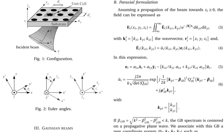
In Fig. 5, we show the total near-field obtained with GBM. In Fig. 6, we display the difference of this result with the reference solution RTC.
(a) kEGB MkdB,φ = 0◦ (b) kEGB MkdB,φ = 90◦ Fig. 5: Normalized total electric field obtained with GBM (dB): (a) plane φ = 0◦, (b) planeφ = 90◦.
(a) kEGB M−ERTCkdB,φ = 0◦ (b) kEGB M−ERTCkdB,φ = 90◦ Fig. 6: Difference with the RTC method (dB): (a) plane φ =
0◦, (b) planeφ = 90◦.
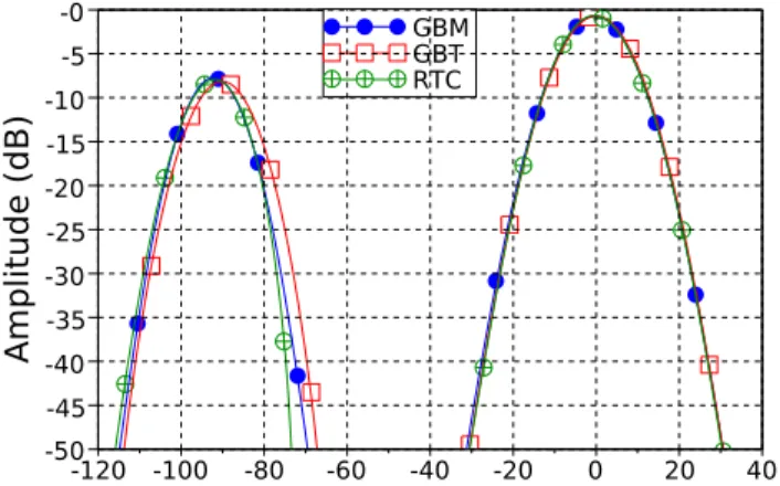
We see that GBM yields very low errors, that mainly originate in the paraxial approximation. This is confirmed by the far-field patterns displayed in Figs. 7 and 8. Beam parameters are modified when passing through the surface, e.g. the spatial and angular shifts are of
·φr e f 0 θr e f 0 ¸ ≈ · 0 −2.2◦ ¸ and ρr e f 0≈·1.7λ 0 ¸ , (29)
for the reflected GB, and of ·φt r 0 θt r 0 ¸ ≈ · 0 −0.3◦ ¸ and ρt r 0≈·−1.12λ 0 ¸ , (30)
for the transmitted GB. The complex curvature matrices of both GBs are significantly modified. Moreover, due to the tracking process, GBT yields several transmitted and reflected GBs, which is not the case with GBM. This explain why GBM outperforms GBT in terms of computation time in this simulation. Note also that we observe in the far-field pattern that GBT does not model the angular shift.
Fig. 7: Normalized far field (dB), reflected (left) and trans-mitted (right). Obtained with GBM, GBT, and RTC.
Fig. 8: Difference of GBM and GBT with RTC in the far field (dB).
VI. CONCLUSION
In this paper, we have proposed a method to treat the interaction of a Gaussian beam (GB) with a dichroic surface. This has been achieved by assuming that the transmitted and reflected fields are also GBs. The method uses general analytical formulations for the GBs that depend either on
a paraxial or far-field approximation. The beam parameters have been obtained by means of a matching in the spectral domain.
To validate these formulations, numerical tests have been performed for a thick dielectric slab. We have presented comparisons with two reference methods in the far-field and near-field zones. We have observed results that show that the modifications of the beam when passing through the surface are correctly estimated, notably the spatial and angular offsets. This method can be used with any incident field represented by a sum of GBs. Thus it can be used to model a complete quasi-optical system that includes dichroic surfaces.
Simulations of a complete quasi-optical system including periodic dichroic surfaces will be realized in future works.
ACKNOWLEDGMENT
The authors would like to thank the CNES and the ENAC for supporting this work under a PhD.
REFERENCES
[1] T. Bondo and S. B. Sorensen, “Physical optics analysis of beam waveguides using auxiliary planes,” IEEE Trans. Antennas Propag., vol. 53, no. 3, pp. 1062–1068, March 2005.
[2] A. Chabory, J. Sokoloff, S. Bolioli, and K. Elis, “Application of Gaussian-beam based techniques to the quasi-optical systems of radiofrequency radiometers,” in EuCAP, Barcelona (Spain), April 2010.
[3] G. Deschamps, “Ray techniques in electromagnetics,” Proc. IEEE, vol. 60, no. 9, pp. 1687–1693, February 1969.
[4] B. A. Munk, Frequency Selective Surfaces: Theory and Design. New York: Wiley, 2000.
[5] C. Winnewisser, F. T. Lewen, M. Schall, M. Walther, and H. Helm, “Characterization and application of dichroic filters in the 0.1-3-THz region,” IEEE Trans. Microwave Theory Tech., vol. 48, no. 4, pp. 744– 749, April 2000.
[6] R. Mittra, C. H. Chan, and T. Cwik, “Techniques for analyzing frequency selective surfaces - a review,” Proc. IEEE, vol. 76, no. 12, pp. 1593–1615, December 1988.
[7] J. Yu, S. Liu, Q. Wei, L. Xu, X. Liu, H. Su, Y. Mai, D. Wu, X. Chen, C. Rieckmann, R. Donnan, and C. Parini, “3D design software for quasi-optical systems based on integrated methods,” in International
Conference on Microwave Technology and Computational Electromag-netics, Beijing (China), November 2009.
[8] P. F. Goldsmith, Quasioptical Systems: Gaussian beam, quasioptical
propagation and applications, I. Press, Ed. Piscataway: Wiley, 1998.
[9] L. B. Felsen and N. Martcuvitz, Radiation and Scattering of Waves, I. press, Ed. New-York: Inc. Electrical and Engineering Series, 1994.