Publisher’s version / Version de l'éditeur:
Vous avez des questions? Nous pouvons vous aider. Pour communiquer directement avec un auteur, consultez la
première page de la revue dans laquelle son article a été publié afin de trouver ses coordonnées. Si vous n’arrivez pas à les repérer, communiquez avec nous à [email protected].
Questions? Contact the NRC Publications Archive team at
[email protected]. If you wish to email the authors directly, please see the first page of the publication for their contact information.
https://publications-cnrc.canada.ca/fra/droits
L’accès à ce site Web et l’utilisation de son contenu sont assujettis aux conditions présentées dans le site LISEZ CES CONDITIONS ATTENTIVEMENT AVANT D’UTILISER CE SITE WEB.
Canadian Building Digest, 1974
READ THESE TERMS AND CONDITIONS CAREFULLY BEFORE USING THIS WEBSITE.
https://nrc-publications.canada.ca/eng/copyright
NRC Publications Archive Record / Notice des Archives des publications du CNRC :
https://nrc-publications.canada.ca/eng/view/object/?id=0967e5cd-1bf3-4fa6-b74d-88fc332e5dd3
https://publications-cnrc.canada.ca/fra/voir/objet/?id=0967e5cd-1bf3-4fa6-b74d-88fc332e5dd3
NRC Publications Archive
Archives des publications du CNRC
For the publisher’s version, please access the DOI link below./ Pour consulter la version de l’éditeur, utilisez le lien DOI ci-dessous.
https://doi.org/10.4224/40000688
Access and use of this website and the material on it are subject to the Terms and Conditions set forth at
Moisture and thermal considerations in basement walls
Canadian Building Digest
Division of Building Research, National Research Council Canada
CBD 161
Moisture and Thermal
Considerations in Basement Walls
Originally published 1974C.R. Crocker
Please note
This publication is a part of a discontinued series and is archived here as an historical reference. Readers should consult design and regulatory experts for guidance on the applicability of the information to current construction practice.
As a result of extensive investigation of the performance of roofs, windows and above-grade walls, there have been many changes in their design in recent years. Such changes have reflected better understanding of the principles governing movement of air, water, water vapour and heat. One element of building, however, has not yet received the same degree of attention. The concrete or concrete block basement wall still presents problems. The primary concern of the designer and builder has until now been to meet structural requirements. Less attention has been given to the control of moisture, air and heat flows. The standard design has often failed to provide this control, mainly because of the compromises that must be made with a wall that is partly underground. The occupants of most buildings, however, have come to expect that this underground space will be as acceptable for normal activities as other spaces. The moisture problem causes the greatest concern. High heat loss from non-insulated
basement walls is also serious, but it is not always recognized as a problem. Although solutions are not difficult, they do require a new approach to the design and construction of walls.
Moisture Problem
Moisture conditions in the soil around a basement wall can vary from saturated to dry,
depending on the soil type, topography, height of the groundwater table, climate, season of the year, and other factors. The site may be very wet and the foundation even extend below the groundwater table. In such cases, where drainage is not possible, it is necessary to construct a watertight compartment, usually of concrete. Discussion of this type of structure is beyond the scope of this Digest, which is concerned only with foundations such as those used for houses and many commercial, industrial and institutional buildings that are usually quite shallow and can be drained. Basement walls of such buildings must be protected from a hydrostatic head of water and must also be able to control the movement of moisture by diffusion and capillarity from the soil into the basement.
Control of Liquid Water
Groundwater levels fluctuate during the year, primarily as a result of seasonal variations in rainfall or snowmelt. They are usually at their highest in late fall and early spring. At some time
of the year most foundations, even shallow ones, will be subjected to a hydrostatic head of water if provision has not been made to intercept groundwater and remove it. The standard procedure is to install drainage tile or perforated plastic pipe and crushed stone around the basement so that water will not reach the under side of the basement floor slab (Figure 1). Usually, the drainage tile are located outside the footings, with the bottom of the tile at the same level as the base of the footings. Connections are made through the footings to the crushed stone under the floor slab. The tile or pipe is normally covered to a depth of at least 6 inches with crushed stone or other coarse granular material which acts not only as a filter to exclude fine grained soil particles but also, with the pipe, as a drain. The water collected by the drain is led to a storm sewer, dry well, or to a sump from which it is pumped. When properly installed this system works well, but to be fully effective the drain must be placed so as to prevent ponding.
Figure 1. Well-drained basement wall.
For small buildings with a perimeter of less than 200 feet drain tile can be laid level, except for the final section leading to the storm sewer, dry well or sump. The drain should, however, be placed on a carefully prepared smooth surface at the level of the bottom of the footing. For larger foundations, a slight grade (6 inches in 100 feet) may be provided to assist the flow of water in the drains.
The footing drain should take care of water percolating down through the soil from the ground surface as well as groundwater. If, however, fine-grained soil is used as backfill, the downward movement of the water can be restricted to such an extent that a perched water table is formed at some level above the footing drain. A substantial pressure can then develop, forcing water through joints or cracks in the wall. The obvious solution is to use granular material as backfill and if it is readily and economically available it should be used. Granular material placed as a thin layer against the wall would provide good drainage, but it is a time-consuming
and therefore an expensive procedure to place the filter material correctly. Corrugated plastic sheets or mineral wool roof insulation placed next to the wall prior to backfilling will provide a drainage layer adjacent to the wall and prevent any build-up of water.
The footing drain and the drainage layer adjacent to the wall will prevent the development of a hydrostatic head of water. The outer surface of the wall below grade is, however, in contact with a very moist environment, with a relative humidity in the soil air at or very close to saturation and, occasionally, water trickling down from the ground surface or as the result of condensation at a higher level. For most of the year the water vapour pressure in the soil adjacent to the wall will be higher than that in the air in the basement, with the result that water vapour will tend to flow into the basement. The amount of water vapour that will pass through good quality concrete is very low, but concrete made with a high water/cement ratio is quite permeable. In addition, liquid water in contact with the basement wall can be drawn by capillarity through the wall. How serious this will be depends on the properties of the wall material and the severity of exposure. Bituminous coating applied to concrete and parging plus coating applied to masonry walls will usually provide the necessary protection.
Another path for moisture is through the footing. To prevent moisture migration to the interior by this route a membrane such as polyethylene film can be placed on top of the footing before the wall is cast. This membrane should subsequently be incorporated with the membrane normally placed under the floor slab to provide a continuous moisture barrier under the basement.
Many basements are wet because an excessive amount of surface water gets into the soil adjacent to the building. This is the result of improper grading combined with inadequate disposal of run-off from roof surfaces. The solutions are obvious. First, maintain a slope that will ensure positive drainage away from the building. Clay surfacing over porous backfill can be used to advantage here since it will promote run-off of surface water. Settlement of backfill will require that additional fill be deposited from time to time until the soil is fully consolidated. This is particularly important if paved driveways or parking areas are to be located next to the building. Run-off from such surfaces can overload the footing tile around the perimeter if it drains towards the building. Second, install eavestroughs and conduct the drainage from roof surfaces away from the building, using extensions to the downspouts and splash blocks. Run-off from roofs or paved areas should not be led to the footing drain because of the possibility of destructive uplift pressures developing under the floor slab during severe rain storms that overtax the drainage system.
The requirements of moisture control can be summarized as follows:
1. Place drainage tile or perforated pipe and crushed stone below floor level at the base of the footing and dispose of the water to a storm sewer or drywell.
2. Cover the footings with a moisture barrier.
3. Apply a damp-proof coating to the exterior surface of the basement wall. 4. Install a drainage layer from near grade level down to the footing drain. 5. Provide and maintain a positive grade away from the building.
6. Control run-off from roof surfaces and paved areas adjacent to the building.
The Thermal Problem
Basement walls are traditionally built of high-conductivity materials - concrete or concrete block - that provide very little resistance to heat flow. The total resistance (R) of the above-grade portion of an 8-inch concrete wall is only 1.5 units (1 inch of polystyrene or mineral wool equals 4 units). Fortunately, the below-grade portion has a higher thermal resistance because of the insulating effect of the soil. Six feet below grade thermal resistance has reached a value of about 20, which is considerably better than that of a well-insulated frame wall.
The proportion of heat loss that occurs through the uninsulated basement wall of an insulated and weatherstripped building can be very high, depending upon the amount exposed above
grade. The heat loss from the heated but uninsulated basement of an otherwise well-insulated typical frame bungalow may be 25 per cent or more of the total heat loss from the house. There is no question of the value of insulating the walls of a heated basement.
The optimum amount of insulation is related to many factors such as cost of energy, and labour and material costs of providing for and installing the insulation. To obtain the equivalent
resistance of an insulated frame wall 12 to 14 units of resistance must be added to the above-grade portion of the basement wall and continued for at least 18 inches below above-grade. For new construction, at least this amount of insulation should be specified. It may be difficult with existing buildings to add as much insulation because it requires 3 to 3½ inches of space, but even modest amounts will provide substantial savings in energy. For example, 4 units of resistance (1 inch of polystyrene or mineral wool) added to the above-grade portion of the wall will reduce the heat loss through that portion by 70 per cent. This large reduction is possible only because the uninsulated wall has such a high conductivity. The heat loss with 1 inch of insulation is still 2½ times that of an insulated frame wall.
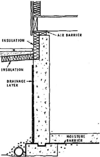
There are a number of advantages in applying insulation outside the structural elements of a wall (CBD 50). For a basement wall this will keep the concrete at a reasonably uniform temperature throughout the year and reduce the possibility of condensation on the inside surface. The below-grade portion of the wall can be insulated either by continuing the insulation down to the required depth or by placing the same amount of insulation on or just under the ground surface and extending it out from the wall, as illustrated in Figure 2. The latter is the preferred location because it maintains the soil adjacent to the basement wall above freezing, thus promoting drainage through the soil; and avoids the possibility of frost heave damage that exists with insulation fixed to the wall below grade. Insulation selected for this purpose must be resistant to moisture (for example, extruded polystyrene) and for the above-ground portion must be protected from solar radiation and physical damage. Stucco, paint or asbestos cement sheets have been used on walls for this purpose, with crushed stone, patio slabs or soil employed to protect insulation placed on the ground.
Figure 2. Exterior insulation of basement wall.
Placing the insulation on the outside can simplify the interior finishing of basement walls. If adequate control of water at the exterior has been provided, the interior can be left plain or, for aesthetic effect, painted or wallpapered. Panelling can be installed on furring strips, leaving a ventilated space behind the panels. If insulation must be placed on the inside, it should be protected from moisture or be inherently moisture resistant. Batt-type insulation must be protected by a vapour barrier and the below-grade portion by a moisture barrier (CBD 13). Insulation on the inside should be installed tightly against the concrete to reduce the possibility of air circulation, which could lead to condensation. Walls constructed of hollow masonry units should be insulated to the floor to overcome the effect of convection currents in the core spaces.
Heat is also lost from a building as a result of air leakage into the basement. The pressure differences that exist between the inside and outside of heated buildings promote air infiltration through cracks or openings at the lower levels. This cold air picks up heat, rises and
subsequently escapes from the upper levels. The caulking of joints and the use of
weatherstripping around window units greatly reduces air infiltration and thus heat loss. The most vulnerable part is usually the joint between the foundation and the superstructure, particularly in wood frame buildings. Thus, an essential part of controlling heat loss from basements is the prevention of air infiltration.
The requirements of heat loss control can be summarized as follows: 1. Caulk the joint between sill and foundation and around window frames. 2. Weatherstrip basement windows.
4. Insulate the basement wall, preferably on the outside.
Many basement walls that do not conform to these recommendations are performing well and may continue to do so. It would be very difficult, however, to guarantee that even these basements will always perform satisfactorily under unusually severe conditions simply because of their past records. In the meantime, the incidence of dampness, musty smells, rotting wood and flooding in basements is so high and the consequences so unpleasant that every effort should be made to construct a basement that will be trouble free.
Finally, it should be pointed out that not all dampness is due to improper design or
construction. Ventilation of basements during hot, humid weather, particularly in late spring and early summer, often leads to condensation on cool wall and floor surfaces. The solution is to limit ventilation during such weather and to dehumidify under particularly severe conditions.