A Comparison of Ground Source Heat Pumps and Micro-Combined Heat and Power
as Residential Greenhouse Gas Reduction Strategies
by
Brittany Guyer
Submitted to the Department of Mechanical Engineering in Partial Fulfillment of the Requirements for the
Degree of MASSACHUSETTS INSTTUTE
OF TECHNOLOGY
Bachelor of Science
at the
SEP 1 6 2009
Massachusetts Institute of Technology L R , RIS
3une 2009
ARCHIVES
© 2009 Brittany Guyer
All rights reserved
The author hereby grants to MIT permission to reproduce and to
distribute publicly paper and electronic copies of this thesis document in whole or in part in any medium now known or hereafter created.
S ignature of A uthor ... ... ... . .... .... ... . ... ... ..
Departm t of Mechanical Engineering
May 11, 2009
Certified by ...
Professor Ernest G. Cravalho Professor of Mechanical Engineering Van Buren N. Hansford Faculty Fellow Thesis Supervisor
Accepted by ... ... ... .. ...
Professor J. Lienhard V
essor of Mechanical Engineering
Table of Contents
Abstract Page 3
1. Literature Review 3
1.1 Ground Source Heat Pumps 3
1.2 Micro-Combined Heat and Power (Micro-CHP) 4
2. Electric Power Data Collection 5
3. Conventional Home Energy Systems 7
4. Ground Source Heat Pump Model 8
5. Micro-CHP Model 11
6. House Model 13
7. Carbon Comparison Calculations 15
7.1 Carbon Produced by Conventional Home 15
7.2 Carbon Produced by GSHP Home 16
7.3 Carbon Produced by Micro-CHP Home 16
7.4 Electric Grid Carbon Characteristic: Impact on Analysis 17
8. Results and Conclusions 19
8.1 Results Using Average CO2 Emissions Rate for Local 20
Grid Electricity
8.2 Results Using Fossil Fuel Generation CO2 Emissions Rate 24
For Local Grid Electricity
References 27
Appendix A: Micro-CHP and GSHP Annual CO2 Emission Comparison 29
by State
Appendix B: Table of CO2 Emissions by City for Grid Average and Fossil 40
Fuel Plant Emission Rates
Appendix C: Micro-CHP Total Carbon Profile Data 41
Appendix D: GSHP Total Carbon Profile Data 42
Appendix E: Conventional System Total Carbon Profile Data 43
Abstract
Both ground source heat pumps operating on electricity and micro-combined heat and power systems operating on fossil fuels offer potential for the reduction of green house gas emissions in comparison to the conventional approaches for providing heating, air conditioning and electric power to residential homes. Factors that may impact the relative merits are actual system operating efficiencies, regional primary energy sources for electric power generation, actual space conditioning and electric demands as well as regional climate factors. The purpose of this study is to make a consistent, realistic comparison of these greenhouse gas reduction strategies as applied to typical single-family residential homes across the United States. The study identifies both the regional variations and specific magnitudes of reductions that could be expected with these technologies when implemented within the current energy infrastructure. These comparisons are achieved by identifying the performance characteristics of both technologies, developing typical application scenarios and collecting important regional data associated with electric power production and climate variations. The results show that indeed regional variations exist in the relative merits of micro-CHP systems and ground source heat pumps on reducing the carbon emissions for households. Specific results are sensitive to the assumptions made regarding the carbon production characteristics of incremental increases or decreases of electrical demand on the local electricity utility grid.
1.
Literature Review
1.1 Ground Source Heat Pumps
Ground source heat pumps are a readily available commercial technology. Currently the world leaders in ground source heat pump (GSHP) installations are the USA, Sweden, Germany, Canada and Switzerland. Installations are available in a variety of forms, mostly dependent upon the terrain surrounding the site of application. Lund et al. [1] summarized the various options for GSHP installation as well as the technology's current status in the countries in which it is most frequently installed. With regard to the environmental impact of GSHP technology, Lund et al. argue for increased production of renewable electricity on the electric grid as this would make GSHP 100% renewable. They calculate the amount of less carbon produced by not using fossil
fuels to heat homes, but do not make any attempt to address the carbon production that results from the production of grid electricity.
Hanova et al. [2] focuses on the specific applications for which net carbon emissions will be reduced when comparing the conventional home heating methods: gas, oil and electric, to the emissions generated by the central power plant associated with the amount of electricity needed to run the GSHP. Economic analysis of GSHP is performed by examining average fuel and electric prices in various countries to determine economic payback of the system. Finally, scale effects of GSHP are examined to determine the manner in which GHG reduction and annual economic savings are associated with heat load. The accompanying equations serve as a good reference for the basic savings and emissions calculations. Although Hanova et al. address the issue of net emissions associated with GSHP, they do not go so far as to identify any regional trends arising from varying primary energy sources. Instead, they simply sets guidelines for implementation based upon average cost and emissions data.
The Energy Center of Wisconsin [3] looked specifically at various sized GSHP installations in Wisconsin and determined the reduction of GHG emissions associated with each type of installation by examining the primary fuel associated with power generation in three areas of the state. The results showed that emission reductions were achieved for large sized applications: offices and schools, but for residential applications where GSHP were used to replace conventional gas heating, there was actually an increased amount of GHG emissions associated with the GSHP installations due to the source of grid electricity largely being coal. The report also examined the economics of GSHP and showed that there was total resource energy savings associated with all classifications of installations as well as achievable payback in 10 - 25 years depending upon the sizing of the application.
1.2 Micro-Combined Heat and Power (Micro-CHP)
Unlike ground source heat pumps, micro-CHP systems have been created using a variety of technologies. Currently, systems to date include those based upon reciprocating internal combustion engines, micro turbines, Stirling engines and fuel cells. Although systems exist incorporating all of these technologies, there do no exist market ready technologies in every category.
Onovwiona et al. [4] surveys the current existing technologies that have potential to serve as options in the residential market. Systems incorporating reciprocating internal combustion engines range in size from 1kW to 10MW electric and can be operated using a variety of fuels making them applicable to a variety of residential situations. The efficiency of cogeneration
systems using reciprocating internal combustion engines ranges from 85-90%.
Micro-turbine based cogeneration systems range in size from 25-80 kW and achieve operating efficiencies of 80%. Compared to reciprocating internal combustion engines, micro-turbines typically have a smaller relative size and fewer moving parts leading to less demand for maintenance. Like reciprocating internal combustion engines, micro-turbines also have the ability to operate on a variety of fuels. These systems may be appropriate for cogeneration systems serving house communities, but are much too large for individual residences.
Fuel cell micro cogeneration systems' greatest attraction is their low emissions profile and low noise levels; however, they are still very expensive and have not yet demonstrated long lifetime. They operate at system efficiencies of up to 80% and due to their low number of moving parts, offer the potential for relatively low maintenance costs.
Micro-CHP systems based on Stirling engines are not widely implemented; however, they are currently under active development. Because the heat supply to these engines is external they offer the possibility for using a variety of primary fuels as well as reduced maintenance. Efficiencies of Stirling micro-CHP systems range from 65%-85% with electrical outputs of 1 kW to IMW.
As a means for the reduction of GHG emissions, micro-CHP has been shown to be a universally effective technology by Pehnt et al. and Peacock et al. [5,6]; however, to date there have been no known US regional comparisons conducted concerning the GHG reduction potential of GSHP versus micro-CHP.
2. Electric Power Data Collection
Since the aim of this study is to determine the regional differences associated with the carbon production resulting from the implementation of GSHP and Micro-CHP, regional electric power emissions data was collected for 100 major cities in the United States. This information facilitates assessment of the carbon production impact of the increasing electric demand on the grid, due to ground source heat pump systems and the decreasing demand on the grid resulting
from the use of micro-combined heat and power systems. City selection was done in three stages. First, the most populous city from each state was selected. Second, the 50 most populous cities in the country were selected. Naturally, there was some overlap between these two categories. The remaining cities were chosen based upon population rank within individual states as well as geographical location. So, for instance, if the second largest city was very close in proximity to the largest city within a particular state, and the third largest city was located on the other side of the state, the third largest would be selected over the second largest. Having a wider variety of geographical locations allows for a more accurate description of the
geographical variations resulting from the implementations of the technologies.
In order to determine the amount of carbon produced at central power stations per unit of electricity, data from the EPA was used. The EPA provides online accessible models that calculate the carbon emissions from electric power plants for cities across the United States [7]. The data input is in the form of a zip code and the output emission rate of CO2 is given in
lbs/MWh of produced power. The model calculates the CO2 emission rates based upon the fuel
source and corresponding plant efficiencies of the power plants in a specific region. To use the model, appropriate zip codes were collected for each city and input into the model to determine the regional CO2 output emission rate. This model provides the local grid average for carbon
emissions resulting from electric power production.
Use of the local grid average for carbon emissions has been questioned as being appropriate for determining the marginal carbon production impacts of electric conservation or electric-using technologies. The reason for this is that the total electric power demand on the grid varies daily. Therefore, the types of power generation, and their associated carbon production characteristics, used to meet incremental loads at any one time on the grid, are likely to be different from the grid average and relative carbon production average. For example, nuclear plants are carbon free and run continuously, while much of the "peaking" capacity of the grid is fossil fuel based. Some experts in the field of energy analysis have suggested that use of the local grid average fossil fuel plant carbon emission rates is the most appropriate characteristic to use when analyzing technologies that have associated incremental electrical loads (or reductions) since this more closely represents the actual change exhibited in grid power plant usage. Appendix B provides the data for these two different assumptions.
3. Conventional Home Energy Systems
In order to provide an appropriate context for the study of ground source heat pumps and micro-CHP, the conventional means for heating and cooling a home will be discussed.
In the United States, the most common means for heating a home is through the use of a warm-air furnace which uses natural gas as a fuel. For the single-family detached housing unit, which will serve as the model home type in this study, 46% use natural gas warm-air furnaces [8]. The operation of a natural gas warm-air furnace is rather simple. Natural gas is taken from the pipeline and combusted. Through means of a heat exchanger, the heat of combustion is then transferred to the circulating air, which is then driven around the house by a fan.
In order to make the comparison of a warm-air natural gas furnace to the implementation of a ground source heat pump and micro-CHP, the furnace used for comparison will be one of the high efficiency class. High efficiency furnaces can achieve efficiencies up to 97%. The efficiency of the furnace represents the total BTU heat output over the total BTU fuel input (eqn. 1).
BTUheat output
]'furnace
BTU
BTUfuel input
Since the thermal efficiency characterizes the operation of the whole system, a specific model need not be chosen. For the purposes of this study an efficiency of 95% will be used as it represents the operation of a furnace likely to be found in a high efficiency home.
Since the objective of this study is to determine a home's annual environmental impact, a conventional cooling system was selected to serve as the cooling component for a conventional home as well as a home which uses micro-CHP for heating. A conventional cooling system is not needed in the home with a ground source heat pump as the ground source heat pump provides cooling for the home in the summer.
Cooling systems are characterized by an efficiency known as the energy efficiency ratio, or EER. This ratio represents the BTU of output cooling over the kilowatt-hour of electricity input (eqn. 2); therefore the higher the EER, the greater the efficiency.
BTU
EER
= TUcooling output (2)Whelectricy input
Nationally, high efficiency air conditioners have EER values in the range of 16 to 23 [9]. For the purposes of this study an EER of 20 was chosen as it is near the top in performance within the high efficiency range. As in the selection of the natural gas furnace efficiency, it is a value that is realistically to be found in a high efficiency home.
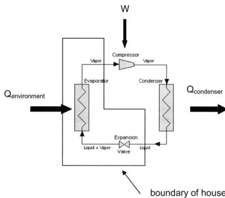
The type of air conditioning system most frequently found in homes is vapor-compression air conditioning (Fig. 1). Vapor vapor-compression air conditioning works by circulating a refrigerant through a closed cycle consisting of a compressor, condenser, throttle, and evaporator. This cycle allows for the transport of energy from the indoors into the outdoors to achieve a cooling effect.
W Compressor Vapor , por Evaporal o Condenser Qenvironment Qcondenser Expansion Liquid + apor Uq id Valve boundary of house
Figure 1. Vapor-Compression Air Conditioning Cycle
4. Ground Source Heat Pump Model
A ground source heat pump (GSHP) is a device that makes use of the earth's relatively constant ground temperature at some depth in order to heat or cool an enclosed indoor area. GSHP utilize the same cycle as conventional air conditioners: the vapor-compression
refrigeration cycle. Because GSHP are used to both heat and cool buildings, the cycle is outfitted so that the direction of heat flow can be reversed depending upon whether there is a demand for heating or cooling.
The GSHP selected for use in this study is from the Envision model line from the manufacturer WaterFurnace, which is a large player in the GSHP market. The Envision model line was chosen as it represents the highest efficiency models that WaterFurnace manufactures. The model selected for study was NS048-ECM. This model has mid-ranged air flow capacity (1500 cubic feet per minute) and represents a high-efficiency model due the use of an electrically commutated motor which is designed to operate at high efficiencies for all desired speeds.
There are a variety of implementations for GSHP. The most widely applicable is the ground loop configuration. The ground loop configuration consists of a series of tubes that lie five to ten feet below ground. Unlike some other configurations, the ground loop consists of a closed cycle and does not exchange anything with the ground but energy and entropy.
GSHP are characterized by two operating efficiencies, one for heating (COP) and one for cooling (EER). The COP is defined as the ratio of the heat out to the work in, and in this case the BTU output to the Watts input.
COP BTUheat output
COP=
-
(3)
k Whelectricity _input
The EER is the ratio of the BTU of output cooling to the input in kilowatt-hours of electricity, just as in the case of the conventional air conditioner (see eqn. 2).
In order to determine the most accurate operating conditions for each geographic location of interest, the COP and EER of the GSHP were related to the average annual ground temperature. National weather data taken from the U.S. Department of Energy's website [10] was used as it featured the monthly average 2 meter ground temperatures for a given city. These monthly averages were averaged to determine an average annual ground temperature. The 2 meter depth was appropriate as it represents a typical depth of installed tubing in ground loop
GSHP.
In order to relate ground temperature to the COP and EER, the product specification data was used to create a relationship between the temperature and efficiency. The product specification data was taken directly from the specification catalog of the product [ 11]. The data is formatted in a table relating the COP/EER to the entering water temperature. Entering water
temperature is defined as the temperature of the water (the system working fluid) as it comes out of the ground prior to its entering the vapor-compression cycle. Typically GSHP systems are designed so that the difference between the ground temperature and the entering water
temperature is no more than 8K. In this study, the assumption was made that for the winter months, the entering water temperature is 5 oF cooler than the ground temperature, and during the summer months it is 5 oF warmer than the ground temperature.
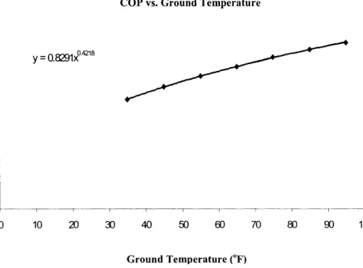
The product specification data tabulates the entering water temperature in increments of 10 OF. In order to interpolate the values between these ten degree increments, the entering water temperature was plotted against the corresponding COP and EER values in two separate graphs. For the plot of the entering water temperature versus COP, the trendline function in Excel was used to make a power function fit of the data points. Likewise, for the entering water temperature versus EER graph, a third degree polynomial function fit was used. The precision of the trendline functions was determined by eye. For each graph, multiple trendlines of differing function types were tested to see which best fit the plotted data. These two relationships are shown in figures 2 and 3 below.
COP vs. Ground Temperature
04218 5 y = 0.8291x4218 4 ©
3-2
1 0-0 10 20 30 40 50 60 70 80 90 100 Ground Temperature (F)EER vs. Ground Temperature 35 30 25 20 15 y = 3E-05 - 0.0O + 0.1131x + 29.968 10 5 0 I I I I 0 10 20 30 40 50 60 70 80 90
Ground Temperature (oF)
Figure 3. GSHP EER relation to ground temperature
With the ability to interpolate between the ten degree increments, for any given average
annual ground temperature a specific COP and EER can be defined. Since the COP and EER describe the overall operating performance: the energy output and energy input, these two values can be directly used to determine the carbon produced through the use of GSHP.
5. Micro-CHP Model
Micro-Combined Heat and Power (Micro-CHP) is a space heating technology that simultaneously produces heating and electricity in residential homes. The type of micro-CHP selected for analysis in this study uses internal combustion engine technology to produce heat and power. The company ECR International markets this product under the name freewatt [12].
Freewatt operates by exclusively using natural gas to run an internal combustion engine
operating on a 4-stroke Otto cycle. This, in turn, drives an electrical generator. The heat of combustion that is not transferred into work is captured and through means of a heat exchanger, is circulated throughout the ductwork of the home. Due to the sizing of the Micro-CHP system, the heat generated from the internal combustion engine may not always be enough to meet the heat demand of the home. Therefore, the power generation system is paired with a high efficiency natural gas fired furnace. This auxiliary furnace operates only when the heat from the power generation unit does not meet the total demand.
Because of freewatt's two-stage operation (power generation plus auxiliary heating furnace), the determination of the precise operating characteristics is based upon multiple variables such as seasonal variation in heat demand, home size and heating intensity required. Since the goal of this report is to characterize each the heat demand of each city by its number of heating degree days, a model was needed to relate the operating characteristics of the freewatt system to the value of heating degree days for a given location. A model which related these two quantities was provided to me by the manufacturer offreewatt. This model is based upon the operating characteristics of a variety of actual system installations. Based on the data from actual installations, the model determines how much heat is derived from the power generation module and the auxiliary furnace. This then allows for an accurate prediction of this breakdown for the weather data of any city.
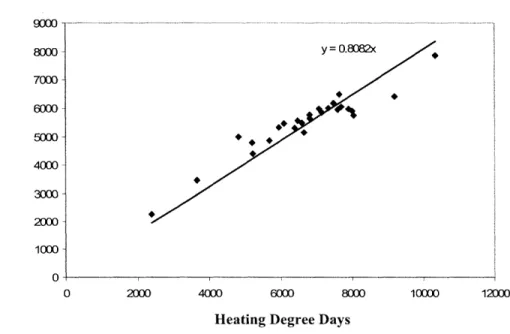
The model was used to extract operating data for 26 cities. The values derived from the model were heating degree days, electricity produced by the power generation module and the total annual gas consumption of the system (power generation plus auxiliary furnace). Two graphs were constructed from this data. Since the relationship between heating degree days and operating characteristics was desired, heating degree days was plotted against the electricity production as well as the annual gas consumption. Linear trendlines were created on both of
these plots so that general relationships could be extracted from the data (Figures 4 & 5).
Heating Degree Days vs. MCHP Electricity Production
9000 8000 y = 0.8082x 7000 6000 a 4000 S2000 1000 0 0 2000 4000 6000 8000 10000 12000
Heating Degree Days
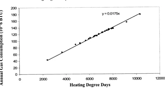
Heating Degree Days vs. MCHP Annual Gas Consumption 200 180 y = 0.0175x 160 o 140 120 100 S 80 . 60 20 0 0 2000 4000 6000 8000 10000 12000
Heating Degree Days
Figure 5. Relation of Heating Degree Days with MCHP Annual Gas Consumption
With the creation of these relationships, the amount of fuel consumed and electricity produced can be calculated for any location, as heating degree days are tabulated by city. The values of fuel and electricity consumption allow for the determination of the carbon production associated with the use of Micro-CHP.
Unlike GSHP, Micro-CHP technology only provides for heating, rather than for both heating and cooling. Therefore, a different system needs to be used to meet the cooling demands. In this study a high efficiency vapor-compression air conditioner with an EER of 20 was used. This is the same system that was used in the conventional system home model.
6. House Model
A single-family detached home was used as a model structure in this analysis. There are 72.1 million homes in this class representing the majority, or 65%, of the housing units in the United States [13]. The average home is 2,349 square feet in size and was built around 1970
[14]. This average home size and age were used in the making of this model.
In order to characterize the heating demand properly, a heating intensity required for this type of home structure was determined. For homes built around the year 1970, the design characteristic for this model, a heating intensity of 5.6 BTU/HDD*sq-ft is required [15], where HDD represents annual heating degree days and sq-ft is the total heated square feet. Heating
degree days are a way to define the demand of heat. The amount of heating degrees in a single day is determined by the difference between the standard reference value of 650F and the average
daily temperature. For the number of annual heating degree days, the heating degrees of all days are summed.
The cooling intensity was determined in a slightly different way. The only cooling intensity discovered in literature was expressed in the units of kWh/CDD*sq-ft [16]. To convert this quantity from an electrical intensity to a thermal intensity, with units of BTU/CDD*sq-ft, an assumption needed to be made concerning the performance of the average installed air conditioner found in a home in the United States. This is because the value of the cooling intensity in the literature was indeed based upon the average implementation. Based on reports from the Energy Information Administration, it was assumed that the average installed air conditioner operates with an EER of 10. A lower EER was used here compared to the one defined for the vapor-compression air conditioner (20 EER) that was used in the various models. This is because the model is supposed to represent a high-efficiency home, whereas the given data here required the use of an EER representative of the average installed system. Using this information, the thermal cooling intensity was found to be 7.8 BTU/CDD*sq-ft. This cooling intensity is higher than the heating intensity likely due to the negative effects that sun radiation has on the cooling process within the home.
Similar to heating degree days, cooling degree days are a way to characterize a home's cooling demand. Cooling degree days use a reference temperature of 650F and are defined as the difference between 65°F and the average daily temperature.
Since electricity consumption from appliances and lights and such contribute to a home's energy profile, and subsequently its carbon profile, this electricity usage must be taken into account. The average annual electric demand in residential homes to operate all devices (except electric heaters and cooling equipment) in the United States was 7989 kWh for 2001 [17], the most recent year for which data was available. This number was taken as the assumed electrical load for all uses, except heating and cooling. In order to accurately reflect the national variations in electricity usage, the electricity used for cooling is added onto the base consumption for each location.
7. Carbon Comparison Calculations
7.1 Carbon Produced by Home with Conventional Heating & Cooling System
In order to determine the amount of carbon produced by operating the previously defined conventional heating system, the annual heating load must be calculated. This is determined using the assumed heating intensity (5.6 BTU/HDD*sq-ft) the house size (2,349 sq-ft) and the number of heating degree days. Annual heating loads ranged from about 20 million BTU in the warmer climates, to 100 million BTUs in the colder climates. Once the heating load was determined, the annual gas consumption was calculated. This study assumes a conventional natural gas warm-air furnace to operate at an efficiency of 95%. To determine the annual gas consumption, the annual heating load was divided by the 95% operating efficiency. Since 117.08 lbs of CO2 are produced for every million BTU of natural gas burned, the amount of
carbon produced annually by the conventional heating system was calculated by multiplying this conversion factor by the annual gas consumption in millions of BTU. The pounds of CO2
produced annually ranged from about 2,000 lbs to 10,000 lbs for the different geographical locations.
Likewise, for the conventional cooling system, the annual cooling demand was determined by using the assumed cooling intensity (7.7 BTU/CDD*sq-ft), the home size (2,349 sq-ft) and the annual number of cooling degree days. Using the defined EER of 20, the electricity consumed by the conventional cooling system was calculated by dividing the cooling demand by the EER. The CO2 produced from operating the cooling system is directly dependent
on the power plants from which the power is sourced. Therefore, to determine the amount of CO2 produced, the annual electricity consumed by the cooling system is multiplied by an
assumed carbon output emission rate for a particular location. The amount of CO2 produced
from annual domestic cooling ranged from as low as about 100 lbs per year to as high as about 6000 lbs per year, depending on the location and carbon emission characteristic of the local grid supplied electricity.
The CO2 produced for the general appliance electric consumption was calculated in
exactly the same way as the CO2 produced as a result of electricity use of the cooling system.
Therefore, for the assumed annual amount of electricity consumed (7989 kWh), the amount of CO2produced ranged from 7,000 to 16,000 lbs.
To determine the annual carbon footprint of a home with a conventional heating and cooling system, the CO2 produced by the heating and cooling system and the annual general
appliance electric consumption were summed. These values ranged from about 10,000 lbs to 30,000 lbs.
7.2 Carbon Produced by GSHP Home
As discussed previously in the explanation of the GSHP model, the heating COP and cooling EER of the GSHP in each location were determined based on a relationship formed with the average annual ground temperature. To determine the annual electricity required for the GSHP in heating mode, the annual heat demand was divided by the heating COP. The calculation of the annual heat demand remains the same as for the conventional heating system, as described above, as it is dependent on only the weather and house model which remain the same throughout the investigation of all of the technologies. To find the amount of CO2 produced
by GSHP in heating mode, the electricity consumed is converted to lbs of CO2 via the grid
supplied electric power carbon emission output rate as described earlier.
The calculation of the CO2 produced by the GSHP in cooling mode is nearly identical to
that of the heating mode. To determine the annual electricity consumption for cooling, the annual cooling demand was divided by the EER. This annual electricity demand was then converted in pounds of CO2 via the emission output rate for each city.
The CO2 produced from the operation of the GSHP in heating and cooling modes was
added to the CO2 produced by the general electric appliance consumption to determine the
annual carbon footprint. The calculation for the CO2 from the general appliance electric
consumption remains unchanged from the analysis of the conventional system. The total annual carbon footprints ranged from under 10,000 lbs of CO2 to over 30,000 lbs of CO2 for the model
home with a ground source heat pump used for heating and cooling.
7.3 Carbon Produced by Micro-CHP Home
Based upon the results of the model constructed for the micro-CHP system, the annual electricity production and natural gas consumption for each location were determined. Using the conversion factor of 117.08 lbs of CO2 per 1 million BTU natural gas, the amount of CO2
Since this study pairs the micro-CHP system with a conventional air conditioning system, the carbon produced by the operation of the air conditioning is calculated exactly the same way as described earlier in the section on the conventional energy systems.
The micro-CHP produces a substantial amount of useful electricity, ranging from 1000 kWh to 6000 kWh annually, this must be taken to account when considering the amount of
electricity required from the grid. In order to account for this, the amount of electricity generated by the Micro-CHP was subtracted from the pre-determined general appliance annual demand. The CO2 associated with this net electric intake is calculated by multiplying it by an
appropriate CO2 output emission rate for grid supplied electricity.
7.4 Electric Grid Carbon Characteristic: Impact on Analysis
As the discussion above regarding the calculation of the total carbon emissions profile for the three technology alternatives (conventional, GSHP, micro-CHP) indicates, the results of their comparative performance depends on the assumed carbon characteristic of the grid electricity. In performing these analyses, it became clear that this specific value assumed for this carbon characteristic would significantly influence the comparative performance of these technology alternatives with regard to their impact on carbon emissions. Simply stated, a low assumed grid electricity carbon characteristic favors the use of a ground source heat pump as a carbon reduction strategy, while assumption of relatively high carbon production characteristics of the grid favors the micro-CHP alternative, as it displaces (rather than increases) carbon intensive electric power production. The net carbon production characteristic of micro-CHP system generate electricity itself is low, even though it operates on natural gas fossil fuel. This is because its efficiency in use of natural gas is effectively 90%, as it produces electric power on top of the already in-place consumption of gas for heating.
Compared to the determination of the heating and cooling loads and the power consumption of these demands, which is rather straightforward, the basis for making a reasonable assessment of the grid carbon characteristic is not clear and appears to be a debatable subject. Does one assume that all electric conservation (or use) technologies add to the incremental reduction (or use) of fossil fuels where all low carbon producing power stations will always be used as a priority? Or does one assume that the average is just that, the average, and nothing more can be reasonably assumed?
To address this issue, two different assumptions of grid electric carbon profiles have been assumed for the displaced electricity generated by micro-CHP and the increased electricity used by GSHP. These are
1) Local Grid average provided by Environmental Protection Agency
2) Local Grid Fossil Characteristic as provided by The Emissions & Generation Resource Integrated Database
The different specific values for the different geographical areas are provided in Appendix B.
The local grid average electricity emission profile takes into account all types of electric production: coal, gas, oil, nuclear, renewables etc., as present in the local area. The average is computed from the total generation contributed by each type of plant. An alternative method of assessing the impact of power conservation measures on carbon emissions from grid electricity production is to assume that all conservation (or increased usage) results in the offset (or increase) of the use of fossil fuel generation. The rationale for this is that if carbon reduction is a primary driver for conservation, then it is the reduction of the fossil fuel use that will be achieved. Other types of low carbon generation would continue, such as hydroelectric, nuclear and renewables. Personal correspondence with one energy analyst, Bruce Hedman, active on the national level with regard to combined heat and power has suggested that this alternative method is the most rational basis for assessing impacts involving use of combined heat and power on total carbon emissions [18]. Applying the above rationale to GSHP would imply that the additional electric demand generated from the use of GSHP would be met by increasing the use of fossil fuel plants. This is largely due to the relative ease at which the output of fossil fuel plants can be scaled. At this current point in time it may be reasonable to assume that any increased grid electric demand from the increased use of GSHP would be met by electricity produced by fossil fuel plants.
The method used to determine the annual CO2 generation for homes with micro-CHP
using the fossil fuel emission rate for the local grid electricity only slightly differs from the method used to determine the same output using grid average data. The method differs in the way the annual CO2 production associated with electric generation is calculated. First the
average CO2 emission rate for the specific geographical region. This assumes the electricity
taken from the grid for appliance use resembles the local grid average emission profile. Second, the electricity produced by the micro-CHP (or the displaced electricity) is multiplied by the local fossil fuel CO2 emission rate [19]. Finally, these CO2 emissions savings associated with the
displaced electricity is subtracted from the CO2 associated with the annual average electric
consumption. The result is the net CO2 generation associated with the model home's annual
appliance electric consumption. To determine the total annual CO2 produced by homes with
micro-CHP, the CO2 production associated with the use of natural gas in the micro-CHP system
and the electricity use associated with appliance use and cooling are summed.
The method used to determine the annual CO2 generation for homes with GSHP uses the
local grid fossil fuel emission rate to calculate the CO2 generated as a result of the GSHPs use of
electricity to meet the heating and cooling requirements. To calculate the GSHPs annual CO2
generation, the annual electricity required for running the GSHP in heating and cooling mode is multiplied by the local fossil fuel CO2 emission rate to determine the CO2 associated with heating
and cooling. The CO2 emissions associated with the electricity used for appliances are
determined by multiplying the annual appliance electric use by the local grid average CO2
emission rate. The local grid average emission rate is used in this case because the annual appliance electric use does not represent part of the increased demand of electricity due to the use of GSHP. To determine the annual CO2 generated for the model home with GSHP, the CO2
generation associated with heating and cooling is added to the CO2 generation associated from
appliance electric use.
8. Results and Conclusions
In this study an attempt has been made to resolve the actual relative merits of GSHP and micro-CHP systems in lowering the carbon foot print of the typical America home. If one
assumes electricity is available from carbon-free sources such as nuclear power, wind, hydro power, or the sun, then the answer is obvious. GSHP can have near zero net carbon
emissions. In contrast, micro-CHP systems run on natural gas and thus inevitably produce some level of carbon emission as this carbon based fuel is burned. Thus, with zero carbon electricity available, the clear advantage goes to the ground source heat pump.
The reality, however, is not that simple. The great majority of electricity in the United States is generated using fossil fuels. Indeed, about half is generated using coal, which is the carbon emissions intensive source of electric energy. Thus, sorting out the comparison of the "real" relative merits of GSHP and micro-CHP sources is ultimately based on the assumption of how electricity is produced by the utility grid. GSHP substantially increase electricity use from the grid while micro-CHP systems substantially reduce it. Relative merits depend on assessing the carbon emission characteristics of locally obtained electricity.
In this study it has been possible to characterize well the thermal and energy performance of a model home in different locations in the United States with conventional, GSHP, and micro-CHP energy systems. What has been more difficult is to characterize the carbon characteristic of the locally supplied electricity from the grid that is part of net carbon emission
calculation. The grid electricity carbon characteristic is critical to the results of the comparison of these home energy systems. Determining exactly how much carbon emissions is saved for each kilowatt-hour reduction in electric use was found to be an open and debatable question in the field of energy and environmental analysis. So what has been done here has been to look at several different reasonable assumptions regarding the relationship between grid electric power production and carbon emissions. The particular cases of interest are 1) the local average carbon emissions for electric power from the grid and 2) the local average of fossil fuel electric generation. Both of these characterizations have been reported by government agencies for use in assessing electric power and carbon emissions issues.
The first assumption is the most simple. It is the simple average of all power generation. The second is applied as it is more relevant to the idea that a national carbon reduction strategy may be based on reducing fossil-carbon-based electric generation, not electric
generation itself. Thus, both assumptions have merit. It depends on the perspective.
8.1 Results Using Average C0 2 Emissions Rate for Local Grid Electricity
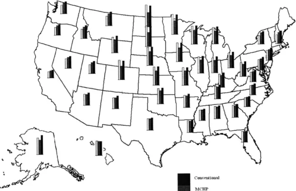
The results for the assumption of local grid average carbon emissions for all electric savings (and increases) are depicted in graphical forms in a series of maps. The first (Fig. 6) shows the state averages of the relative magnitudes of the annual CO2 generated for the
Conventional
Figure 6. Comparative energy-related CO2 emissions for model home for GSHP,
micro-CHP and conventional systems by state using local grid average CO2
emission rates
Figure 6 is useful in determining the relative impact of each technology as implemented in a particular state. In nearly all cases it is evident that GSHP and micro-CHP produce less CO2 than
the conventional system; however there are some exceptions. In the north Midwest, the CO2
produced by GSHP exceeds that produced by the conventional system, highlighting the dramatic impact carbon intensive fossil fuel based electric generation has on the merits of GSHP.
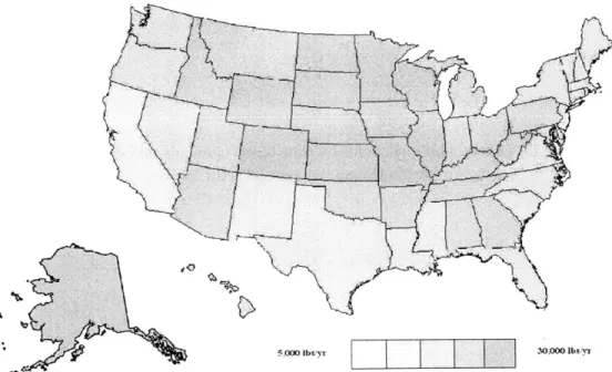
In order to visualize the trends of CO2 intensity among each technology, two graphics
5,000 lbs yi 30,000O lbsyr
Figure 7. Total annual energy-related CO2 for Model homes with GSHP using
local grid average CO2 emission rates
10,000 Ibs i 20.000 lbsyr
Figure 8. Total annual energy-related CO2 for Model homes with micro-CHP
The darker areas depict more CO2 intensive areas, while the lighter areas depict less CO2
intensive areas. The geographical color trends for both technologies tend to follow the same pattern. This is largely due to the inherent carbon characteristics of the local electric grid. The
Midwest, with its strong reliance on fossil fuel based electric generation, shows a more CO2
intensive profile.
However useful the trends in CO2 generation for both technologies are, the more
interesting result comes from the direct comparison of the technology on a state by state basis. This approach answers the question of which technology is better implemented in each state based upon its CO2 generation profile. In order to depict this graphically, GSHP and micro-CHP
were directly compared to the carbon profile of the conventional system. This was done in each state by taking the CO2 generated by the conventional system and subtracting the CO2 generated
by the GSHP in one case and subtracting the CO2 generated by the micro-CHP in the other case.
The resulting values represent the differences in CO2 generation for each technology as
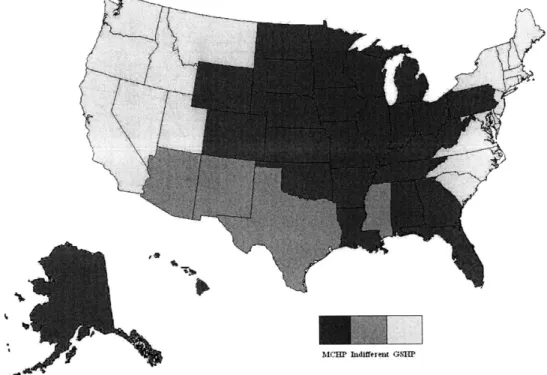
compared to the conventional system in a particular state. In order to determine which technology is better suited for a given state, a ratio of the GSHP difference to the micro-CHP difference was made. A ratio of 1:1 indicates indifference in technology preference. In this case a ratio greater than one indicates a preference to GSHP while a ratio less than one indicate preference to micro-CHP. A graphic depicting the resulting trends in ratios is shown in Fig. 9.
-McHP Indifferent GSrp
Figure 9. Best technology choice by state based upon annual CO2 emissions using grid average emissions analysis for Micro-CHP
Figure 9 indicates a preference to micro-CHP in the middle of the country, a preference to GSHP on the coast, and some indifference in the south. The high concentration of fossil fuel power generation in the Midwest favors the implementation of MCHP while the lower carbon intensive coastal regions favor GSHP. As an aside, the portrayal of micro-CHP better suited for Hawaii is somewhat incorrect. Hawaii has an annual heating demand of 0 BTU. Thus, the annual CO2
generated by micro-CHP and the conventional energy system are equal since there is no heating. However, because the CO2 generated by GSHP in Hawaii was greater than
conventional/CHP it is better suited for the conventional/CHP option for the purposes of figure 9. In reality, a micro-CHP system would never be utilized as there is zero demand for heat.
8.2 Results Using Fossil Fuel Generation CO2 Emissions Rate of Local Grid
Electricity
The results for analysis using the fossil fuel plant CO2 emission approach are shown
graphically in the same series of maps as used above. Figure 10 shows the relative CO2
generation of GSHP, micro-CHP and the conventional system implemented in the model home.
( olventi onlI
Axe MICHP
GSHP
Figure 10. Comparative energy-related CO2 emissions for model home for GSHP, micro-CHP and conventional systems by state using local fossil fuel plant
The most noticeable difference between fig. 10 and fig 6. is that the CO2 generated by GSHP
implementation exceeds that of the conventional system in many instances, while the CO2
generated by micro-CHP implementation is typically far less than the conventional system. The trends in GSHP and micro-CHP are portrayed in figures 11 and 12.
S10,000 l br 20,000 Ibs'yr y
Figure 11. Total annual energy-related CO2 for model homes with micro-CHP
using local fossil fuel plant CO2 emission rates
5.000 lbs yr -i0 3 0lbs r
Figure 12. Total annual energy-related CO2 for model homes with GSHP using
Compared to the CO2 generation trend of micro-CHP utilizing local electric grid average CO
2
emission data, fig. 11 shows micro-CHP in a much more favorable light, displaying much more pink, indicating lesser magnitudes of CO2 emissions. On the other hand, fig. 12 shows much
darker areas over most of the country, indicating that this fossil fuel CO2 emission based form of
analysis is not favorable to GSHP.
To further emphasize the favorable light that is cast on micro-CHP using this form of analysis, figure 13 depicts micro-CHP as the best-choice technology for every state.
MCHP bidiffercnt ;SBIf
Figure 13. Best technology choice by state based upon annual CO2 emissions
References
[1] Lund, J., B. Sanner, L. Rybach, R. Curtis, and G. Hellstrom. 2004. "Geothermal (Ground Source Heat Pumps) A World Overview." GHC Bulletin. pp. 1-10.
[2] Hanova, J., and H. Dowlatabadi. 2007. "Strategic GHG reduction through the use of ground source heat pump technology." Environmental Research Letters. pp. 1-8.
[3] Energy Center of Wisconsin. 2000. "Emissions and Economic Analysis of Ground Source Heat Pumps in Wisconsin." pp. 1-68.
[4] Onovwiona, H. I., and V. I. Ugursal. 2004. "Residential cogeneration systems: review of the current technology." Renewable and Sustainable Energy Reviews. 10 pp. 389-431.
[5] Pehnt, Martin. 2008. "Environmental impacts of distributed energy systems -the case for micro-CHP." Environmental Science and Policy. 11 pp. 25-37.
[6] Peacock, A. D., and M. Newborough. 2005. "Impact of micro-CHP systems on domestic sector CO2 emissions." Applied Thermal Engineering 25 pp. 2653-2676.
[7] "How clean is the electricity I use?" U.S. Environmental Protection Agency. <http://www.epa.gov/cleanenergy/energy-and-you/how-clean.html>.
[8] "2005 Residential Energy Consumption Survey."Apr. 2008. Energy Information
Administration.<http://www.eia.doe.gov/emeu/recs/recs20 05/hc2 0 0O55-tables/hc4spacehea ting/pdf/tablehc2.4.pdf>.
[9] "High-efficiency 16 to 23 SEER Central Air Conditioner Review." Product Reviews and Reports -ConsumerSearch.com.
<http://www.consumersearch.com/central-air-conditioners/high-efficiency- 16-23-seer-central-air-conditioner>.
[10] "EnergyPlus: Weather Data." U.S. DOE Energy Efficiency and Renewable Energy (EERE). <http://apps 1.eere.energy.gov/buildings/energyplus/cfm/weather data3.cfm/region=4no rthandcentral america wmo region_4/country=1 usa/cname=USA>.
[ 11] WaterFurnace. Envision Residential Specification Catalog.
<http://secure.waterfumrnace.com/docs/FB507406666/manuals/envision/SP 1585.pdf>. [12] Freewatt Eco-Friendly Heating & Power Systems. 20 Jan. 2009 <http://freewatt.com>.
[131 "Housing Unit Characteristics by Type of Housing Unit." Energy Information Agency. <http://www.eia.doe.gov/emeu/recs/recs2005/hc2005 tables/hc housingunit/pdf/tablehc
[14] Adler, Margot. "Behind the Ever-Expanding American Dream House : NPR." NPR. <http://www.npr.org/templates/story/story.php?storyld=5525283>.
[15] Comprehensive Energy Use Database.
<http://oee.nrcan.gc.ca/corporate/statistics/neud/dpa/trendsres_on.cfm>.
[16] "Electric Air-Conditioning Energy Consumption in U.S. Households by Type of Housing Unit." 2001. Energy Information Agency.
<http://www.eia.doe.gov/emeu/recs/recs2001/ce df/aircondition/ce3-4c_housingunits2001 .pdf>.
[17] "U.S. Household Electricity Data: A/C, Heating, Appliances 2001." Official Energy Statistics from the U.S. Government. Energy Information Agency.
<http://www.eia.doe.gov/emeu/reps/enduse/er01 us tab .html>.
[18] "Discussion of Fossil Fuel Replacement Approach to Carbon Emissions Reductions." E-mail interview. 3 Apr. 2009.
Appendices
Appendix A: Micro-CHP and GSHP Annual CO2 Emission Comparison by State
Note: Magnitudes of emissions may not be compared between figures, only within the figure itself
RED: Annual micro-CHP CO
2emissions
Annual GSHP CO
2emissions
Appendix A.1: Relative magnitudes of GSHP and micro-CHP CO2 emissions
Appendix A.2: Relative magnitudes of GSHP and micro-CHP CO2 emissions
Grand Rapids, MI Madison, WI
IN
Columbus,
Appendix A.3: Relative magnitudes of GSHP and micro-CHP CO2 emissions
in cities in Wisconsin, Michigan, Illinois, Indiana, Ohio, Kentucky and West
Virginia
Springfield,
Appendix A.4: Relative magnitudes of GSHP and micro-CHP CO2 emissions
in cities in Wyoming and Colorado
Jackson, MS
Charleston, SC
Gulfport, MS
Mia i, FL
Appendix A.5: Relative magnitudes of GSHP and micro-CHP CO2 emissions
Appendix A.6: Relative magnitudes of GSHP and micro-CHP CO2 emissions
Appendix A.7: Relative magnitudes of GSHP and micro-CHP CO2 emissions
Appendix A.8: Relative magnitudes of GSHP and micro-CHP CO2 emissions
in cities in Maine, New Hampshire, Vermont, Massachusetts, Rhode Island, Connecticut, New York, New Jersey and Pennsylvania
Appendix A.9: Relative magnitudes of GSHP and micro-CHP CO2 emissions
Smith,
j
le Rock,New
Appendix A.10: Relative magnitudes of GSHP and micro-CHP CO2
emissions in cities in Oklahoma, Arkansas and Louisiana
Appendix A.11: Relative magnitudes of GSHP and micro-CHP CO2
ginia Beach, VA
Nashville, TN Raleigh, NC
Appendix A.12: Relative magnitudes of GSHP and micro-CHP CO2
Appendix B: CO2emissions by city for grid average and fossil fuel plant emission rates City Birmingham, AL Montgomery, AL Anchorage, AK Flagstaff, AZ Phoenix, AZ Tucson. AZ Fort Smith, AR Little Rock, AR Fresno, CA Long Beach, CA Los Angeles, CA Sacremento. CA San Diego, CA San Franciso. CA San Jose, CA Colorado Springs, C( Denver, CO Bridgeport, CT Washington DC Wilmington, DE Jacksonville, FL Miami, FL Atlanta, GA Augusta, GA Honolulu, HI Boise, ID Idaho Falls, ID Chicago, IL Springfield, IL Fort Wayne, IN Indiannapolis, IN Waterloo, IA Des Moines. IA Topeka, KS Witchita, KS Lexington, KY Louisville, KY New Orleans, LA Shreveport, LA Portland, ME Baltimore, MD Boston, MA Worcester, MA Detroit, MI Grand Rapids. MI Minneapolis, MN Rochester, MN Gulfport, MS Jackson, MS Kansas City, MO St. Louis, MO Billings, MT Missoula, MT Lincoln, NE Omaha, NE Las Vegas, NV Reno, NV Manchester. NH Newark, NJ Albuquerque. NM Albany, NY Buffalo, NY New York, NY Charlotte, NC Raleigh, NC Bismarck, ND Fargo, ND Cleveland, OH Columbus, OH Oklahoma City, OK Tulsa, OK Portland, OR Salem, OR Philadelphia, PA Pittsburgh, PA Providence, RI Charleston, SC Columbia, SC Rapid City, SD Sioux Falls, SD Memphis, TN Nashville, TN Austin, TX Dallas, TX El Paso, TX Fort Worth, TX Houston, TX San Antonio, TX Provo, UT Salt Lake City, UT Burlington, VT Richmond, VA Virginia Beach. VA Seattle, WA Spokane, WA Charleston, WV Parkersburg, WV Madison, WI Milwaukee, WI Casper, WY Cheyenne, WY Heating Cooling 65F Base Temp 2844 1928 2269 2238 10911 0 7322 140 1552 3508 1752 2314 3336 2022 3354 1925 2650 1671 1606 985 1245 1185 2843 1159 1507 722 3042 108 2303 587 6473 461 5505 742 5461 735 5005 2898 4940 992 1327 2596 206 4038 3095 1589 2547 1995 0 4221 5833 714 7967 269 6127 925 5558 1116 6209 748 5577 974 7415 675 6710 928 5243 1361 4791 1628 4783 1140 4514 1288 1465 2706 2167 2538 7498 252 4729 1108 5621 661 6848 387 6419 654 6801 575 8159 585 8227 474 1551 2645 2300 2316 5161 1421 4750 1475 7265 498 7931 188 6012 1187 6601 949 2601 2946 6022 329 7554 328 5034 1024 4292 1316 6888 574 6927 437 4848 1068 3218 1596 3514 1394 8968 488 9254 537 6154 613 5702 809 3695 1876 3680 1949 4792 300 4852 232 4865 1104 5278 948 5972 532 1904 2354 2598 2087 7324 661 7838 719 3227 2029 3696 1694 1737 2903 2290 2755 2678 2098 2382 2587 1434 2889 1570 2994 5907 745 5983 927 7876 396 3939 1353 3495 1422 4727 183 6835 388 4590 1055 4817 1045 7730 460 7444 450 7555 458 7255 327 Zip Code 36110 35214 99501 86004 85020 85714 72904 72210 93705 90805 90025 95823 92118 94115 95120 80917 80206 06608 20018 19810 32222 33137 30315 30909 96817 83713 83404 60617 62712 46808 46220 50703 50310 66618 67211 40502 40220 70126 71103 04107 21210 02115 01602 48205 49505 55420 55904 39503 39202 64111 63112 59102 59803 58520 68106 89110 89511 03103 07107 87112 12208 14210 10010 28215 27613 58501 58102 44116 43213 73110 74126 97214 97301 19102 15210 02906 29407 29209 57702 57106 38115 37211 78704 75218 79911 76118 77004 78224 84604 84101 05401 23228 23459 98119 99203 25311 26101 53717 53205 82630 82001
Local Grid Average
CO2 Output Emission Rate (Ibs/MWh) 1490 1490 1257 1254 1254 1254 1761 1135 879 879 879 879 879 879 879 2036 2036 909 1096 1096 1328 1328 1490 1490 1728 921 921 1556 1844 1556 1556 1814 1814 1971 1971 1495 1495 1135 1761 909 1096 909 909 1641 1641 1814 1814 1490 1135 1971 1844 921 921 1814 1814 1254 921 909 1096 1254 820 820 922 1146 1146 1814 1814 1556 1556 1761 1761 921 921 1096 1556 909 1146 1146 2036 1814 1495 1495 1421 1421 1254 1421 1421 1421 921 921 909 1146 1146 921 921 1556 1556 1859 1556 2036 921
Local Grid Fossil Fuel CO2 Output Emission Rate (Ibs/MWh) 1949 1949 1435 1743 1743 1743 1863 1642 1437 1437 1437 1437 1437 1437 1437 2162 2162 1431 1687 1687 1447 1447 1949 1949 1775 2032 2032 2030 2117 2030 2030 2350 2350 2344 2344 2126 2126 1642 1863 1431 1687 1431 1431 1765 1765 2350 2350 1949 1642 2344 2117 2032 2032 2350 2350 1743 2032 1431 1819 1743 1794 1794 1819 1913 1913 2350 2350 2030 2030 1863 1863 2032 2032 1687 2030 1431 1913 1913 2162 2350 2126 2126 1673 1673 1743 1673 1673 1673 2032 2032 1431 1913 1913 2032 2032 2030 2030 2249 2030 2032 2162