Publisher’s version / Version de l'éditeur:
Vous avez des questions? Nous pouvons vous aider. Pour communiquer directement avec un auteur, consultez la première page de la revue dans laquelle son article a été publié afin de trouver ses coordonnées. Si vous n’arrivez pas à les repérer, communiquez avec nous à PublicationsArchive-ArchivesPublications@nrc-cnrc.gc.ca.
Questions? Contact the NRC Publications Archive team at
PublicationsArchive-ArchivesPublications@nrc-cnrc.gc.ca. If you wish to email the authors directly, please see the first page of the publication for their contact information.
https://publications-cnrc.canada.ca/fra/droits
L’accès à ce site Web et l’utilisation de son contenu sont assujettis aux conditions présentées dans le site LISEZ CES CONDITIONS ATTENTIVEMENT AVANT D’UTILISER CE SITE WEB.
Fire Study (National Research Council of Canada. Division of Building Research),
1969-11
READ THESE TERMS AND CONDITIONS CAREFULLY BEFORE USING THIS WEBSITE. https://nrc-publications.canada.ca/eng/copyright
NRC Publications Archive Record / Notice des Archives des publications du CNRC :
https://nrc-publications.canada.ca/eng/view/object/?id=00ec5345-de98-4d25-84e3-94101207dd2c https://publications-cnrc.canada.ca/fra/voir/objet/?id=00ec5345-de98-4d25-84e3-94101207dd2c
NRC Publications Archive
Archives des publications du CNRC
For the publisher’s version, please access the DOI link below./ Pour consulter la version de l’éditeur, utilisez le lien DOI ci-dessous.
https://doi.org/10.4224/40001337
Access and use of this website and the material on it are subject to the Terms and Conditions set forth at
Sheet steel as a protective membrane for steel beams and columns
Stanzak, W. W.
NATIONAL RESEARCH COUNCIL O F CANADA DIVISION O F BUILDING RESEARCH
S H E E T S T E E L AS A PROTECTIVE MEMBRANE FOR S T E E L BEAMS AND COLUMNS
W. W. Stanzak
F I R E STUDY NO. 23
of t h e
DIVISION O F BUILDING RESEARCH
Ottawa
S H E E T S T E E L AS A PROTECTIVE MEMBRANE FOR S T E E L BEAMS AND COLUMNS
by
W. W. Stanzak*
A p r o t e c t i v e m e m b r a n e is a continuous l a y e r s e p a r a t i n g the m e m b e r to be p r o t e c t e d f r o m the f i r e , without coming into d i r e c t t h e r m a l contact with the m e m b e r .
This r e p o r t d e s c r i b e s the r e s u l t s of f i r e t e s t s on a s t e e l beam and two columns, protected with insulating m a t e r i a l s enclosed i n a s h e e t s t e e l m e m - b r a n e c a s e .
The p r a c t i c e of protecting s t r u c t u r e s a g a i n s t f i r e by a p r o t e c t i v e m e m - b r a n e h a s been c a r r i e d out f o r m a n y y e a r s . I t was only i n the l a t e 19501s, however, t h a t p r o t e c t i v e m a t e r i a l s other than p l a s t e r and gypsum wallboards w e r e used widely a s m e m b r a n e f i r e protection. T h i s development was due t o a m a r k e d i n c r e a s e in the number of s p o n s o r e d f i r e t e s t s c a r r i e d out by m a - t e r i a l s m a n u f a c t u r e r s .
A f i r e t e s t on a s t e e l b e a m protected with a m e m b r a n e of gypsum-sanded p l a s t e r h a s been d e s c r i b e d in DBR F i r e Study No. 19 (1). The r e s u l t s of 8 f i r e t e s t s on s t e e l column sections protected with gypsum-sanded p l a s t e r a r e given i n F i r e Study No. 2 0 (2).
The available f i r e t e s t data, a s well a s s o m e t e s t s in a s m a l l f l o o r f u r n a c e ( 3 ) c l e a r l y show t h a t t h e m o s t v i t a l c h a r a c t e r i s t i c of a p r o t e c t i v e m e m - b r a n e i s i t s ability to r e m a i n in place. This was d e m o n s t r a t e d in the s m a l l f u r n a c e by the f a c t that a 16-ga (0.0598 in. ) s t e e l s h e e t m e m b r a n e i n c r e a s e d the f i r e e n d u r a n c e t i m e of a b r i c k floor by about 2 3 p e r cent. I n s e r t i n g a lightweight m i n e r a l wool i n the a i r g a p between the s t e e l and the b r i c k r e s u l t e d i n a 220 p e r c e n t i n c r e a s e in the f i r e endurance time.
In addition to its ability to r e m a i n in place, a protective m e m b r a n e , to b e r e a l l y effective, should have a low t h e r m a l conductivity and a high t h e r m a l capacity. M a t e r i a l s displaying t h e s e p r o p e r t i e s a r e r a t h e r expensive and h a r d to find. Unfortunately, many m a t e r i a l s that a c t a s good i n s u l a t o r s d e t e r i o r a t e
s e r i o u s l y f r o m t h e effects of f i r e and b e c o m e p r e m a t u r e l y dislodged. I t h a s been difficult, t h e r e f o r e , to develop m e m b r a n e protection to i t s full potential.
Sheet s t e e l h a s not been previously c o n s i d e r e d a s a potential f i r e p r o - t e c t i v e m a t e r i a l . However, i t s ability to r e m a i n in place, and the f a c t that
i t s p r e s e n c e a s a radiation shield c a u s e s the f i r e endurance t i m e of a con- s t r u c t i o n to i n c r e a s e , suggested t h a t this possibility should b e investigated. PART I : BEAM TEST
DESCRIPTION O F SPECIMEN
Details of the t e s t s p e c i m e n a r e shown in F i g u r e 1. F i g u r e 2 shows the exposed s u r f a c e of the b e a m installed in the furnace, and F i g u r e 3 shows the unexposed s u r f a c e and hydraulic loading equipment. The i t e m n u m b e r s below c o r r e s p o n d t o the p a r t n u m b e r s in F i g u r e 1.
1. S t e e l wide-flange beam, 8 in. by 5: in by 17 lb/ft, 16 f t 0 in. long, s t e e l specification CSA G40. 12.
2. Haydite Slab, 4 by 31 by 36 in., a v e r a g e density 106 lb/ft3. 3. S t e e l plate,
$
by 18 by 36 in. tack welded to s t e e l beam.4. M i n e r a l wool insulation, 3 in. thick (Johns Manville Type 413). 5. Sheet s t e e l m e m b r a n e , b r a k e - f o r m e d f r o m 36 in. by 48 in.
galvanized 20 ga (0. 0359) s h e e t s . 6. R e f r a c t o r y insulation.
TEST METHOD
The f i r e t e s t was c a r r i e d out e s s e n t i a l l y in a c c o r d a n c e with a tentative r e v i s i o n of ASTM specification E119-61: T e s t s of Loaded B e a m s (4). A de- viation f r o m the specification was t h a t the f l o o r s l a b was l e s s than the m i n i - m u m 5-ft width specified.
F u r n a c e t e m p e r a t u r e was m e a s u r e d by nine s y m m e t r i c a l l y disposed thermocouples enclosed in a 131 16 in. 0. D. Inconel tube having 0. 035 in. wall thickness. The hot junctions of the thermocouples w e r e in c a r b o n s t e e l c a p s on the Inconel tubes and w e r e placed 12 in. below the plane of the u n d e r s i d e of the f l o o r slab. Both the individual t e m p e r a t u r e s a t nine points of the f u r - nace and the a v e r a g e of the nine thermocouples w e r e r e c o r d e d . The f u e l in- put into the f u r n a c e was controlled automatically in such a way that the a v e r a g e t e m p e r a t u r e c l o s e l y followed the p r e s c r i b e d s t a n d a r d t e m p e r a t u r e - t i m e c o r - relation.
The s t e e l t e m p e r a t u r e s w e r e m e a s u r e d by 16 c h r o m e l - a l u m e l t h e r m o - couples, peened into the b e a m a t locations shown in F i g u r e 4. T e m p e r a t u r e s w e r e m e a s u r e d a t four sections, s y m m e t r i c a l l y located along the length of the beam. One of the thermocouples was located on the bottom flange a t m i d - span, a s a hot region was expected to develop t h e r e .
The b e a m was loaded s o a s to develop the s t r e s s e s contemplated by the design. A typical loading calculation f o r a b e a m t e s t i s given in Appendix A of R e f e r e n c e 1. Load was applied by two p a i r s of hydraulic jacks, e a c h p a i r connected with a c r o s s - b e a m , 36 in. on e i t h e r s i d e of midspan.
V e r t i c a l deflections w e r e m e a s u r e d a t the c e n t r e and q u a r t e r points of the span by m e a n s of t h r e e m e a s u r i n g t a p e s connected to the floor s l a b by a m e c h a n i c a l s y s t e m . The a c c u r a c y of the m e a s u r e m e n t s i s f 0.01 in.*
OBSERVATIONS DURING FIRE TEST
The deflection due to the applied live load was 0.75 in. This was c l o s e enough to the calculated t h e o r e t i c a l deflection of 0.775 in. to indicate t h a t the r e q u i r e d l i v e load was being c a r r i e d by the beam.
0 rnin
-
f i r e on10 rnin
-
s h e e t m e t a l protection s t a r t e d bulging w e s t of the c e n t r e of the beam15 rnin
-
thermocouple No. 11 on the s t e e l b e a m n e a r the bulge r e g i s t e r e d higher readings than corresponding t h e r m o - couples a t other stations90 rnin
-
b e a m bowed evenly downward without l a t e r a l deformation. P r o t e c t i o n s t i l l in place and without gaps, but warped in places.97 rnin
-
explosive spalling a t c e n t r e of c o n c r e t e s l a b on the north s i d e103 rnin
-
t e s t t e r m i n a t e d due to e x c e s s i v e deflection of the beam; f i r e out and load removed.RESULTS
The t e m p e r a t u r e r i s e c u r v e f o r the beam is given i n F i g u r e 5 and the deflection c u r v e i n F i g u r e
6.
In o r d e r that f i r e t e s t s might be t e r m i n a t e d p r i o r to, but reasonably c l o s e t o ultimate collapse, Robertson and Ryan (5) proposed that the point
*
In b e a m t e s t s in which the deflection w i r e i s attached to the floor slab, de- flection r e a d i n g s m a y be e r r a t i c during e a r l y portions of the f i r e exposure. Warping of the floor s l a b o r f a i l u r e of the s l a b t o follow the deflection of the b e a m a r e r e s p o n s i b l e f o r this. Deflections during the final s t a g e s of the f i r e t e s t a r e , however, usually quite r e l i a b l e , b e c a u s e by this t i m e the s l a b h a s weakened sufficiently t o follow the deflection of the beam closely.a t which both 6
-
ra
800
'"
d and 6 ; 2 150 d c a n be r e g a r d e d a s a n indication Cof load f a i l u r e . In t h e s e e x p r e s s i o n s 6 = c e n t r a l deflection, in. ; 6 ; = r a t e C
of deflection, in. / h r ; A = c l e a r span of p r i n c i p a l s t r u c t u r a l element, i n . , and d = d i s t a n c e between the upper and lower e x t r e m e f i b r e s of the p r i n c i p a l s t r u c - t u r a l element, in. The c r i t i c a l r a t e of deflection was not exceeded during the f i r e t e s t , although the deflection was l a r g e . T h e r e f o r e , no load f a i l u r e oc- c u r r e d according to the Robertson/Ryan c r i t e r i a .
When the t e s t was t e r m i n a t e d (103 m i n ) the b e a m had a l a r g e c e n t r a l deflection and could obviously no longer p e r f o r m i t s s t r u c t u r a l function. The f i r e endurance t i m e of t h e s p e c i m e n may, t h e r e f o r e , b e a s s i g n e d a t 103 ~ n i n .
The f i r e r e s i s t a n c e classification i s I + h r . CONCLUSIONS
1. The f i r e endurance t i m e of the s p e c i m e n was 103 m i n providing a f i r e r e s i s t a n c e classification of 1$ h r .
2. The a v e r a g e t e m p e r a t u r e on the lower flange of the b e a m was 1 2 7 0 ° F when the t e s t was t e r m i n a t e d . This i s about 100" higher than the c r i t i c a l t e m p e r a t u r e f o r non-composite b e a m s of ASTM A-36 s t e e l ( 6 ) . However, 1270" F should not be r e g a r d e d a s the c r i t i c a l t e m p e r a t u r e f o r non-
c o m p o s i t e b e a m s of CSA G40. 12 s t e e l , as load f a i l u r e according to the R o b e r t s o n Ryan c r i t e r i a had not o c c u r r e d when the t e s t was t e r m i n a t e d .
-
3. A s i m i l a r l y c o n s t r u c t e d s p e c i m e n having a b e a m of A-36 s t e e l wouldf a i l a t about 75 m i n ( a s s u m i n g a c r i t i c a l t e m p e r a t u r e of 1 1 7 0 ° F ) and r e - c e i v e a f i r e r e s i s t a n c e rating of 1 h r . T h e r e f o r e a b e a m (CSA G40. 12) having s u p e r i o r c r e e p p r o p e r t i e s yields a substantial i n c r e a s e in f i r e endurance time.
COMMENTS
The f i r e t e s t c l e a r l y d e m o n s t r a t e d that the concept of a s h e e t s t e e l p r o t e c t i v e m e m b r a n e f o r wide-flange b e a m s is valid. Although t h e p r e s e n t t e s t yielded a f i r e endurance t i m e of only I $ hr, i t should b e p o s s i b l e to de- velop a n economical f o r m of protection capable of providing a 2-hr f i r e r e - s i s t a n c e using the s h e e t s t e e l m e m b r a n e .
This was the f i r s t t e s t on a CSA G40. 12 b e a m to be conducted a t this l a b o r a t o r y . The s u p e r i o r c r e e p p r o p e r t i e s of the CSA G40. 12 s t e e l give the b e a m excellent f i r e enduring qualities.
PART
II:
COLUMN TESTSThis portion of the r e p o r t d e s c r i b e s two f i r e t e s t s conducted on s t e e l column sections protected with insulating m a t e r i a l s enclosed by a s h e e t m e t a l m e m b r a n e . The insulating m a t e r i a l s w e r e chosen, not only f o r t h e i r economy, but b e c a u s e they a r e not p r o p r i e t a r y products.
T h e t e s t s w e r e c a r r i e d out in the DBR floor f u r n a c e and the s p e c i m e n s w e r e not loaded.
DESCRIPTION O F TEST SPECIMENS
Construction d e t a i l s of a typical t e s t s p e c i m e n a r e shown in F i g u r e 7. The i t e m n u m b e r s below c o r r e s p o n d to the p a r t n u m b e r s in the figure.
Specimen No. 1.
1. Wide-flange s t e e l column section: 10 WF 112, 8 f t 4 in. long, S t e e l Specification ASTM A36-61 T.
2. I-in. M e s h Chicken Wire (0. 028 in. d i a m e t e r ) , galvanized. 3 . M i n e r a l Wool Building Jhsulation
( a ) Conforms to CSA Standard A 101 (7), Type 1A. ( b ) Dimensions: 3 by 23 by 48 in.
( c ) Composition: M i n e r a l wool f i b e r s produced f r o m b l a s t f u r n a c e slag.
( d ) Mechanical and P h y s i c a l P r o p e r t i e s :
Resilience: r e t u r n s t o r e f e r e n c e thickness a f t e r r e l e a s e . Weight: 3.6 l b p e r batt.
Density: 1 . 9 lb p e r cubic foot.
Btu/in. T h e r m a l conductivity (in oven-dry condition a t 7 5 ° F ) : 0.28
1 ( h r ) ( f P
I("
F
4. Standard Gypsum wallboard, ,-in. thick.
5. 26 qa (0. 0217) wiped zinc galvanized sheet s t e e l .
6. # 8 Sheet M e t a l Screw, 318 in. long a t 8-in. 0. C. The outside dimensions w e r e 1 8 by 18 in.
Specimen No. 2
1. Wide-flange s t e e l column section: 8 W F 48, 8 f t 4 in. long, S t e e l Specification ASTM A36-61T. Other d e t a i l s of this s p e c i m e n w e r e the s a m e a s f o r No. 1 except that the gypsum wallboard ( p a r t No. 4 )
was not included.
The outside dimensions w e r e 14 by 16 in. CONSTRUCTION O F TEST SPECIMENS
All construction was c a r r i e d out by m e m b e r s of the staff of the Division of Building R e s e a r c h .
The b a r e columns w e r e wrapped with chicken wire, lapped approximately 5 in. a t the v e r t i c a l joint, and tied with 0. 040 in.
stove-pipe w i r e about 8 in. on c e n t r e . The insulation, in 4 - f t lengths was tied in position to this inner m e s h with four p i e c e s of t i e w i r e p e r piece, s y m m e t r i c a l l y placed. The outer m e s h was then applied over the insulation in the s a m e m a n n e r d e s c r i b e d above.
F o r Specimen No. 1 gypsum wallboard was c u t and applied in the 8-foot direction by tying a t 3 locations with 0. 064 in. soft black s t e e l t i e wire. One t i e was located a t the c e n t r e and the o t h e r s w e r e about 8-in. f r o m the top, bottom and end plates. The wallboard was not applied to Specimen No. 2.
The s h e e t steel, supplied in 8 - f t lengths, had been b r a k e f o r m e d into unequal leg U-channels a s shown in F i g u r e 7. Two such channels w e r e fitted together on e a c h column and fastened a t the joints with s h e e t m e t a l s c r e w s s p a c e d approximately 8-in. on c e n t r e .
The workmanship was judged to be good. F i g u r e 8 shows both columns under construction; the one on the r i g h t i s Specimen No. 1. F i g u r e 9 shows Specimen No. 2 completed and r e a d y to i n s t a l l in the f u r n a c e .
TEST METHOD
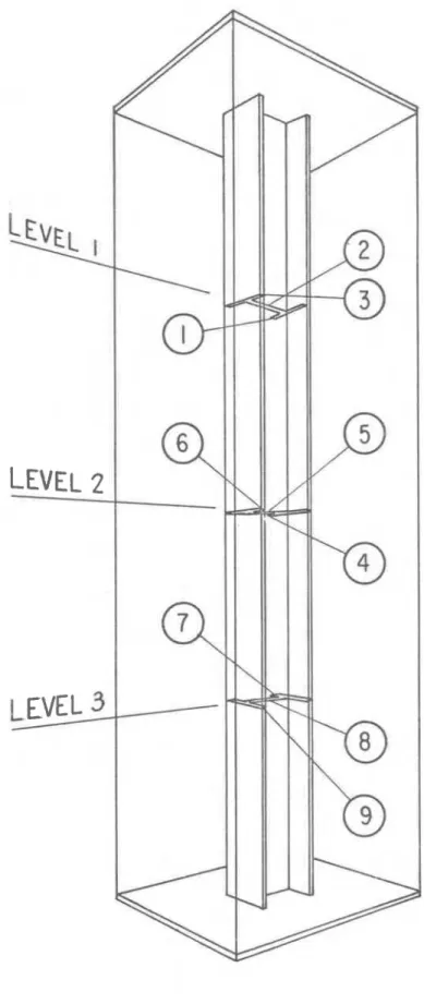
The f i r e endurance t e s t s w e r e c a r r i e d out e s s e n t i a l l y in a c c o r d - a n c e with CSA Standard B54.3- 1964 (8): A l t e r n a t e t e s t s of P r o t e c t i o n F o r S t e e l Columns. The t e s t deviated f r o m the s t a n d a r d in m e a s u r i n g the t e m p e r a t u r e on t h e column by using only 9 thermocouples a t 3 levels, a s shown i n F i g u r e 10. Two i n t e r m e d i a t e l e v e l s w e r e omitted b e c a u s e t h e r e was no r e a s o n t o expect f a i l u r e a t t h e s e c r o s s - s e c t i o n s . The c h r o m e l - a l u m e l thermocouples w e r e peened into the s t e e l section, and r e a d i n g s w e r e r e c o r d e d on a multi-point r e c o r d e r e a c h minute during the t e s t .
The f u r n a c e t e m p e r a t u r e was m e a s u r e d by nine thermocouples i n s t a l l e d in a m e t a l f r a m e c o n s t r u c t e d f r o m 13
/
16-in. 0 . D. Inconeltubes having 0. 035-in. wall thickness. The location of the f u r n a c e t h e r m o - couples is shown in F i g u r e 11. The hot junction of the thermocouples was
12 in. away f r o m the s u r f a c e of the specimen. Both the individual t e m - p e r a t u r e s a t nine points of the f u r n a c e and the a v e r a g e of the nine t h e r m o - couples w e r e r e c o r d e d . The f u e l input to the f u r n a c e was controlled to m a k e the a v e r a g e t e m p e r a t u r e follow a s c l o s e l y a s p o s s i b l e the p r e s c r i b e d t e m p e r a t u r e v e r s u s t i m e curve. The elevation of the b u r n e r s in the DBR floor f u r n a c e i s approximately a t level 3 on the column. In p a s t
t e s t s at this laboratory, failure has often occurred
at
t h i s level, due t oslightly higher furnace ternperatur es. H o w e v e r , this was not the c a s e in either
of t h e s e t e s t s , for reasons which will become apparent in subsequent
sections.
Figure 12 shows column No. 2 installed in the furnace immediately before t h e f i r e test.
OBSERVATIONS
DURING FIRE
TESTS Test. No. 1uring the f i r s t ten minutes the furnace was dark, making obser
-
vations difficult. However, flaming was seen at the joints of the sheet m e t a l a t 3 minutes, and the flaming continued until about 30 rninut es. By this t i m e the furnace t e m p e r a t u r e was sufficiently high t o permit good observations, and it was noticed that the s t e e l cover was warping somewhat and appeared t o be oxidizing on the surface. The warping, never too severe, continued progressively until about 2 hours. At 2 hours thesheet steel cover buckled outward slightly below the c e n t r e of the column
t h u s exposing the r o c k w o o l insulation near the top directly to the f i r e . At 2 hours and 8 minutes the s t e e l had slid well down the column (about 18 in. ) and the rock wool insulation had a l s o moved, s o that about
6
in. of the s t e e l section at the top was exposed t o t h e f i r e . By 2 hours and15 minutes 18 in. of the column w e r e b a r e , and the sheet s t e e l had warped and collapsed t o about 3 ft f r o m the top of the specimen. Only rock wool showed above the steel; not the gypsum wallboard.
The f i r e t e s t was terminated a t 2 hours and 20 minutes. Figure 1 3 shows the condition of the column s t i l l in the furnace after the f i r e t e s t . Figure 1 4 was taken after the column had been removed from the furnace and the sheet s t e e l and gypsum wallboard had been discarded.
T e s t No. 2
Nothing visibly significant happened throughout the t e s t . At 50 minutes the s t e e l was still in good condition, although slightly bulged in certain a r e a s . No vertical movement of the protection was observed throughout the t e s t .
The f i r e t e s t was terminated at 58 minutes. Figure 1 5 shows the condition of the specimen in the furnace after the t e s t , and Figure
16
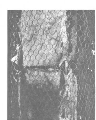
is a picture of the column outside the furnace with the insulation removed. The closeup in Figure 1 7 shows the condition of the rockwool insulation at the joint. This occurred at the mid height (level 2 ) of the column.
RESULTS
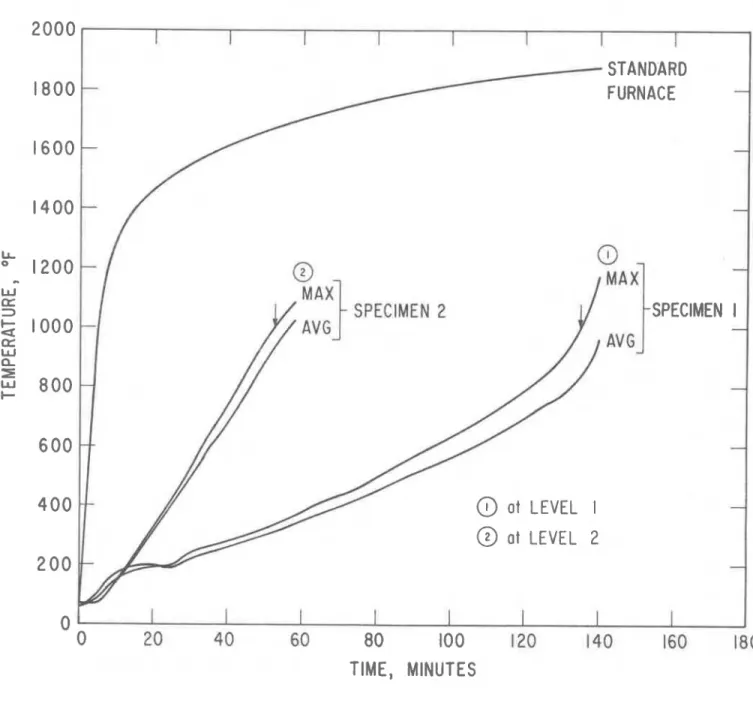
The average furnace t e m p e r a t u r e during the f i r e t e s t s was always within the allowable limits. Figure 18 is a plot showing the t e m p e r a t u r e r i s e of the columns.
Specimen No. 1 failed at level 1 at 135 minutes.
Specimen No. 2 exceeded the 1000" F allowable average t e m p e r a t u r e at level 2 (centre) a t 5 2 minutes.
Accordingly the specimens would receive f i r e endurance classifications of 2-hr and 3/4-hr respectively.
COMMENTS
These t e s t s both had interesting failures. The sliding down of insulation on specimen No. 1 caused the failure to occur at level 1, because only the rock wool remained a s insulation a t that height. It i s also possible, that because about 18 inches of the s t e e l column was exposed directly t o the f i r e , vertical heat conduction along t h e s t e e l section made a contribution t o the higher t e m p e r a t u r e s at level 1. At the t i m e of failure (135 min) the average t e m p e r a t u r e at level 1 was 110" F higher than the next highest average t e m p e r a t u r e at level 2.
Specimen No. 2 failed at level 2, which i s where the joint in t h e r o c k wool insulation o c c u r r e d ( F i g u r e 17). This r e s u l t emphasizes t h e importance of placing thermocouples at such locations. At the t i m e nf failure ( 5 2 rnin) the average t e m p e r a t u r e at level 2 was 95 to 100'
higher than levels I and 3, which w e r e at approximately the s a m e average temperature.
The sheet m e t a l was chosen, in addition t o i t s f i r e resisting abilities, for i t s attractiveness and durability as a column cover. Its p r i m a r y function, however, is t o act a s a radiation shield, and in the c a s e of s p e c h e n No. 1, t o hold t h e deteriorating wallboard insulation in place. That i t performed the latter function for a long t i m e was shown c l e a r l y by the way the s t e e l cover suddenly collapsed due to buildup of the disintegrated wallboard near the bottom. If thicker s t e e l had been used, the collapse would have occurred at a l a t e r time. (Measurements on the s t e e l a f t e r the t e s t showed that it had oxidized to an average
N e v e r t h e l e s s , i t was shown that inexpensive insulating m a t e r i a l s , protected by a c o v e r of a s h e e t s t e e l m e m b r a n e , c a n provide f i r e protection to s t e e l column s e c t i o n s f o r up t o 2 h o u r s .
P A R T Ilk CONCLUSIONS
1. The s h e e t s t e e l m e m b r a n e c a s e , i n conjunction with inexpensive insulating m a t e r i a l s was shown to provide:
( a ) f i r e endurance classification of l $ - h r f o r a s t e e l b e a m
( b ) f i r e endurance classification of 3 1 4 to 2 - h r f o r s t e e l columns
2 . Thin s h e e t steel, when applied a s a p r o t e c t i v e m e m b r a n e ,
r e m a i n s in p l a c e f o r p e r i o d s of o v e r 2 hours.
3 . Sheet s t e e l is effective a s a m e m b r a n e protection when applied o v e r insulation on v e r t i c a l l y and horizontally placed m e m b e r s o r construction components.
ACKNOWLEDGEMENT
The author wishes to thank M r . E. P o r t e o u s and M r . J. Berndt, who c a r r i e d out the f i r e t e s t s .
REFERENCES
1. Stanzak, W. W. F i r e t e s t on a s t e e l wide-flange b e a m p r o t e c t e d with a one-inch gypsum-sanded p l a s t e r suspended ceiling m e m - brane. National R e s e a r c h Council of Canada, Division of Build- ing R e s e a r c h . F i r e Study No. 19, Ottawa, Aug. 1967.
(NRC 9764).
2. Stanzak, W. W. F i r e t e s t s on s t e e l wide-flange column
s e c t i o n s protected with gypsum- sanded p l a s t e r . National R e s e a r c h Council of Canada, Division of Building R e s e a r c h . F i r e Study No. 20, Ottawa, Jan. 1968. (NRC 9768).
3 . Blanchard, J. A. C. and
T.
Z. Harmathy. S m a l l - s c a l e f i r e t e s tf a c i l i t i e s of the National R e s e a r c h Council of Canada, Division of Building R e s e a r c h . F i r e Study No. 14, Ottawa, Nov. 1964. (NRC 8207).
4. F i r e t e s t s of building construction and m a t e r i a l s , ASTM Designation E l 19-61. A m e r i c a n Society f o r Testing and M a t e r i a l s
.
Philadelphia, P a .5. Robertson, A. F. and J. V. Ryan. P r o p o s e d c r i t e r i a f o r defining load f a i l u r e of b e a m s , f l o o r s and roof construction during f i r e t e s t . J o u r n a l of R e s e a r c h . National B u r e a u of Standards, 63C, Washington, 1959, p. 121
-
124.6. Stanzak, W. W. F i r e t e s t s on wide-flange s t e e l b e a m s p r o t e c t e d with gypsum- sanded p l a s t e r . National R e s e a r c h
Council of Canada, Division of Building R e s e a r c h . F i r e Study No. 16, Ottawa, M a r c h 1967. (NRC 9474).
7. M i n e r a l wool t h e r m a l building insulation. CSA Standard A 101
-
1968. Canadian S t a n d a r d s Association, Ottawa, Ont.8. Methods of f i r e t e s t s of walls, partitions, f l o o r s , roofs,
ceilings, columns, b e a m s and g i r d e r s . CSA Standard B54.3
-
19 64. Canadian S t a n d a r d s Association, Ottawa, Ont.FIGURE I
CONSTRUCTION DETAILS OF SPECIMEN USED IN BEAM TEST
B R . 4010-/Figure 2. Exposed
surface before fire test.
Figure 3. Unexposed
surface before fire test.
F I G U R E 4 T H E R M O C O U P L E L O C A T I O N S
1500
Sheet Steel Membrane, Test 1
Beam o f C S A 640. 12 Steel ( A v g : 7, 8, 11, 12, 16 LL 1000 0 W w =2 C a D Z W n I 500 I 0 30 60 9 0 120 TI ME, MINUTES
FIGURE 5 BEAM TEMPERATURES
I
I
I
I
A d d 0. 75 i n . f o r S t a t i c D e f l e c t i o n
--
- -6;
i c r i t )
=0 . 4 8 i n . ~ m i n
-
-
-
. ' O -1
II
1
0
10
20
3 0
40
50
6 0
7 0
80
90
100
110
T I M E , M I N U T E S
F I G U R E 6
D E F L E C T I O N A N D R A T E O F D E F L E C T I O N
BR 4010- 4FIGURE
7
CONSTRUCTION DETAILS OF SPECIMENS USED IN COLUMN TESTS
Figure
8.
Columns under= I construction.
Figure
9.
Column No. 2 completed.DISTANCE FROM THE
BOTTOM PLATE
LEVEL
3, 2 FT
1'14
IN.
LEVEL 2 , 4 FT
1114
IN.
LEVEL
I
,
6 FT
1114
IN.
FIGURE
10
LOCATION
OF
THERMOCOUPLES
EAST
-
THERMOCOUPLE JUNCTION
FIGURE
II
F U R N A C E T H E R M O C O U P L E LOCATIONS
B R 4026 - 2Figure 14.
Column No.
1 partly dismantled after fire test.Figure 15. Column
No.
2 after Ifire test.
Figure
16.
Column No. 2 with steel cover removed after f i r e test.Figure 17. Column No. 2: insulation joint after test.