HAL Id: hal-01323670
https://hal.archives-ouvertes.fr/hal-01323670
Submitted on 30 May 2016HAL is a multi-disciplinary open access archive for the deposit and dissemination of sci-entific research documents, whether they are pub-lished or not. The documents may come from teaching and research institutions in France or abroad, or from public or private research centers.
L’archive ouverte pluridisciplinaire HAL, est destinée au dépôt et à la diffusion de documents scientifiques de niveau recherche, publiés ou non, émanant des établissements d’enseignement et de recherche français ou étrangers, des laboratoires publics ou privés.
Capillary infiltration of hexadecane in packed SiC
powder and in SiC/SiC preforms: Pore description and
calculation of molten Si infiltration
A Marchais, Jérôme Roger, Y Le Petitcorps
To cite this version:
A Marchais, Jérôme Roger, Y Le Petitcorps. Capillary infiltration of hexadecane in packed SiC powder and in SiC/SiC preforms: Pore description and calculation of molten Si infiltration. Ceramics International, Elsevier, 2016, �10.1016/j.ceramint.2016.01.203�. �hal-01323670�
1
Capillary infiltration of hexadecane in packed SiC powder and in SiC/SiC preforms: Pore description and calculation of molten Si infiltration
A. Marchais a, J. Roger a,*, Y. Le Petitcorps a
a
Université de Bordeaux, CNRS, Laboratoire des Composites ThermoStructuraux, UMR 5801, 33600 Pessac, France
* Corresponding author: e-mail: roger@lcts.u-bordeaux.fr, phone number: +33 5 56 84 47
36, fax number: +33 5 56 84 12 25
Abstract
A SiC/SiC-Si composite can be synthesized by molten silicon infiltration in a SiC preform impregnated with a slurry of SiC powder. The kinetics of molten silicon infiltration in such a porous material are unknown, and the experimental measurement is complex. The calculation of the rise kinetics for a liquid in a porous material is possible by applying the Washburn modified equation with an accurate description of the pores. The monitoring of the mass and front height variations during hexadecane infiltration in a submicronic SiC packed powder and in a preform filled with a SiC powder was used to characterize the porosity. In the case of a fibrous preform, the residual porosity is composed of inter-grain pores and cracks formed during the drying of the slurry. The results of this study suggest that the liquid progresses first in the inter-grain porosity of the powder. The rise kinetics of molten silicon into a preform were then evaluated by calculation based on the pore description obtained from hexadecane capillary infiltration experiments.
2
1. Introduction
SiC isimportant in a broad range of technological applications because of its wide band gap, good oxidation resistance, high thermal conductivity, low density, high stiffness and adequate toughness. SiC is a promising material for ceramic-matrix composites for the hot parts of the structures in engines [1,2]. The synthesis of SiC materials can be achieved by a reaction between silicon and carbon [3-6]. One way to synthesize dense SiC/SiC composites is liquid-silicon-infiltration (LSI), inducing a reaction between carbon powder as a filler and molten silicon [7]. The interaction between liquid silicon and carbon is complex and not fully understood. The reaction between pure silicon or alloyed silicon and carbon is sudden, strongly exothermic and generally incomplete, with remaining pores, carbon and/or free silicon [8-11]. The examination and the modelling of the reactive silicon infiltration in preforms filled with carbon is complex, and only a few studies have covered this topic [12-15]. One way to produce a dense composite material based on SiC is to reduce the porosity using the non-reactive infiltration of molten silicon in a SiC preform impregnated with SiC powder. The obtained SiC/SiC-Si composite has a temperature of use limited to the melting point of silicon (1414°C). Despite this limitation, this type of material is interesting for relatively low temperature uses. To optimize the non-reactive LSI process, it is important to know the infiltration dynamics of molten silicon in porous preforms to limit the degradation of the preform by dissolution-reprecipitation [16]. However, the in-situ measurement of the melt rise in the preform is difficult because of the elevated temperature, which must be higher than the melting point of silicon, i.e., 1414°C. Alternatively, the silicon infiltration kinetics can be deduced from capillary infiltration models based on the pore size. The most commonly applied experimental approach is to measure the infiltration height of wetting liquids with time [14,17-20]. This approach was used by S. Kumar et al. for the capillary infiltration of silicon in 3D-stitched C-C preforms [21,22]. However, the Si-C reaction has some effects via the temperature increase and the
3
porosity size decrease induced by the reaction. In the present paper, a non-reactive method is examined to elaborate SiC/SiC-Si composites. Prior to the silicon infiltration modelling, the pore sizes of the SiC powder compacts and of the fibrous SiC preforms after SiC powder impregnation are established by mercury porosimetry and the capillary infiltration of hexadecane at ambient temperature. Then, a mathematical model for the solvent infiltration can be established. On the basis of these results, an evaluation of silicon infiltration kinetics in SiC preforms is proposed.
2. Experimental
2.1 Starting materials
SiC powder was supplied by Marion Technologies Co. (France). The particles size distribution of this powder is characterized by a narrow distribution and a mean diameter d50 of 700 nm. The fibrous preforms are 3D interlock preforms with
Hi-Nicalon S fibres from Nippon Carbon Co. (Japan). A pyrocarbon interphase was deposited on the fibres by chemical vapour infiltration. Then, a thick protective coating of β-SiC was also deposited by chemical vapour infiltration from methyl-trichlorosilane. The characteristics of the SiC powder and of the SiC preforms cannot be detailed because of industrial interests. Laboratory grade hexadecane provided by Sigma Aldrich Co. (USA) was used for the capillary infiltration experiments. The SiC powder compacts and the preforms impregnated with SiC powder were made by slurry cast process, which is represented schematically in Figure 1. First, a slurry of the SiC powder is obtained by mixing the SiC powder with a solvent (water) and a dispersant. The preparation of the SiC slurry cannot be detailed because of industrial protection. The preform impregnation and the stacking of the SiC grains is promoted by applying a gaseous pressure gradient P1-P2 between the top and the bottom of the containment,
4
range between the normal pressure and four times the normal pressure. The possible values of P2 are the normal pressure and vacuum.
2.2 Characterization of the materials
The porosity ε of the samples was calculated by applying the formula ε = 1-da/dv with
the apparent density da obtained from water porosimetry (method based on buoyant
forces) and the true density dv measured from helium pycnometry (AccuPyc 1340
Micrometrics) for a sample volume of 0.4 cm3. Pore-size distributions were also
characterized by mercury intrusion porosimetry (Micrometrics Autopore IV) for a sample volume of 0.6 cm3. To identify the effect of the difference of pressure (P1 and
P2) applied during the slurry cast process, five combinations of conditions were tested in
the absence of a preform. The corresponding conditions and the obtained samples, called A, B, C, D and E, are listed in Table 1. The corresponding porosities were determined for the 5 samples and are given in Table 1. The porosity values ε of the powder compacts are similar, between 50.1 and 53.2 %. The appearance of the compacted powder obtained for sample D (P1 = 4 bar, P2 = Patmospheric) is presented in
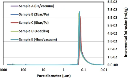
Figure 2. The micrographic observations were perfromed with a FEI Quanta 400 FEG scanning electron microscope operated at 5 kV. The volumes of mercury intruded in the powder compacts as a function of the applied pressure are reported in Figure 3. These results are consistent with small pore diameters ranging from 0.30 µm to 0.02 µm with a median pore size diameter close to 0.18 µm. The analyses indicate that the pressure gradient has a very small effect on the grain stacking. The starting preform was also impregnated with SiC powder by a slurry cast process to reduce the porosity. The chosen conditions of impregnation were P1 = 4 bar and P2 = Patmospheric. The mean mass
of SiC powder inserted in the preform is approcimately 210 mg for 1 g of preform. Three preforms, named samples F, G and H, prepared with these conditions were examined. The residual porosities ε measured for the three preforms before and after
5
slurry cast are given in Table 2. The mean residual porosity after slurry cast is approximately 25.5%. The volumes of mercury intruded in the preforms after infiltration of SiC powder are reported in Figure 4. The residual intratow porosity is negligible. The inter-grain porosities in the preform are similar to those measured on the powder compacts. A new type of porosity is identified near 10 µm, corresponding to cracks in the matrix. These porosities are generated duringthe drying of the infiltrated powder because of the presence of fibres, which limits the volume shrinkage. This effect is observable in Figure 5, corresponding to a preform impregnated with SiC powder.
2.3 Capillary infiltration of solvent
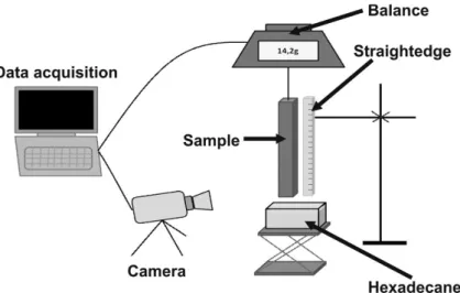
The capillary infiltration experiments were perfromed at 25°C on self-made equipment. Figure 6 represents the experimental setup for the column of the wetting experiments. The samples, packed SiC powder or SiC-powder-impregnated preform, with sizes close to 100x10x3 mm3 were hanged along their largest dimension to a modified analytical
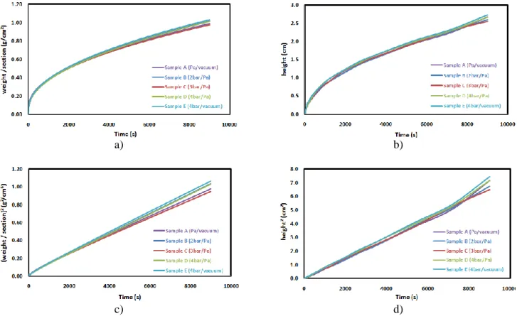
balance, which was connected to a computer. A beaker containing the solvent (hexadecane) was raised through an automatic lifter controlled by a step motor system. The surface location of the liquid was measured using a camera connected to a computer for visualization and to record the images. The mass and wetting height variations were recorded up to 9000 seconds. The liquid height reached approximately one third of the total height of the samples. Losses due to solvent evaporation were measured and estimated to be less than 1% of the imbibed solvent mass and were hence considered negligible. Table 3 lists the properties of the hexadecane solvent. The time dependence of hexadecane infiltration in the SiC powder compacts and in preforms impregnated with the SiC powder was recorded by monitoring the normalized weight gains and the solvent front heights in the samples. The corresponding curves are plotted
6
in Figures 7-a,b) 8-a,b). Initially, hexadecane rises quickly in the blocks by capillary action with a regular front. For longer durations, the infiltration rate is reduced. For short durations, the squared front height rises linearly with time [17,20,24]. A similar relation can be applied for the mass of hexadecane in the blocks because the height and the mass variations are correlated. The curves of the squared infiltration front heights and the squared normalized mass gains are plotted for all samples against time (Figures 7-c,d) 8-c,d)). In all cases, the squared infiltration front heights and squared mass gains curves vary linearly with the duration. The curves of the five SiC powder compacts (samples A, B, C, D, and E) are similar, confirming the limited effect of the slurry casting conditions (Fig. 7). The curves obtained with the SiC-impregnated preforms (samples F, G, and H) are slightly different (Fig. 8). In particular, the curves of the sample H are lower than the two other preforms, which can be explained by the larger residual porosity.
2.4 Analysis of the capillary infiltration of the solvent
The capillary infiltration data can be analysed by two approaches, corresponding to the Darcy law and the Washburn equation [15,20,24,25]. In the present case, the data were analysed using the Washburn equation (Equation 1) relative to the porosity radius:
r dt dh r h gh r dt dh h r dt d 2 2 2 . 8 cos 2 Equation 1
where t is the time, r is the radius of the medium pore, h is the infiltration height, ρ is the density, σ is the surface tension, and θ is the contact angle, which is assumed to be 0 due to the very low surface tension of hexadecane and η the dynamic viscosity. This equation can be simplified in the case of small radii capillaries with creeping flow.
Then,
dt dh h dt
d . is close to 0. Equation 1 can be modified as follows [21]:
gh r dt dh r h 2 cos 8 2 Equation 2
7
For short durations,
dt dh r h gh 8 2.
, then the equation can be written as:
t r h 2 cos 2 Equation 3 or: d t h eff 4 cos 2 Equation 4
where deff is the effective diameter of the porosity equal to 2r. From the linear fit of the
curves h2 = f(t), it is possible to determine the effective diameter deff of the porosity. The
mass increase during the infiltration of the liquid can also be used to calculate the value of the effective diameter deff by modifying Equation 4:
d S t m eff 2 2 2 2 4 cos Equation 5
where m is the infiltrated mass of the liquid, ρ is the density of the liquid, ε is the initial porosity of the sample, and S is the infiltration section of the sample. The effective diameter can be determined from the linear regression of the plots corresponding to the
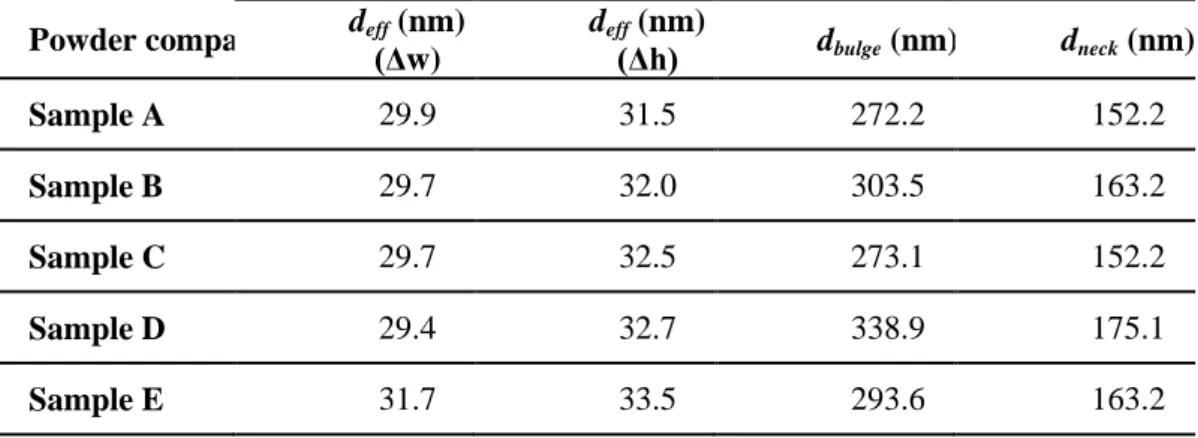
m2 = f(t) curves (Fig. 7-c) and Fig. 8-c)) and h2 = f(t) curves (Fig. 7-d) and Fig. 8-d)). These values were determined for all samples, and the values of the effective diameters are reported in Table 4. The deff values of the packed powder samples calculated from
the infiltration weight gain are between 29.4 and 31.7 nm. The values from the infiltration height are between 31.5 and 33.5 nm. Despite the slightly greater values from the front height measurements, these values are similar, which indicates a direct correlation between the mass and the front height increase during the infiltration of the solvent in packed powder. In other words, the porosities below the infiltration front are fully filled, which confirms the accuracy of these analysis methods for a powder medium. The deff values of the impregnated preforms are very different depending on
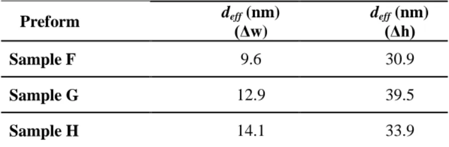
the analysis method. The values from the weight increase are always lower than the ones determined from the front height rise, with values between 9.6 and 14.1 nm and between 30.9 and 33.9 nm, respectively. These gaps are induced by the fibres of the
8
preform and by the drying cracks, which reveals the inexistence of a direct correlation between the mass and the front height variations during the infiltration. In others words, the porosities of the preform below the liquid infiltration front are not fully infiltrated by the liquid. The facts that the deff values from the infiltration front height increase for
the packed powder and the impregnated preforms are similar indicate that the infiltration of the solvent in the preforms occurs first in the blocks of powder. The explanation of this behaviour is the stronger wettability of the powder. A more detailed description of the porosity shape can be calculated for the packed powder. For a capillary tube, the effective diameter corresponds to the real diameter. However, for a porous medium, the effective diameter is the size of an equivalent capillary having the same behaviour. Some attempts have been made to theoretically model the effect of multiple radii and interconnections on capillarity flow. Dullien et al. [19,26] suggested the following equation:
1 3 2 . . 3 1 n k n j j k k n k k eff d d d d d Equation 6
where n is the number of different capillary sizes present in the unit cell of the equivalent porous medium and dk and dj are the corresponding diameters. For a packed
powder, a two-sizes model is considered as sufficient to describe the porosity with accuracy [27]. The equation for a two-size capillary model is:
1 3 lg lg 3 lg 2 lg . . 1 . 1 3 1 d d d d d d d d d neck e bu e bu e bu neck neck e bu neck eff Equation 7where dneck is the pore neck diameter and dbulge is the pore bulge diameter. A schematic
representation of this model is given in Figure 9. The effective diameter deff is obtained
from solvent impregnation experiments, and the neck diameter dneck is determined from
the mercury intrusion measurements. The neck diameter is the smallest pore diameter obtained for half of the mercury saturation [26]. The dneck values for all of the samples
9
values by applying Equation 7. The calculated dbulge values are also reported in Table 4.
The dbulge and dneck values of the packed powder are small, between 272.2 and 338.9 nm
for dbulge and between 152.2 and 175.1 nm for dneck. The smallness of the packed powder
porosities is favourable to their rapid impregnation by the solvent, which justifies the differences between the deff values from the packed powder samples and from the
impregnated preforms. The calculation of the dbulge and dneck values for the impregnated
preforms was not performed because of a lack of significance. An infiltration mechanism into powder-impregnated preforms can be proposed in two stages: during the first stage, the liquid rises preferentially in the blocks of the packed powder corresponding to the visible front with a partial filling of the porosities. During the second stage, the liquid fills the largest volumes of the preform, i.e., the drying cracks. From this work, it is possible to obtain an estimation of the infiltration kinetics of liquid silicon in a given preform on the basis of the data extracted from hexadecane infiltration experiments. The deff used for the calculation is 35 nm, which is the mean of the deff
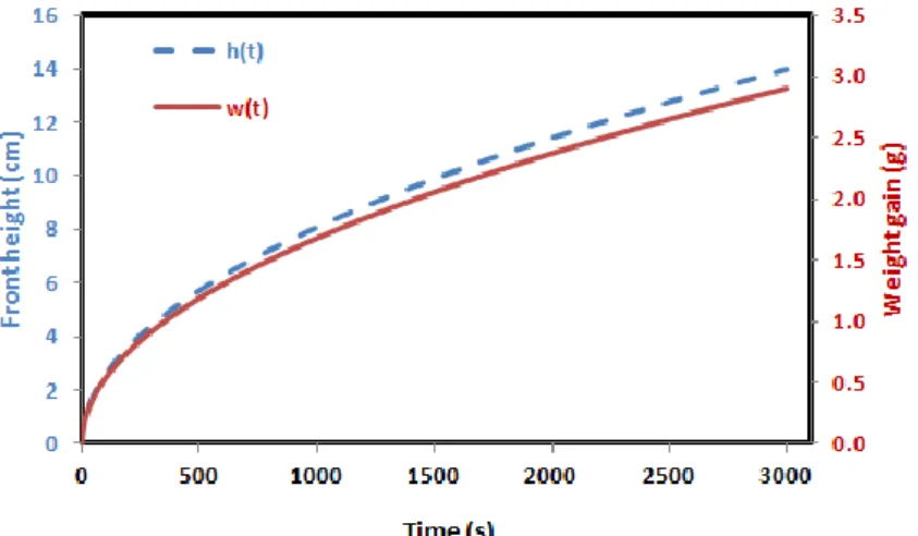
values obtained from the measurements on the three SiC preforms based on the front height increase (Table 5). The calculated curves of the liquid front height and of the weight increase during the rise of liquid silicon in a SiC-impregnated preform at 1420°C are given in Figure 10. The physical properties of molten silicon at 1420°C used for the calculations are given in Table 3. From these data, one can calculate the time for a complete silicon infiltration of the porosities for a given preform. The relevant data are the weight gains. The expected weight gain for obtaining a dense material can be determined beforehand on the basis of the overall porosity volume filled by the liquid.
3. Conclusion
To calculate the silicon rise kinetics in a given SiC preform impregnated with SiC powder, the residual porosity of the preform was examined by mercury intrusion and by monitoring the infiltration of hexadecane. The mercury intrusion experiments show that
10
the residual porosity in the preform corresponds to the inter-grain porosities and to the drying cracks of the powder. The monitoring of the mass and front height increases during hexadecane infiltration in packed-SiC powder is a method of characterizing the porosity by applying the Washburn modified equation. In this way, the effective diameter of the porosity in SiC compacts or in a SiC preform containing SiC powder can be obtained. The Dullien model was convenient for a more detailed description of the pores but only for a packed powder. This model was applied with two characteristic diameters, defined as the bulge and neck diameters of the porosity. For a preform impregnated with SiC powder, the effective diameters from the mass and liquid front height variations during solvent infiltration did not agree. The values from the liquid front height progression in a preform are similar to the values of the packed powder, suggesting that the liquid progresses preferentially in the inter-grain porosity of the preform. The smallness of the bulge and neck diameters describing the porosity of the packed powder indicates the preferential progression of the solvent in the inter-grains porosity of the powder. Therefore, the approach used in this work provides a description of the porosity in a packed-powder material. It is then possible to estimate the kinetics of silicon infiltration in a preform or in a powder compact at any temperature. In the case of powder compacts, the duration for a full densification can be calculated from the front height rise or from the weight gain. For a preform, only the weight gain model can be used to determine the duration for a full densification.
11
References
[1] K.K. Chawla, Ceramic Matrix Composites, second ed., Kluwer Academic Publishers, Boston, 2003, pp. 417-419.
[2] N.P. Bansal, Hand Book of Ceramic Composites, Kluwer Academic Publishers, Boston, 2005, pp. 117-147.
[3] P. Sangsuwan, S.N. Tewari, J.E. Gatica, M. Singh, R. Dickerson, Reactive infiltration of silicon melt through microporous amorphous carbon preforms, Metall. Mater. Trans. B, 30 (1999) 933-944.
[4] Y. Pan, J.L. Baptista, Spontaneous infiltration of iron silicides into silicon carbide powder preforms, J. Am. Ceram. Soc., 83 (2000) 2919-2924.
[5] Y. Wang, S. Tan, D. Jiang, The effect of porous carbon preform and the infiltration process on the properties of reaction-formed SiC, Carbon, 42 (2004) 1833-1839. [6] W.B. Tian, H. Kita, H. Hyuga, N. Kondo, Synthesis, microstructure and mechanical
properties of reaction-infiltrated TiB2–SiC–Si composites, J. Alloys. Compd., 509
(2011) 1819-1823.
[7] W. Krenkel, Carbon-fiber reinforced CMC for high perfromance structures, Int. J. Appl. Ceram. Tech., 1 (2004) 188-200.
[8] R. Pampuch, E.Walasek, J. Bialoskbrski, Reaction mechanism in carbon-liquid silicon systems at elevated temperatures, Ceram. Inter., 12 (1986) 99-106.
[9] R. Pampuch, J. Bialoskbrski, E. Walasek, Mechanism of reactions in the Sil + Cf
system and the self-propagating high-temperature synthesis of silicon carbide, Ceram. Inter., 13 (1987) 63-68.
[10] J.C. Margiotta, D. Zhang, D.C. Nagle, C.E. Feeser, Formation of dense silicon carbide by liquid silicon infiltration of carbon with engineered structure, J. Mater. Res., 23 (2008) 1237-1248.
12
[11] R. Voytovych, R. Israel, N. Calderon, F. Hodaj, N. Eustatopoulos, Reactivity between liquid Si or Si alloys and graphite, J. Eur. Ceram. Soc., 32 (2012) 3825-3835.
[12] R.P. Messner, Y.M. Chiang, Liquid-phase reaction-bonding of silicon carbide using alloyed silicon-molybdenum melts, J. Am. Ceram. Soc., 73 (1990) 1193-1200.
[13] H.P.G. Darcy, Les fontaines publiques de la ville de Dijon, Exposition et application des principes à suivre et des formules à employer dans les questions de distribution d’eau, Victor Dalmont, Paris, 1856.
[14] E.O. Einset, Capillary infiltration rates into porous media with applications to silicomp processing, J. Am. Ceram. Soc., 79 (1996) 333-338.
[15] P. Sangsuwan, S.N. Tewari, J.E. Gatica, M. Singh, R. Dickerson, Reactive infiltration of silicon melt through microporous amorphous carbon preform, Metall. Mater. Trans. B, 30 (1999) 933-944.
[16] J. Roger, A. Marchais, Y. Le Petitcorps, Examination of the interaction between liquid silicon and bulk silicon carbide, J. Cryst. Growth, 426 (2015) 1-8.
[17] E.W. Washburn, The dynamics of capillary flow, Phys. Rev., 17 (1921) 273-283. [18] B.S.S. Daniel, D. Mazumdar, V.S.R. Murthy, Modeling of composite growth in the
directed aluminum melt nitridation process, Metall. Mater. Trans. A, 30 (1999) 2951-2958.
[19] F.A.L. Dullien, Porous Media: Fluid Transport and Pore Structure, Academic, New York, 1979.
[20] D.V. Trong, J. Hupka, Characterization of porous materials by capillary rise method, Physicochem. Probl. Min. Process., 39 (2005) 47-65.
[21] S. Kumar, A. Kumar, A. Shukla, A.K. Gupta, R. Devi, Capillary infiltration studies of liquids into 3D-stitched C–C preforms Part A: Internal pore characterization by
13
solvent infiltration, mercury porosimetry, and permeability studies, J. Eur. Ceram. Soc., 29 (2009) 2643-2650.
[22] S. Kumar, A. Kumar, R. Devi, A. Shukla, A.K. Gupta, Capillary infiltration studies of liquids into 3D-stitched C–C preforms Part B: Kinetics of silicon infiltration, J. Eur. Ceram. Soc., 29 (2009) 2651-2657.
[23] U. Onken, J. Rarey-Nies, J. Gmehling, The Dortmund Data Bank: A computerized system for retrieval, correlation, and prediction of thermodynamic properties of mixtures, Int. J. Thermophys., 10 (1989) 739-747.
[24] M. Abraham, D.C. Ruben, Characterization of porous media by the kinetics of liquid penetration: vertical capillaries model, J. Colloid Inter. Sci., 189 (1997) 299-304.
[25] S.G. Advani, E.M. Sozer, Process Modeling in composite Manufacturing, fifteen ed., Marcel Dekker, New York, 2003.
[26] F.A.L. Dullien, M.S. El-Sayed, V.K. Batra, Rate of capillary rise in porous media with nonuniform pore, J. Colloids Inter. Sci., 60 (1977) 497-506.
[27] P.C. Carman, Flow of gases through porous media, first ed., Butterworths Scientific Publications, London, 1956.
14
Figure 1: Outline of the slurry cast process
Figure 2: Backscattered electrons image of silicon carbide powder compact (Sample D)
15
Figure 4: Size-pore distribution of SiC preforms densified with SiC powder: samples F, G, and H
Figure 5: Backscattered electrons image of SiC fibrous preform densified by SiC powder (with P1/P2= 4bar/Patm) and after silicon
infiltration
16
a) b)
c) d)
Figure 7: Time dependence of hexadecane capillary infiltration into powder compacts with: a) weight gain, b) front height, c) squared weight gain, and d) squared front height
a) b)
c) d)
Figure 8: Time dependence of hexadecane capillary infiltration into SiC powder densified preforms with: a) weight gain, b) front height, c) weight gain squared, and d) front height squared
17
Figure 9: Schematic representation of a two-size capillary repeating unit with pore neck diameter dneck and pore bulge diameter dbulge used for packed
powder samples
Figure 10: Calculated curves of the front height and weight gain versus time during silicon rise at 1420°C in an impregnated SiC preform with the deff
18
Table 1: Conditions of the slurry cast process used for the silicon carbide powder compacts and the corresponding porosity
Powder
compact P1 P2 Porosity ε (%)
Sample A atmospheric primary vacuum 50.6
Sample B 2 bar atmospheric 53.2
Sample C 3 bar atmospheric 50.1
Sample D 4 bar atmospheric 52.3
Sample E 4 bar primary vacuum 51.8
Table 2: Porosity of the silicon carbide preforms before and after the slurry cast of the SiC powder
Preform Porosity ε
before the slurry cast (%)
Porosity ε after the slurry cast (%)
Sample F 35.2 26.2
Sample G 35.5 24.8
Sample H 34.5 25.5
Table 3: Physical properties of hexadecane at 25°C and silicon at 1420°C [23] Hexadecane Silicon
Wetting angle on SiC (°) 0 38
Density ρ (g.cm-3) 0.77 2.52
Dynamic viscosity η (mN.m-1) 0.030 0.008
Surface tension σ (g.s-2) 27.4 740
Table 4: Correlation between deff, dneck and dbulge for the SiC packed powder samples from the
variations of the weight (Δw) and the front height (Δh) during hexadecane infiltration Powder compact deff (nm) (Δw) deff (nm) (Δh) dbulge (nm) dneck (nm)
Sample A 29.9 31.5 272.2 152.2
Sample B 29.7 32.0 303.5 163.2
Sample C 29.7 32.5 273.1 152.2
Sample D 29.4 32.7 338.9 175.1
19
Table 5: Determination of the effective diameter deff, for the preform densified by the SiC
powder from the variations of the weight (Δw) and the front height (Δh) during hexadecane infiltration
Preform deff (nm) (Δw) deff (nm) (Δh)
Sample F 9.6 30.9
Sample G 12.9 39.5