HAL Id: in2p3-00192376
http://hal.in2p3.fr/in2p3-00192376
Submitted on 27 Nov 2007
HAL is a multi-disciplinary open access
archive for the deposit and dissemination of
sci-entific research documents, whether they are
pub-lished or not. The documents may come from
teaching and research institutions in France or
abroad, or from public or private research centers.
L’archive ouverte pluridisciplinaire HAL, est
destinée au dépôt et à la diffusion de documents
scientifiques de niveau recherche, publiés ou non,
émanant des établissements d’enseignement et de
recherche français ou étrangers, des laboratoires
publics ou privés.
The SISSI project : an intense secondary ion source
using superconducting solenoid lenses
A. Joubert, E. Baron, C. Grunberg, J.D. Larson, W. Mittig, F. Ripouteau
To cite this version:
A. Joubert, E. Baron, C. Grunberg, J.D. Larson, W. Mittig, et al.. The SISSI project : an intense
sec-ondary ion source using superconducting solenoid lenses. 1991 IEEE Particle Accelerator Conference,
May 1991, San Francisco, United States. pp.594-597, �10.1109/PAC.1991.164374�. �in2p3-00192376�
The SISSI Project :
An Intense Secondary Ion Source
Using Superconducting Solenoid Lenses
A. Joubert, E. Baron, C. Grunberg, J.D. Larson (*) , W. Mittig, F. Ripouteau GANIL - B.P. 5027 - F14021 Caen cedex
Abstract
Secondary beams are routinely produced at GANIL for experiments from a target placed in the high energy beam line of the accelerator. In order to make a better use of the higher beam intensities soon available at GANIL, a proposal called “SISSI” was presented in 1989. This project is now funded. It consists of a set of two superconducting solenoid lenses of very short focal length (.6m). The first solenoid is used to sharply focus the incoming beam on a fast moving target. The second increases the angular acceptance of the beam line downstream the target for charged reaction products. Calculations show that from a .4mm diameter beam spot on the target, an acceptance angle of up to 80 mrad will be reached without significant emittance growth due to aberration effects. Technical aspects of that project are then presented concerning both the solenoids and the cryogenic devices as well as the solid target.
I.
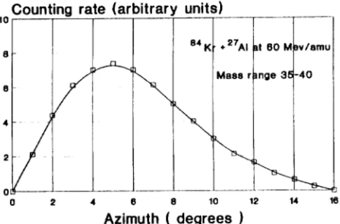
INTBODUCTI~NSince the very beginning of experiments at GANIL, secondary beams have played an important role. The dominant reaction mechanism at 50 - 100 Mev/nucleon is a fragmentation-like process which gives secondary products that are distributed in the forward direction (figure 1). This property together with a small energy spread provides the opportunity to transport and collect them efficiently. The extensive use of such beams with magnetic spectrometers LISE and SPEG (associated with a very long 116 m time of flight path) had allowed us to perform a rich variety of experiments.
The main limitation to the broad range of physics opened by secondary beams [ 1 ] is their rather poor intensity. One possible way to overcome this is to increase the primary beam intensity. With modifications of the injector system, already realized or to be done in the near future, intensities of 5.1013 and 2.1012 particles/s on target will be available for Ar and Kr, respectively. Another and complementary way of increasing the secondary beam intensity is to improve the transmission of the beam line. A device called SISSI (“Source d’Ions Secondaires a Supraconducteurs Intenses”) composed of two short-focal-length magnetic lenses is being constructed for this purpose.
II.
MAINSPRING OF OPERATIONA peak of secondary charged particles exists in the range 50-100 mrad (figure 1). Only a small fraction of the secondary particles can be transported due to the 5 mrad angular acceptance at the entrance of the GANIL beam line. By enlarging the angular acceptance up to 80 mrad or more, we expect to capture most of the secondary production. A large
----___-
(*) - Independent physicist, Independence, MO, U.S.A.
angle acceptance implies a short focal length lens like S2 (figure 2)
wh h
‘c collects and refocuses the secondary beam2ounting r6
_1..
3 (al itrary unii I
u
__.
.-
0 2 4 Azinhh (8degrLk9 1 12 14 16Figure 1 : Typical counting rate as a function of azimuth for secondary charged particles.
PRIMARY BEAM
Figure 2 : Principle of the use of a two lens device for increasing the angular acceptance of the beam line downstream the target.
according to the usual beam line matching conditions. Due to Liouville’s theorem, the primary beam spot size must decrease in inverse proportion to the angle increase. This is achevied by the first lens Sl which focuses the incoming beam to a small size spot (0.4 mm in diameter) on the target. Such an arrangement was envisioned by H. Wollnik in the seventies [2], but without
the
advances in superconducting technology during the recent years, a realization would not have been possible at GANIL energies.III. THE LENSES
Due both to the relatively high magnetic rigidity of the expected particles (2.9 Tm) and the short insertion length
594
© 1991 IEEE. Personal use of this material is permitted. However, permission to reprint/republish this material for advertising or promotional purposes or for creating new collective works for resale or redistribution to servers
available for SISSI (2.35 m), very short focal lengths are required [3]. The maximum available length for each lens is 800 mm. A brief study showed that quadrupoles would not be suitable elements. The field gradient is too high and the magnetic field configuration is not well defined because each magnet would have a large aperture compared with its short length. Therefore, we have chosen solenoids although their focusing power is lower than that of quadrupoles. The main advantages are :
- the design and realization are comparatively easy, - the beam remains axially symmetric,
- the magnetic volume is satifactorily filled with the beam.
Conversely, the focusing power being relatively weak, the field inside the solenoids must be 11 T at least.
IV. EXPECTED
OPTICAL PROPERTIES
The optical purpose of SISSI is to change the beam profile to adapt to the beam line acceptance. Defects and aberrations are not important as long as they do not change the beam transmission. The axial field distribution of the solenoids has no critical effect on the beam dimensions and is unimportant compared to focal aberrations [4].Radius(mm)
O,l
Phase spice area(A/ rr’km.mrad)
100
Figure 3 : Contribution of several types of distortion on the spot size at the target.
Scattering angle(mrad)
Figure 4 : Effect of spherical aberrations on the transmittable emittance.
Figure 3 emphasizes the effect of several types of distortions on the spot size at the target. With an incoming beam emittance of 5rrmmmrad, the outer radius, including geometrical and chromatic aberrations (for an energy spread of
10s3) and multiple scattering within standard 1 mm thick target, is very close to 0.2 mm. That is the desired goal and seems to be compatible with the SISSI design.
Similar properties were found for the secondary beam. Figure 4 illustrates the effect of spherical aberrations on transmittable secondary beam phase space. The beam line was designed to carry a beam with an upper emittance value of 20 rmmmrad. For a spot size of 0.4 mm in diameter, the effective angular limitation (70-80 mrad) is mainly due to spherical aberrations.
V. SISSI DESIGN
To get the required high magnetic field values we use superconducting solenoids.
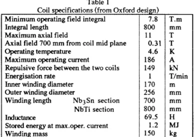
The coils consist of two identical solenoids Sl and S2, their parameters are listed in table 1. They will be designed and manufactured by Oxford Instruments 151.
Table 1 Coil specifications (from Oxford Minimum operating field integral
Integral length Maximum axial field
Axial field 700 mm from coil mid plane Operating temperature
Maximum operating current
Repulsive force between the two coils Energisation rate
Inner winding diameter Outer winding diameter
Winding length Nb3Sn section NbTi section Ind-
Stored energy at max.oper. current Winding mass de T
sign)
7.8 800 11 0.31 4.6 186 149 1 170 256 700 800 69.5 1.2 150 T.m mm T T K A kN T/min m mm mm mm H MJ kgThe configuration chosen for each solenoids is duplex co-axial coils. The inner section which experiences the highest fields is made of Nb3Sn round wire conductor of the tin core “Modified Jelly
Roll”
(MJR) type. For the outer section, NbTi conductors of radially graded sizes are used. Both Nb3Sn and NbTi sections will operate at 4.6 K in a common vessel.Strings of cold diodes with series resistors are mounted inside the cold box as quench protection circuit. Their number, as well as the corresponding coil sections, are designed so as to optimize both temperature and voltage rises during a quench.
All coils are impregnated with epoxy resin by standard techniques.
Bach solenoid is independently powered, current being adjustable.
Figure 5 presents a schematic drawing of the cryostat. Coils are located on both sides of a vertical tube into which the target is inserted. The inner pipe is a part of the beam line and operates at room temperature. A thermal shielding limits thermal exchanges between coils and warm parts of the cryostat (beam tube, target location and outer shell). The solenoids will
yENOiD St HELIUH VESS? ! SOLENOID 52 ~ CRYOSTdj ,VACUUM CRYOGENIC HljH QUALITY
VACUUI ;~Cl~TINO~ IINSULATED) j
2350
Figure 5 : Schematic drawing of the coils inside their cryostat.
be aligned within the cryostat and the cryostat then used to align the lenses to the beam axis.
SISSI wil operate inside the accelerator vault which is inaccessible most of the time. As a consequence a classical liquid helium supply system with container handling would introduce unacceptable constraints and higher operating cost.
The recent availability of a closed cycle refrigerator developed by CEA [6] solves this problem. The liquid helium cooling the solenoids is fully separated from the helium used in the closed cycle refrigerator. Helium evaporated from the helium vessel is reliquified by a refrigerated cold head. So, except for the cooldown period, the cryogenic system will require neither continuous tilling nor the need for helium recovery.
An improved version of existing closed cycle refrigerator will be specially designed by CEA with a cooling capacity of 2.2 W at 4.6 K. The estimated total thermal loss is around 1.3 W at 4.6 K.
The refrigerator will be installed together with the three current leads in a satellite box which is a part of the cryostat.
VI. THE TARGETENVIRONMENT
The IOO-to-500 mg/cm2 thick target, located at the image point of the first solenoid, has to be made of high melting point material (> 1000 “C), for example Be, C, Ti, Ni, Zr, MO or Ta, in order to stand the high beam power deposited in it (up to about 1 kW). To cool this target, it is planned to move it with respect to the beam so as to extend the radiation area and to get a better temperature distribution. We developed a computer program to solve the heat equation, taking into account both conduction and radiative cooling, and including a target motion. Checks of the results are being prepared by measurements of target temperature when bombarded by the present GANIL beam. Depending on the mechanical solution chosen for this motion, the target frame will be cooled either by circulation of a coolant or by addition of radiators. Provision must be made for a secondary target located downstream, to fully stop the primary beam and to slow down
the reaction products in order to adapt their magnetic rigidity to that of the existing beam line.
The mechanical design is just beginning. In addition to cooling, it has to take into account eddy currents generated by the high magnetic fields of the solenoids, thermal shielding of the cryogenic environment, radiation protection aspects associated with the target activation and, we must not forget, energy deposited by the neutrons and the gamma rays in the superconducting windings.
VII.
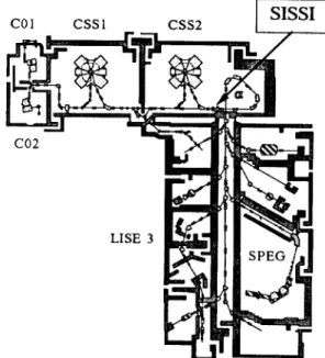
IMPLEMENTATIONSecondary beams must be delivered in any experimental room. SISSI will therefore be located above the switchyard and experimental areas (figure 6).GANIL has to work either with or without SISSI. It must be considered as one more lens system on the beam line, and not as a device designed to replace existing lenses. Any time SISSI does not work, the standard matching process will be used.
Figure 6 : General overview of GANIL showing the location of SISSI.
VIII.
CONCLUSIONIX.
REFERENCES Located at the exit of the second cyclotron (CSS2),SISSI will permit the use of the secondary beams by all the existing experimental instruments. It will increase the intensity of the transmitted secondary beam by a factor of fifty.
The chosen technical solutions appear realistic and should result in easy and rather low cost operation.
The two main parts (a pair of solenoids with their cold box, a cryostat with its cryogenic satellite) have been ordered. According to the schedule, SISSI should be installed on the GANIL in January 1993 and tested in operational conditions within the two following months.
[II
Radioactive Nuclear Beams, Int. Conf., Berkeley, Oct. 1989.121 H. Wollnik, N.I.M. 83 (1970), 229-231.
131 C. Grunberg, J.D. Larson, W. Mittig, F.Ripouteau, Internal report - GANIL R89-09.
[41 J.D. Larson, private communication, 1990- 199 1.
151
Oxford Instruments Ltd, Eynsham, Oxford OX8 ITL, England.[61 G. Claudet et al., CEA/DRFMCISBT, Cryogenics 1990, Vol 630,272-216.
597