Design and Analysis of Lunar Lander Control
System Architectures
by
Joseph M. Morrow
B.S. Aerospace Engineering North Carolina State University, 2010
ARCHIVES
AGUSETTS iNS TE
SCHNOLOGY
L
BA RIES
Submitted to the Department of Aeronautics and Astronautics in Partial Fulfillment of the Requirements for the Degree of
Master of Science in Aeronautics and Astronautics
at the
Massachusetts Institute of Technology June 2012
@ Joseph M. Morrow, 2012. All rights reserved.
The author hereby grants to MIT, Draper Laboratory, and NDSEG permission to reproduce and distribute publicly paper and electronic copies of this thesis in whole or in part.
Signature of Author:
vvv
Department of Aeronautics and AstronauticsMay 24, 2012
Certified by:
~KWJ
7>
Jeffrey A. Hoffman
Professor of the Practice of Aerospace Engineering Thesis Supervisor
Certified by:
Brett J. Streetman Senior Member of the Technical Staff, Draper Laboratory Thesis Supervisor
/t I a Accepted by:
/
Eytan H. Modianorofessor of Aeronautics and Astronautics Chair, Graduate Program Committee
Design and Analysis of Lunar Lander Control
System Architectures
by
Joseph M. Morrow
Submitted to the Department of Aeronautics and Astronautics on May 24, 2012, in Partial Fulfillment of the
Requirements for the Degree of Master of Science in Aeronautics and Astronautics
Abstract
Although a great deal of separate work exists on the development of spacecraft actuators and control algorithm design, less work exists which examines the connections between the selection of specific actuator types and placements, how this affects control algorithm design, and how these combined factors affect the overall vehicle performance of a lunar lander. This thesis attempts to address these issues by combining a functionality-oriented approach to actuator type/placement with a controls-oriented approach to algorithm design and performance analysis. Three example control system architectures are examined for a generic autonomous 350kg lunar lander during the terminal descent flight phase. Results indicate that stability and control can be achieved using a wide variety of actuator types/placements and algorithms given that a set of 'common sense' subsystem functionality and robustness metrics are met; however, algorithm development was often heavily influenced/restricted by actuator system capabilities. It is therefore recommended that future designers of lunar lander vehicles consider the impact of their control system architectures from both a functionality-oriented and a controls-oriented approach to gain a more complete understanding of the effects of their choices on overall performance.
Thesis Supervisor: Jeffrey A. Hoffman
Title: Professor of the Practice of Aerospace Engineering Thesis Supervisor: Brett J. Streetman
Acknowledgments
I would like to thank my advisors, Jeff and Brett, for their guidance over the past two years as well as my parents, my sister, and Jessica for their love and support. I would also like to thank the numerous MIT students and faculty, Draper employees, and friends that made my graduate experience worthwhile. "I was supported by the Department of Defense (DoD) through the National Defense Science &
Engineering Graduate (NDSEG) Fellowship Program."
Publication of this thesis does not constitute approval by Draper or the sponsoring agency of the findings or conclusions contained herein. It is published for the exchange and stimulation of ideas.
Table of Contents
List of Figures ... 11
List of Tables...16
Acronym s and Abbreviations...17
Variables and Constants...18
1 Introduction ... 19
1.1 Nom inal M ission Descent Trajectory ... 20
1.2 Defining the Problem ... 21
1.3 Defining the Approach... 24
1.4 Im portant Definitions...24
2 A Historical Perspective ... 27
2.1 Surveyor (US)... 27
2.2 Apollo (US)... 29
2.3 Luna (USSR) ... 32
2.4 Constellat ion (US) ... 33
2.5 European Lunar Lander (ESA) ... ... 35
2.6 Chinese Lunar Exploration Program (CNSA) ... 35
2.7 Chandrayaan-2 (ISRO/Roskosmos)... 35
2.8 Com m ercial Efforts ... 36
2.8.1 Northrop Grum man Lunar Lander Challenge (US) ... 36
3 Actuators and Actuator Architectures ... 39
3.1 Actuators...39
3.1.1 W ays of Providing Force and Torque ... 39
3.1.2 W ays of Changing Linear and Angular Im pulse... 41
3.1.3 'Gim baled vs. Fixed' and 'Throttleable vs. Pulsed' ... 42
3.1.4 Choosing Thrust Levels... 43
3.2 Actuator Architectures...44
3.2.1 High Linear Im pulse Actuation System ... 44
3.2.2 Low Angular Im pulse Actuation System ... 45
3.2.3 Designed Coupling between Actuation System s ... 48
3.3 Sum m ary ... 52
4 Control Algorithm s and Algorithm Architectures ... 53
4.1 Nom inal Plant M odel...54
4.1.1 Spacecraft ... 54
4.1.2 Actuators...55
4.2 Control Algorithm Architectures... 55
4.2.1 Feedback Structures... 56
4.2.2 Specific Algorithm s...57
4.2.3 Algorithm Verification... 60
4.2.4 Other Factors to Consider ... 62
5 Case Studies ... 69
5.1 Prelim inary Discussion ... 69
5.1.1 Term inal Descent Trajectory... 69
5.1.2 Actuator Architecture Requirements... 72
5.1.3 Control Algorithm Architecture Requirements... 73
5.1.4 Com m on Simulation Architecture ... 74
5.2 Case 1: Multiple Fixed Nonthrottleable Thrusters for Attitude Control; Single Fixed Throttleable Engine for Altitude Control ... 77
5.2.1 Designing the Actuator Architecture ... 78
5.2.2 Designing the Control Algorithm Architecture ... 80
5.2.3 Perform ance and Verification... 97
5.2.4 Case 1 Sum mary...103
5.3 Case 2: Single Gimbaled Throttleable Engine for Altitude and Roll/Pitch Control; Multiple Fixed Nonthrottleable Thrusters for Yaw Control...105
5.3.1 Designing the Actuator Architecture ... 106
5.3.2 Designing the Control Algorithm Architecture ... 107
5.3.3 Perform ance and Verification...119
5.3.4 Case 2 Sum mary...124
5.4 Case 3: Multiple Nonthrottleable Thrusters for Altitude and Attitude Control (Three Fixed, One G im b a le d )...1 2 6 5.4.1 Designing the Actuator Architecture ... 127
5.4.3 Performance and Verification ... 142
5.4.4 Case 3 Summary...147
5.5 General Case Studies Summary ... 149
6 Conclusion...151
List of Figures
Figure 1-1: Lunar lander guidance, navigation, and control (GNC) framework...20
Figure 1-2: Nom inal descent trajectory ... 21
Figure 1-3: Scenario of interest for this thesis - Terminal Descent... 22
Figure 1-4: Control system architecture breakdow n ... 25
Figure 2-1: Surveyor trajectory [4]... 27
Figu re 2-2 : Su rveyo r lander [1]...28
Figure 2-3: A pollo m ission profile [10]... 30
Figure 2-4: Apollo Lunar M odule (LM ) [11] ... 31
Figu re 2-5 : Lu na 16, 20 [23] ... 32
Figure 2-6: A ltair Lunar Lander [24]... 34
Figure 2-7: Lunar Lander Challenge winners; (a) Xoie [34], (b) Scorpius Super Mod [37]... 37
Figure 2-8: GLXP testbeds; (a) Next Giant Leap's TALARIS [45], (b) Moon Express's LTV [44]... 38
Figure 3-1: Thruster system mass vs. total impulse comparison [23] ... 41
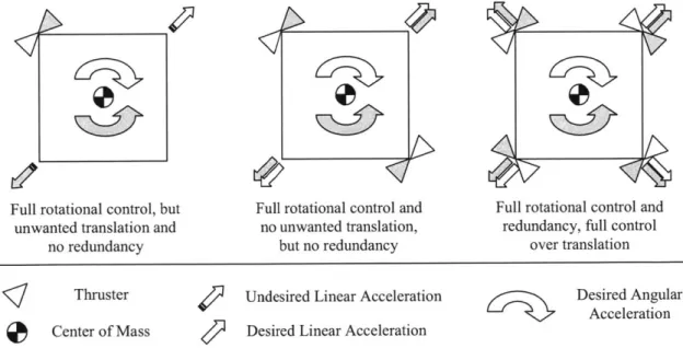
Figure 3-2: Thought process for choosing thruster number and position for a 2D rigid body...47
Figure 3-3: Example architecture 1 - single engine with thrust vectoring ... 50
Figure 3-4: Example architecture 2 -three engines with differential impulse ... 50
Figure 3-5: Example architecture 3 - four engines with differential impulse ... 51
Figure 4-1: Standard feedback structure with relevant block indicated ... 53
Figure 4-2: Example error feedback control architecture for double integrator system...56
Figure 4-4: Example state feedback control architecture... 57
Figure 4-5: Exam ple phase plane controller ... 60
Figure 4-6: Generic 'single slosh m ass' m odel... 65
Figure 5-1: Reference descent trajectory as a function of time; (a) altitude, (b) acceleration ... 70
Figure 5-2: Com m on sim ulation block diagram ... 74
Figure 5-3: Descent trajectory block diagram ... 75
Figure 5-4: Control algorithm s block diagram ... 75
Figure 5-5: Spacecraft dynam ics block diagram ... 76
Figure 5-6: Case 1 baseline actuator architecture ... 77
Figure 5-7: Pulsed actuator thrust profile... 81
Figure 5-8: (a) Time-fuel optimal controller, (b) Simplified controller with linear switch curves ... 84
Figure 5-9: Linear feedback architecture for simplified controller...84
Figure 5-10: Typical step command plots; (a) phase plane, (b) states, (c) inputs ... 85
Figure 5-11: Effect of modeling errors; (a) control power, (b) time delay ... 86
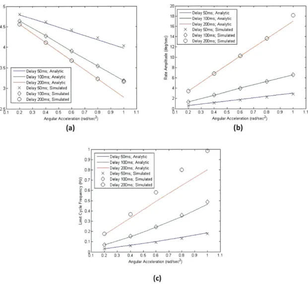
Figure 5-12: Limit cycle solutions; (a) angle amplitude, (b) rate amplitude, (c) frequency...88
Figure 5-13: Yaw step response; (a) phase plane, (b) states vs. time... 89
Figure 5-14: Roll and pitch step response; (a) phase plane, (b) states vs. time ... 90
Figure 5-15: Bias compensator signal prefilter; (a) Root Locus, (b) Bode ... 90
Figure 5-16: Roll and pitch response to 86.ON*m bias moment; (a) phase plane, (b) states vs. time...91
Figure 5-17: Altitude controller performance; (a) time domain tracking, (b) input sensitivity function ... 93
Figure 5-19: Lateral 1.0m step response; (a) position, (b) angles ... 96
Figure 5-20: Lateral 1.0m/sec impulse response; (a) position, (b) angles ... 96
Figure 5-21: Lateral response to 5.0cm CM offset in both axes at T/W= 1; (a) position, (b) angles ... 97
Figure 5-22: Nominal descent states; (a) altitude, (b) vertical velocity ... 98
Figure 5-23: Nominal descent states; (a) lateral positions, (b) angles... 98
Figure 5-24: Nominal descent control; (a) throttle, (b) desired moments ... 99
Figure 5-25: Nominal descent actual body frame control; (a) forces, (b) moments ... 99
Figure 5-26: M onte Carlo position plots; (a) altitude, (b) lateral... 102
Figure 5-27: Monte Carlo final state histogram plots; (a) lateral positions, (b) velocities ... 102
Figure 5-28: Monte Carlo final state histogram plots; (a) angles, (b) rates...103
Figure 5-29: Case 2 baseline actuator architecture ... 105
Figure 5-30: Yaw step response; (a) phase plane, (b) states vs. time... 108
Figure 5-31: Roll/Pitch plant characteristics; (a) Root Locus, (b) Bode ... 110
Figure 5-32: Roll/Pitch Bode plots; (a) controller, (b) full open loop system ... 111
Figure 5-33: Roll/Pitch system with parameter variation; (a) Root Locus, (b) open loop Bode...112
Figure 5-34: Roll/Pitch closed loop performance; (a) frequency response, (b) step response ... 112
Figure 5-35: Roll/Pitch closed loop sensitivity; (a) frequency response, (b) impulse response...113
Figure 5-36: Altitude controller performance; (a) time domain tracking, (b) input sensitivity function . 114 Figure 5-37: Lateral position feedback architecture...116
Figure 5-38: Lateral plant characteristics; (a) Root Locus, (b) Bode ... 116
Figure 5-40: Lateral system with parameter variation; (a) Root Locus, (b) open loop Bode ... 118
Figure 5-41: Lateral closed loop performance; (a) frequency response, (b) step response...119
Figure 5-42: Lateral closed loop sensitivity; (a) frequency response, (b) impulse response...119
Figure 5-43: Nominal descent states; (a) altitude, (b) vertical velocity ... 120
Figure 5-44: Nominal descent states; (a) lateral positions, (b) angles... 121
Figure 5-45: Nominal descent control; (a) throttle, (b) gimbal angles ... 121
Figure 5-46: Nominal descent actual body frame control; (a) forces, (b) moments ... 121
Figure 5-47: M onte Carlo position plots; (a) altitude, (b) lateral ... 123
Figure 5-48: Monte Carlo final state histogram plots; (a) lateral positions, (b) velocities ... 123
Figure 5-49: Monte Carlo final state histogram plots; (a) angles, (b) rates...124
Figure 5-50: Case 3 baseline actuator architecture ... 126
Figure 5-51: Typical pulse profiles within continuously variable control range ... 129
Figure 5-52: Exam ple pulses for closed loop control...130
Figure 5-53: Example of how pulse scheme implementation affects state response...132
Figure 5-54: Yaw system ; (a) Root Locus, (b) Bode...135
Figure 5-55: Roll and pitch feedback architecture...136
Figure 5-56: Roll/Pitch system ; (a) Root Locus, (b) Bode...137
Figure 5-57: Roll/Pitch performance and sensitivity; (a) frequency domain, (b) time domain...138
Figure 5-58: Lateral position feedback architecture...139
Figure 5-59: Lateral plant characteristics; (a) Root Locus, (b) Bode ... 140
Figure 5-61: Lateral closed loop performance; (a) frequency response, (b) step response...142
Figure 5-62: Lateral closed loop sensitivity; (a) frequency response, (b) impulse response...142
Figure 5-63: Nominal descent states; (a) altitude, (b) vertical velocity ... 143
Figure 5-64: Nominal descent states; (a) lateral positions, (b) angles...144
Figure 5-65: Nominal descent states; (a) pulse widths, (b) gimbal angle ... 144
Figure 5-66: Nominal descent actual body frame control; (a) forces, (b) moments ... 144
Figure 5-67: M onte Carlo position plots; (a) altitude, (b) lateral... 146
Figure 5-68: Monte Carlo final state histogram plots; (a) lateral positions, (b) velocities ... 147
List of Tables
Table 1-1: Generic lunar lander vehicle properties (initial, unless specified)... 23
Table 1-2: Initial conditions for the terminal descent problem... 23
Table 1-3: Touchdown condition limits for the terminal descent problem... 23
Table 3-1: Tradeoffs associated with gimbaled, fixed, throttleable, and pulsed actuators ... 43
Table 3-2: Important factors to be considered during pulsed actuator architecture selection...46
Table 5-1: Single throttleable m ain engine characteristics ... 78
Table 5-2: Multiple fixed nonthrottleable ACS thruster characteristics... 80
Table 5-3: Max single parameter variation limits before landing constraint violation (Case 1)...100
Table 5-4: Monte Carlo simulation parameter variation bounds...101
Table 5-5: M ain engine gim bal characteristics ... 107
Table 5-6: Max single parameter variation limits before landing constraint violation (Cases 1 and 2) ... 122
Table 5-7: Nonthrottleable thruster characteristics... 128
Table 5-8: G im bal characteristics... 128
Acronyms and Abbreviations
ACS Attitude Control System
CEV Crew Exploration Vehicle
CM Center of Mass
CNSA China National Space Administration
COTS Commercial-Off-The-Shelf
DC (gain) Direct Current (zero frequency)
DOF Degree of Freedom
DOFB Dynamic Output Feedback
DPS Descent Propulsion System
ESA European Space Agency
FSFB Full State Feedback
GLXP Google Lunar X PRIZE
GNC Guidance Navigation and Controls
ISRO Indian Space Research Organization
LEO Low Earth Orbit
LH2 Liquid Hydrogen
LHP Left Hand Plane
LM Lunar Module
LOI Lunar Orbit Insertion
LOR Lunar Orbit Rendezvous
LOX Liquid Oxygen
LQE Linear Quadratic Estimator
LQG Linear Quadratic Gaussian
LQR Linear Quadratic Regulator
LTI Linear Time Invariant
LTV Lander Test Vehicle
MIMO Multi Input Multi Output
MIT Massachusetts Institute of Technology
MOI Moment of Inertia
NASA National Aeronautics and Space Administration
PD Proportional Derivative
PDI Powered Descent Initiation
PID Proportional Integral Derivative
PWM Pulse Width Modulation
PWPFM Pulse Width Pulse Frequency Modulation
RCS Reaction Control System
RHP Right Hand Plane
SISO Single Input Single Output
TALARIS Terrestrial Artificial Lunar And Reduced gravity Simulator
TLI Trans Lunar Injection
TVC Thrust Vector Control
TWD Tail Wags Dog
US United States
Variables and Constants
A System dynamics matrix in the state space equations
B Actuator matrix in the state space equations
C Measurement matrix in the state space equations
Co Controllability matrix
D Feed-forward matrix in the state space equations
d Generic distance (m)
F Force (N)
G Generic transfer function
g Gravity or vertical acceleration (m/sec2)
h Generic height (m)
I Moment of inertia (kg*m 2)
Isp Specific impulse of propellant (sec)
J
Cost functionK Controller feedback matrix
k Generic spring constant
L Estimator feedback matrix, or generic moment arm
M Moment (N*m)
Ob Observability matrix
Q
State penalty matrixR Control penalty matrix
s Laplace variable (jU)
T Thrust (N)
t Time (sec)
Td Time delay (sec)
U Control signal in state space equations
W Weight (N)
x Generic state
X Generic state vector
8 Gimbal angle (rad)
AV Change in velocity (m/sec)
Damping ratio of a second order system
0 Generic rotational state (rad)
(- Minimum nonzero on time of a thruster (sec)
T Time constant of a first order system (sec)
1
Introduction
Lunar lander guidance, navigation, and control (GNC) is the branch of engineering responsible for the design and analysis of closed loop logical and mathematical systems which ensure the delivery of the spacecraft from a given initial state to the lunar surface in a safe and timely manner. Although GNC is often referred to in a strictly algorithmic sense, this thesis will adopt a more holistic viewpoint to the GNC framework by including hardware components in the discussion. The guidance system is then primarily concerned with general vehicle properties (e.g. propellant mass, vehicle mass, AV required) and the generation of the desired flight path; the navigation system includes the sensor suite (e.g. inertial measurement unit, Doppler radar) and the algorithms used to estimate the real-time state; and the control system is responsible for using real-time information from the guidance and navigation systems to compute desired linear and angular accelerations and command multiple actuators (e.g. engines, thrusters) in order to reach and maintain a set of desired states.
As the scientific and engineering challenges associated with the lunar lander GNC problem are varied and multidisciplinary in nature, it is difficult to attempt to solve any one of these problems in isolation. The collective problem is typically approached by teams of experienced professionals with many specialties and is much beyond the scope of this thesis. We will narrow our focus towards one specific area within the general lunar lander GNC architecture while doing our best to be cognizant of cross-disciplinary interactions which may invalidate or interfere with our approach. This topic of interest is the design and analysis of control algorithms and actuator selection with special emphasis on their interaction with one another. In colloquial language, this thesis will try to answer the following question:
"When choosing lunar lander thrusters/engines, what combinations do you choose, where do you put them, and how will your choices affect control algorithm design, stability, and overall performance in the context of the terminal descent flight phase?"
A more formal problem statement is presented in the following sections, including the specific scenario for which design and analysis will be performed, the approach to the problem taken in the remainder of the thesis, and the definition of several useful terms which will help in the understanding and discussion of the 'control system architecture' design and analysis paradigm.
Lunar Lander GNC r --- --- 1
Focus of Thesis
Guidance Navigation |Control
System System System
Trajectory Vehicle Estimation Sensors Control Actuators Algorithms Properties Algorithms S Algorithms
Figure 1-1: Lunar lander guidance, navigation, and control (GNC) framework
1.1
Nominal Mission Descent Trajectory
We begin by defining the type of mission trajectory which the spacecraft must accomplish. Different lunar missions have taken several different approaches in the past, but they tend to include the same general components: launch, a trans lunar injection burn, correction burn(s), an optional lunar orbit insertion burn, and the landing sequence. As the landing phase is typically (only) the responsibility of the landing craft, and thus the primary operational time of the landing craft's control algorithms/actuators, it shall be the focus of this thesis.
The landing phase profile can vary greatly depending on the design of the landing craft, but the general goal tends to be the same: null out the velocity accumulated during the previous portion of the mission, reorient the spacecraft so the landing legs are pointing towards the landing surface, and then touchdown with near-zero velocity. As noted in [1], the larger the magnitude of the average deceleration, the more efficient the maneuver; the optimal descent sequence involves an impulsive burn to null all horizontal velocity and another impulsive burn just before touchdown to null any vertical velocity. However, many other factors besides fuel consumption must be considered by the spacecraft designers, including actuator performance limits, maximum allowable g-loads on the vehicle (and/or passengers), and the ability to modify the trajectory path during descent (e.g. contingency plans). The nominal trajectory considered in this thesis should therefore be similar to those used by previously successful lunar missions, and is outlined in Figure 1-2.
Braking
V.../
.. Pitch-Up Terminal Descent -30m NOT TO SCALELunar Surface
Figure 1-2: Nominal descent trajectory
Within this generic descent profile, the actuators and control algorithms are responsible for commanding and imparting linear and angular accelerations. If we assume no disturbances, the actuators and algorithms are only responsible for performing open loop braking, pitch-up, and descent burns as functions of time in two dimensional geometric space. But as errors are bound to accumulate, it is safe to assume the lander must be able to perform the three aforementioned maneuvers as functions of time in three dimensional space in a closed loop feedback architecture. In other words, they will need to have controllability over all six degrees of freedom (DOF's) of the rigid body spacecraft (three degrees of rotation, and three degrees of translation) in the lunar coordinate frame. Simply put, the control algorithms and actuators will need to be capable of commanding and imparting specific and time-varying amounts of linear and angular impulse in all directions in a 'real-time' manner.
1.2
Defining the Problem
This thesis will address control algorithm design and actuator selection for a generic unmanned lunar lander during the terminal descent mission phase and will highlight key design and analysis challenges. The unmanned lunar lander problem was chosen because it allows us to closely examine the impact of actuator type/placement on control design and performance in a reduced-disturbance environment (e.g. no atmosphere) without concerns for pilot interaction, and the terminal descent phase was chosen because control performance requirements are likely to be highest (and therefore most challenging to meet) during the final vertical descent maneuver [2]. Addressing the terminal descent phase directly
also largely decouples the analysis from guidance and navigation, which are instrumental in mission design but are not the focus of this thesis. Some specific lander/scenario properties which will be used in the remainder of all design and analysis are shown in the tables and figures below. These properties will be expanded upon in Chapter 5 when specific case studies are examined. Note that CM refers to the vehicle's center of mass, and the coordinate systems are concurrent with 'aircraft' convention (for simulation and analysis purposes). Therefore, 'X' and 'Y' refer to lateral motion, 'Z' refers to vertical motion, and 'roll,' 'pitch,' and 'yaw' refer to rotations about the X, Y, and Z axes, respectively.
Lander Frame Y
(Fixed to Lander CM) z
z Lunar Framefae) (Fixed to Lunar Surface)
All horizontal velocity
effectively nulled, descent velocity controlled
NOT TO SCALE 30m
V Descent velocity nulled, main engine(s) shutdown,
free-fall to surface
1-2m
Lunar Surface
Figure 1-3: Scenario of interest for this thesis - Terminal Descent
-Table 1-1: Generic lunar lander vehicle properties (initial, unless specified)
Property Value Comments
Mass 350.0kg Similar to Surveyor
Similar to comparable Earth-Moment of Inertia (MOI) 0.05 45.0 0.051kg*m2 based testeds; decreases
10
050.05 0.0]linearly (proportional tocurrent-over-initial mass ratio)
Propellant (2600/I,)kg Enough for 45sec of T/W = 1.0
Table 1-2: Initial conditions for the terminal descent problem
Property Value Comments
Position [0.0 0.0 30.0]m 30.Om above lunar surface
Velocity [0.0 0.0 1.0]m/sec 1.0m/sec descent rate in lander
body frame coordinate system
Attitude [5.0 5.0 0.0]deg Thrust vector nearly
perpendicular to lunar surface
Attitude Rate [0.0 0.0 0.0]deg/sec
Table 1-3: Touchdown condition limits for the terminal descent problem
Property Value Comments
Attitude ±[6.0 6.0 N/A]deg Adapted from [2]
Attitude Rate ±[6.0 6.0 6.0]deg/sec Adapted from [2]
Max Distance to Target 6.Om Adapted from [2]
Max Horizontal Speed 1.5m/sec Adapted from [2]
1.3
Defining the Approach
Now that we have defined the operating conditions for which we must design the actuator and control systems, it will be helpful to present the general process for design and analysis. The remainder of the thesis will follow this path forward:
1. Overview of known previous and planned soft-landing lunar programs (Chapter 2) 2. Functional decomposition of actuators in the mission context (Chapter 3)
3. Identification and discussion of possible actuator types and arrangements (Chapter 3) 4. Presentation of useful control paradigms and algorithms (Chapter 4)
5. Discussion of design and performance verification techniques (Chapter 4)
6. Definition and analysis of three case studies which demonstrate the application of the design process with a focus on actuator-algorithm interaction (Chapter 5)
7. Presentation of key results (Chapter 5)
Chapters 3 and 4 will attempt to identify key motivations, trends, and sensitivities in general actuator and control system design for the lunar lander, while Chapter 5 will examine three carefully selected actuator arrangements and associated control algorithms to highlight the advantages and importance of understanding and respecting their relationship.
1.4
Important Definitions
Before proceeding any further it will also be useful to define several important terms which will help to classify the areas of interest addressed in the following chapters. This terminology is meant to convey the interconnectedness between algorithms and actuators as well as provide a basis for their discussion.
Actuator Device used for imparting forces and/or moments on the spacecraft (e.g. thruster)
Actuator Architecture Describes the number, types, and placements of actuators on the spacecraft (e.g. single gimbaled engine)
Control Algorithm Mathematical equation which uses information from sensors to command the spacecraft's actuators (e.g. PID, LQG)
Control Algorithm Architecture Describes the number and types of control algorithms used on the spacecraft (e.g. minimum-time phase plane controller for roll)
Control System Architecture Refers to both the actuator architecture and the corresponding control algorithm architecture
This thesis is predicated on the belief that control algorithm design and actuator selection/placement cannot be separated, and that neither should be done independently of the other. The term 'control system architecture' captures this relationship and alludes to a design and analysis paradigm that includes actuators, control algorithms, actuator architectures, and control algorithm architectures. This relationship is displayed in Figure 1-4. Chapters 3 and 4 will elaborate on each of the individual branches of the figure, and Chapter 5 will use three carefully chosen case studies to apply the comprehensive paradigm.
--- ---
-Chapter 3
Actuator
Architecture
I Actuator Actuator Number / Type Layout / Placement
Chapter 4
Algorithm Architecture rI Algorithm Algorithm I Design Verification2
A Historical Perspective
The challenges associated with manned and unmanned lunar landing are not new to the scientific and engineering community; successful 'soft landing' missions were completed by the United States (US) and the Soviet Union (USSR) in the 1960's and '70's, and numerous others have been planned since then. However, advances over the last several decades in the areas of guidance, navigation, and control, and commercial-off-the-shelf (COTS) actuator availability, reliability, and performance, coupled with recent interest in commercial space endeavors make this problem worth revisiting.
The remainder of this chapter will review relevant past lunar lander programs as well as current missions/programs still under development. General landing-phase vehicle, actuator, and control properties will be highlighted (when available).
2.1
Surveyor (US)
The Surveyor program consisted of seven unmanned lunar missions which launched between May 1966 and January 1968 [1] [3]. This was the second generation of lunar exploration vehicles following the Ranger program from 1961 to 1965. Five of these spacecraft (Surveyor 1,3,5,6, and 7) successfully soft-landed on the lunar surface, making them the first US vehicles to make a controlled touchdown on another celestial body. In general, the program is still considered remarkably successful, and much of the scientific and technological information/experience was used to enable the success of the Apollo program.
POSITION OF MOON AT IMPACT TOUCHDOWN VERNIER DESCENT (NOMINALLY
TO SUN LAST 35.000 It OF FLIGHT) TO SUN RETRO PHASE IIITIATED
GOLDSTONE 60 MILES FROM MOON)
LAUNCH __COAST
PHASES
THRU
SEAAINPRERETRO, MANEUVERS AND
OTHER OPERATIONS (NOMIALLY 30
SMINUTES BEFORE TOUCHDOWN) REACOUISITIOIN Of SUN AND
I ITIA OSIFSTAR (IMEDIATELY AFTER
$ irl IONMIDCOURSE CORRECTION)
SUN ACQUISITION STAR ACATISIIION A LL MIDCOURSE CORRECTION O POSITION OF (NOMINALLY co HOUR VERIFICATION (NOMINALLY (NOMINALLY IS HOURS .MOON AT LAUN4CH AFTER AOUISITION) 6 HOURS AFTER LAUNCH) AFTER LAUNCH)
All seven spacecraft launched during the Surveyor program were designed to follow the same general direct-ascent and -descent trajectory outlined in Figure 2-1. All vehicles (initially about 1000kg) were launched on Atlas Centaur rockets directly into a lunar-intercept trajectory without entering a parking orbit around the Earth. Five hours after launch the spacecraft would perform a midcourse correction maneuver using its three throttleable vernier (mid-to-low thrust) engines. Approximately 30 minutes prior to touchdown (96km lunar altitude) the vehicle would reorient itself and ignite the main retro motor to remove nearly 95% of its velocity magnitude. At 7.6km lunar altitude the retro motor would be jettisoned, and the vernier engines would stabilize attitude and remove the final 100m/sec of velocity prior to touchdown. Mass at touchdown was nominally 300kg. Total flight time was approximately 65hrs.
The actual Surveyor lander was 3.0m tall and nearly 5.Om across. A generic schematic can be seen in Figure 2-2. It consisted of an open aluminum structure with three equally spaced landing legs, a solar panel, several antennas, a television camera, a large retro motor, and various other thrusters and sensors. The retro motor was a fixed nonthrottleable solid rocket responsible for removing the majority of the velocity incurred during launch and trans lunar injection. It made up nearly 2/3 of the spacecraft's launch weight and was jettisoned prior to landing [1]. Attitude was controlled by three throttleable engines and a cold gas thruster system. The cold gas system was only responsible for yaw control during the midcourse correction and coast phases; the throttleable engines were responsible for roll, pitch, and yaw control during the entire descent maneuver (one engine was gimbaled ±6.Odeg for yaw control).
HGA
Solar pane Omnidirectional C antenna
Pitch and yaw atritde jet Television
camera
Descent rate antenna Omnidirectional
antenna Footpad
Roll attitude jet Vernier thruster
Klysron Altimeter antenna
Development of the throttleable vernier engines was one of the most difficult undertakings of the Surveyor program [5] because they were required to operate over a wide throttle range and perform reliably enough to adequately control multiple degrees of freedom simultaneously. The engines burned hypergolic propellants (meaning the propellants would ignite on contact, so no separate ignition system was required) and used a pressurized blow-down feed system. This eliminated the need for ignition systems and turbopumps but did pose additional challenges such as propellant saturation with Helium (the pressurant), which altered engine performance [6]. The engines were throttleable between 130.ON and 460.ON. Nominal maximum control powers were 233.ON*m in roll and pitch, and at least 3.4N*m in yaw [7].
Guidance was accomplished using linear circuit elements to close a proportional derivative (PD) feedback loop around the velocity error as a function of altitude without specific regard to lateral position. Once the spacecraft reached a predetermined altitude, the logic would switch to a constant velocity command, followed by engine cutoff several meters above the lunar surface [5]. No information was found on the attitude control algorithms.
2.2
Apollo (US)
The Apollo lunar landing missions were the culmination of nearly a decade of effort by NASA and its partners, and they resulted in the first and last instances in which humans have ever visited another celestial body. Seven total missions launched between 1969 and 1972 resulted in six successful Moon landings (Apollo 11, 12, 14, 15, 16, 17) and one aborted mission (Apollo 13); twelve astronauts walked on the surface of the Moon, and all 21 astronauts returned safely to earth.
The mission trajectory was designed to utilize lunar orbit rendezvous (LOR). This meant that the crew and associated spacecraft(s) would enter Earth orbit directly from launch, a separate trans lunar injection (TLI) burn would put them on course to intercept the Moon, and another lunar orbit insertion (LOI) burn would place them into lunar orbit. The lunar module (LM) would then detach from the command module, depart from orbit, and proceed to land on the lunar surface. The descent trajectory was designed as a three-phase maneuver. The first phase, termed the 'braking' phase, was designed to reduce the lunar orbit from 111.0km to 15.0km for more efficient propellant usage; it began with powered descent initiation (PDI), which required the continuous thrust of the descent propulsion system (DPS). The second and third phases, termed 'approach' and 'landing' (terminal descent), were designed for crew visibility and manual controllability. Nominal DPS burn time was 676.Osec (constraint was
910.Osec) and vertical descent distance was 30.Om [8]. After completion of the lunar surface mission, the ascent stage of the LM would detach from the descent stage and reenter lunar orbit where it would rendezvous with the command module before returning to Earth. The basic Apollo mission profile can be found in Figure 2-3.
Design of the actual LM was largely motivated by the decision to attempt the lunar orbit rendezvous technique, which allowed the trajectory planning to be optimized for lunar orbit descent/ascent. The vehicle weighed approximately 15000kg (full), stood 5.5m tall, and was 9.Om wide. The LM was also divided into an ascent stage and a descent stage. The descent stage contained the DPS and four landing legs; the ascent stage housed the two astronauts and included sixteen RCS (reaction control system) thrusters, an ascent propulsion system, and the communications equipment. A schematic can be seen in Figure 2-4. More information on the motivations and challenges behind the design can be found in [9].
MGVN Al IARTH LAhOING
INJECIGON
MOON Al EA RTII tAlJNCi
LUNAR MODULE
r-ANTENNA
Figure 2-4: Apollo Lunar Module (LM) [11]
The DPS, which was responsible for controlling roll and pitch in addition to imparting AV, consisted of a single gimbaled throttleable engine which used hypergolic propellants [12]. The DPS had a maximum thrust of 44500N, was capable of ±6.Odeg of gimbal motion and a maximum gimbal slew rate of
0.2deg/sec, and was throttleable to as low as 10%. The RCS, which was solely responsible for yaw during the landing sequence, consisted of sixteen fixed nonthrottleable hypergolic thrusters. Each thruster produced 445.ON and exhibited an equivalent time delay of 15.Oms. Note that the RCS was initially designed to also control roll and pitch during descent, but tight RCS propellant budget requirements led the designers to use the gimbaled descent engine to control these degrees of freedom [13].
Guidance and control logic was processed using a digital computer/autopilot. Guidance was defined by an acceleration function which was a quadratic function of time; it used position and velocity vector errors to compute the required acceleration (DPS throttle) and direction (DPS gimbal angle). Roll and pitch control were defined by a third-order nonlinear minimum-time controller (largely motivated by the low angular rate limit of the gimbal) [14]. Yaw control utilized phase plane logic. For more information on the Apollo guidance computer and the digital autopilot please see [15], [16], and [17].
2.3
Luna (USSR)
The Luna program consisted of a series of robotic spacecraft sent to the Moon between 1959 and 1976. Mission objectives ranged from planned lunar impact to sample return. The program achieved many milestones in lunar (and space) exploration, including the first man-made object to impact the Moon (Luna 2), the first spacecraft to achieve a soft landing on the Moon (Luna 9), the first artificial satellite of the Moon (Luna 10), and the first robotic sample return mission from the Moon (Luna 16). In total, eight spacecraft achieved soft landings (Luna 9, 13, 16, 17, 20, 21, 23, 24); two of these landers deployed rovers (Luna 17 and 21); and three of these landers returned samples of lunar soil to Earth (Luna 16, 20, and 24) [18].
Given the diverse nature of these missions and the lack of information sharing between the US and USSR in the 1960's and 70's, specifics of the actual Luna spacecraft are difficult to find. Sources indicate that landing mass tended to be similar to the Surveyors (somewhat less for the lander-only missions, more for the rover and sample-return missions) and less than the Apollo LM's. Accounts also indicate that different missions used a variety of propulsion and landing techniques, including multiple throttleable engines and airbag systems [19] [20] [21] [22]. An image of a sample-return model is shown in Figure 2-5.
Sample return capsule HGA
Sample canister arm Smvle returstage
Descent stage propellant
tanks Roll/pitch thruster
LGA (I of 4)
Atitude engine
2.4
Constellation (US)
The Constellation program existed from 2005 to 2010; its primary mission was to enable NASA (and partners) to gain significant experience in manned spaceflight operating away from Earth orbit, and to
develop the technologies necessary to explore other planets (e.g. Mars). The program featured
development programs for a variety of next-generation hardware, including the Crew Exploration Vehicle (CEV), the Altair Lunar Lander, the ARES-1 launch vehicle, the ARES-V launch vehicle, and numerous other systems. Initial planned missions included repeated lunar landings and the establishment of a manned lunar outpost which would provide a stepping-stone for more far-reaching manned exploration. The program was canceled in 2010 due to budget cuts while the specifics of the lunar lander mission were still largely in the development phase.
The planned mission trajectory called for two separate launches into low Earth orbit (LEO): the manned CEV on an ARES-1, and Altair/Earth Departure Stage on an ARES-V. After docking and checkout the 'stack' would be placed on a lunar intercept trajectory with a single impulsive burn. A second burn would be initiated after approximately 90hrs to place the stack into a 100.0km lunar orbit. From this point the descent profile for Altair would be quite similar to that of the Apollo LM and would include PDI, braking, pitch-up, and terminal descent. Mass at landing would be approximately 20 metric tons. After mission completion the manned ascent stage of Altair would depart the lunar surface, redock with the CEV, and return to Earth.
The actual lander was much larger (10m tall and 15m wide) than the Apollo LM but had the same
general form. It included a manned ascent stage, an unmanned descent stage, four landing legs, a single main gimbaled engine, and multiple RCS thrusters. However, Altair did include several notable differences, including more consumables to accommodate weeklong surface missions, more fuel to perform the LOI burn (which was performed by the Service Module on Apollo), the inclusion of an airlock, and the addition of many advanced sensors. An image of the designed Altair lander can be seen in Figure 2-6.
Star Tracker Docking Camera --(interior) Optical Navigation Subsystem (ONSS) AMRCS Thrusters (notshown) DMRCS Thrusters Terrain Hazard Detection SensorSystem ---..--__ . .. . . .--- -- ..-- I - Airlock --- Docking Target IMU's and Docking Lidar (hidden) Running Lights Forward windows Radar electronics (hidden) Radar 'antennas (hidden) I LH2 tank LOX tank
Figure 2-6: Altair Lunar Lander [24]
The descent stage was designed to use a single throttleable gimbaled engine derived from the RL-10 and capable of 66.7kN of thrust. The engine would be responsible for roll and pitch control during the entire descent phase of the mission. Propellants were cryogenic pressure-fed liquid oxygen and liquid hydrogen (LOX and LH1-2). The sixteen 445.0N RCS thrusters located on the descent stage were responsible for yaw control and small correction burns. The ascent stage contained a single throttleable fixed engine which required four additional fixed nonthrottleable 890.ON thrusters to counter any torque produced by a center of mass (CM) offset from the main thrust vector. The ascent stage also contained 20 RCS thrusters primarily for attitude and position control during docking [24].
Preliminary guidance logic was based on the LMV trajectory and restricted acceleration to be a quadratic equation of time. Landing position was required to be within 1.0kmn of the desired location [25]. Initial control algorithm design called for proportional derivative (PD) or proportional integral derivative (PID) for the descent stage thrust vector control (TVC) and phase plane logic for yaw [26]. Research also indicates that the terminal descent phase would require the tightest performance requirements on all degrees of freedom.
2.5
European Lunar Lander (ESA)
The European Space Agency (ESA) Lunar Lander Mission, also known as MoonNext, is a program designed to soft-land a robotic spacecraft on the lunar South Pole. The specific objectives call for a successful autonomous soft precision landing (with autonomous hazard avoidance), deployment of a scientific payload or rover, and one calendar year of operations on the lunar surface [27]. The mission is currently in Phase B1 and is not expected to reach operational phases for several years [28].
The planned mission trajectory calls for a launch on a Soyuz 2-1B rocket and later injection into polar lunar orbit. PDI will begin at 15.0km lunar altitude followed by coasting at 2-3km altitude and vertical descent soon thereafter. Hazard avoidance and precision landing techniques will be used to place the spacecraft within a 200.0m landing radius. The entire descent and landing phase will be autonomous. Preliminary designs are calling for a landing mass near 700kg, multiple fixed nonthrottleable main engines to impart AV, and pairs of fixed nonthrottleable pulsed thrusters for attitude control. Designers have expressed general concerns over propellant slosh mode interaction with attitude limit cycling as well as with clustered main engine hydraulic cross-talk and thermal issues. At this point it is unclear which control system architecture will be selected for the final design [28].
2.6
Chinese Lunar Exploration Program (CNSA)
This program, also known as Chang'e, is part of a robotic lunar exploration program organized by the China National Space Administration (CNSA). It calls for two lunar orbiters (Chang'e 1 and 2, which have already been launched) as well as multiple planned lunar landers, rovers, and sample-return missions. A 2009 article has confirmed 2013 has the launch date for the first lander/rover mission (Chang'e 3) and reports that the intended landing region is near the Moon's equatorial region [29] [30]. Little else is known about the status or specific design of the mission.
2.7
Chandrayaan-2 (ISRO/Roskosmos)
The Chandrayaan-2 mission is a joint venture between the Indian Space Research Organization (ISRO) and Russia's Federal Space Agency (Roskosmos) designed to soft-land a robotic spacecraft on the surface of the Moon [31]. The mission was originally planned for 2013, but recent news indicates it may be delayed several years due to mass overruns and challenges associated with cryogenic rocket propulsion [32] [33]. Reports indicate that the spacecraft will include a 1400kg orbiter, a 1250kg lander,
and a 15kg rover. Little information has been released on the actual lander design or the control system architecture.
2.8
Commercial Efforts
Although all major missions to date have been conducted by government-run agencies, the commercial sector has also made great strides in recent years in addressing the lunar landing problem. The following examples are those that were most influential/relevant to this thesis.
2.8.1 Northrop Grumman Lunar Lander ChaHenge (US)
The Lunar Lander Challenge [34] [35] was a competition designed to foster innovation and commercial interest. Although the competition took place on Earth and at low altitudes, the engineering challenges were remarkably similar to those faced in the terminal descent phase of an actual lunar lander. It was funded by NASA's Centennial Challenges program that offered up to $1.0 million in prize money to the first team able to achieve the following goals with vertical takeoff and landing rocket-powered vehicles:
* Level 1: Takeoff from a concrete pad, gain 50.Om altitude, fly laterally 100.0m, descend and land on another concrete pad. Repeat the flight in reverse before less than 150.0 minutes have elapsed. Both flights must last longer than 90.Osec.
" Level 2: Same as Level 1, except landing pad contains 'lunar surface-like' obstacles (e.g. boulders) and minimum flight time is 180.Osec.
The competition was conducted by the X PRIZE Foundation with sponsorship from Northrop Grumman. In 2009 Masten Space Systems was awarded the $1.0 million first place prize and Armadillo Aerospace was awarded the $500,000 second place prize [36].
Both the Masten and the Armadillo vehicles (shown in Figure 2-7) have the same basic structural layout and actuator architecture. Both use a single gimbaled throttleable engine for altitude, roll, and pitch control (approximately 4kN max thrust) and a blow-down RCS for yaw control. Unfortunately, the specifics of the designs are unpublished.
(a) (b)
Figure 2-7: Lunar Lander Challenge winners; (a) Xoie [34], (b) Scorpius Super Mod [37]
2.8.2 Google Lunar X Prize (International)
The Google Lunar X Prize (GLXP) is organized by the X PRIZE Foundation and is sponsored by Google. It offers a total of $30 million in prizes to the first privately funded teams to land a robot on the Moon, travel more than 500.0m, and transmit high definition images and video back to the Earth. Similar to the other X PRIZE competitions, this challenge is intended to inspire private investment in hopes of developing more cost-effective technologies [38] [39].
Although there are numerous registered teams, very few have published results applicable to the challenges associated with the descent and landing of a vehicle on the lunar surface. Team Next Giant Leap [40] [41] [42] [43] and Team Moon Express (in partnership with NASA) [44] are two exceptions. Their vehicles, which are designed to validate lunar lander systems on Earth-based testbeds, are shown in Figure 2-8. As there are many differences between the planned final lunar lander design(s) and these vehicles, hardware specifics will not be discussed.
(a) (b)
3
Actuators and Actuator Architectures
In Chapter 1 we identified that actuators must be able to apply necessary (and changing) angular and linear impulse to the spacecraft about all three rotational degrees of freedom and all three translational degrees of freedom. They must provide force and torque, and be able to respond to 'real-time' GNC commands to alter the collective forces and torques over time. In this section we will investigate the various types of actuators and actuator placements applicable to lunar lander control system architecture design.
3.1
Actuators
This section will first address the various ways in which actuators can provide force and torque; it will then address the ways in which actuators can vary linear and angular impulse.
3.1.1 Ways of Providing Force and Torque
Historically, actuation has been accomplished through the use of chemical and cold gas thrusters/engines. Other 'low-thrust/-moment' solutions (e.g. reaction wheels, electric thrusters) may be feasible under some mission profiles, but they tend to lack the ability to initiate the timely maneuvers required by our specified landing profile; these devices will therefore not be included in this discussion. Solid propellant rockets are also ignored as they are unable to generate the
non-predetermined time-varying thrust levels required by the selected mission.1 For a more complete
discussion on the details of the following propulsion systems, please see [46] [47] and [48].
Cold Gas
Cold gas systems are the simplest and lowest-performing actuator. They operate on the same principles of isentropic expansion as a hot-fire actuator but use stored high pressure (typically several thousand lb/in2
) gas (often non-reactive, such as N2) instead of chemical combustion to create the pressure differential necessary to obtain supersonic flow through a convergent-divergent nozzle. These systems are extremely simple, flight-proven, non-toxic, and relatively easy to make. However, these systems are
1 Surveyor did use a solid rocket 'retro' motor to reduce velocity from 2700m/s to 100m/s, but only liquid propellant throttleable thrusters were used during the final 7600m of the descent [5].
difficult to throttle and are not well suited for high-thrust or high-impulse applications due to the non-negligible weight penalty associated with upscaling.
Monopropellant
Monopropellant systems react a single propellant (such as Hydrazine, Hydrogen Peroxide, Hydroxyl Ammonium Nitrate) with a catalyst (typically solid) to create high pressure and temperature in the combustion chamber. These systems are more complex than cold gas systems, as they require specialized catalyst equipment and a separate propellant pressurization system. However, they offer the potential of throttleability and a better mass fraction for mid-range applications.
Bipropellant
Bipropellant systems react a fuel and oxidizer inside the combustion chamber to create high pressure and temperature. These systems offer the highest theoretical efficiency but at the cost of complexity and support system overhead. They are therefore typically reserved for high-thrust high-impulse applications. They are most often seen as attitude control system (ACS) actuators when high Is (specific impulse) is a driving requirement, and when the ACS can share the same propellant feed lines as a larger onboard propulsion system. Note that hypergolic propellants have been used on multiple lunar landing vehicles, as they eliminate the need for a separate ignition system.
Comparison
The results are summarized in Figure 3-1. Cold-gas tends to be best for low-impulse applications, monopropellants tend to be best for mid-impulse applications, and bipropellants tend to be best for high-impulse applications. A few simple calculations indicate that the impulse necessary for attitude control during a single landing profile of a Surveyor-sized vehicle will fall in the mid-to-low impulse range, while any maneuver requiring non-negligible AV will be in the high-impulse range. This is an important realization, and it helps explain why spacecraft often have separate actuators for attitude control and trajectory modification. This discussion will be continued in detail later.
1000-100
Total Impulse, kg-s1000
100
1000
10 000
Total Impulse, lb-sFigure 3-1: Thruster system mass vs. total impulse comparison [23]
3.1.2 Ways of Changing Linear and Angular Impulse
The nature of closed loop control specified by our flight profile requires that actuators also be able to vary the linear and angular impulse imparted to the spacecraft on a 'real-time' basis. As impulse is a function of force (a vector) and time, solutions tend to involve changing one or both of these variables. This section will provide the background for the 'fixed vs. gimbaled' and 'throttleable vs. pulsed' discussion.
Changing Impulse Magnitude
Changes in impulse magnitude can be accomplished by enabling the actuators to be throttleable (change impulse by controlling thrust) or by enabling actuators to pulse on and off quickly (change impulse by controlling on-off time). Throttleability offers the potential for flexibility in control algorithm design and better 'control performance' but at the cost of complexity and combustion efficiency. Liquid propellant rocket engine throttling is a difficult problem that should not be taken lightly [49] [50] [51]. Pulsed actuators (often referred to as 'bang-bang' actuators) grant less flexibility in control algorithm
10 000
100
10
E
0100000
design and generally induce sustained oscillation about a set point, but the advantages in hardware simplicity and reliability mean they have been used frequently for spacecraft ACS systems. Research also indicates that pulsed actuators also suffer from a decrease in combustion efficiency and an increase in impulse variation [52] [53] [54].
Changing Impulse Direction
Changing impulse direction can be accomplished by changing the direction (for linear and angular control) and/or origin (for angular control) of the thrust vector. The direction is typically changed by modifying the physical nozzle direction of an actuator (gimbaling) or by firing multiple nonparallel actuators simultaneously; the origin is typically changed by firing multiple parallel actuators at different locations on the spacecraft. Note that these two methods are often combined to simultaneously change impulse linear and angular impulse simultaneously. The first method requires the use of at least one gimbaled actuator, while the second method typically requires the use of multiple fixed actuators. As gimbaling is more complex and requires additional moving hardware, it is often reserved for high-impulse applications where precise thrust vector control is necessary. The use of multiple fixed actuators favors simplicity and is widely used in ACS systems.
3.1.3 'Gimbaled vs. Fixed' and 'Throttleable vs. Pulsed'
Choosing whether to use gimbaled, fixed, throttleable, and/or pulsed actuators on a lunar lander is important because it has a significant impact on how the remainder of the control system architecture will be designed. While all four combinations are theoretically capable of providing the necessary angular and linear impulse required to complete the mission, each one offers some clear advantages and disadvantages. Table 3-1 summarizes these qualitative tradeoffs from the perspective of a control system architect.
Table 3-1: Tradeoffs associated with gimbaled, fixed, throttleable, and pulsed actuators
TyActuatbo Advantage Disadvantage Comments/Example
Continuous Gimbal system adds mass Typically used with
high-Gimbaled controllability of and complexity impulse engines
angular impulse
Multiple often required to Typically used for low-Fixed Simple and robust achieve full controllability impulse ACS
Continuous Complex; throttleable Typically used for high-Throttleable controllability of thrust engines can be difficult to impulse engines
magnitude develop impulseengines
Discrete controllability;
Pulsed Simple and robust unavoidable limit cycle; Typically used for low-time lags increase with impulse ACS
thrust magnitude
Continuous Apollo LM main engine
Gimbaled and controllability of both See above responsible for AV and
Throttleable linear and angular roll/pitch control
impulse
roll/pitchcontrolGimbaled and Discrete controllability
Pulsed of both linear and See above Rarely used
angular impulse
Fixed and Surveyor engines
Throttleable See above See above responsible for AV and
h a roll/pitch control
Fixed and See above See above Widely available; used by
Pulsed SeeIabove _See above almost all ACS systems
3.1.4 Choosing Thrust Levels
Another important step in selecting actuators is choosing thrust magnitude. Although the basic thrust equation in rocket propulsion indicates that thrusters/engines should be quite scalable, there are some important 'real-world' challenges and consequences associated with designing actuators of different sizes (e.g. throttleability limits, combustion stability, timing characteristics). When in doubt, it may be helpful to compile a list of actuator types that are commercially available and/or flight-proven. If a particular design calls for a type of actuator not on the list, think twice before committing to the design. Recall that the mission profile calls for a high-impulse deceleration maneuver, a low-impulse maneuver to change attitude, and a short terminal descent phase requiring both high linear impulse (gravity-cancellation burn) and low angular impulse (attitude stabilization) maneuvers. Using an Apollo-like landing profile [8], a 350kg lander should expect to impart on the order of 5e5N*sec during the
![Figure 2-4: Apollo Lunar Module (LM) [11]](https://thumb-eu.123doks.com/thumbv2/123doknet/14677492.558319/31.918.251.649.121.537/figure-apollo-lunar-module-lm.webp)
![Figure 2-6: Altair Lunar Lander [24]](https://thumb-eu.123doks.com/thumbv2/123doknet/14677492.558319/34.918.134.780.147.538/figure-altair-lunar-lander.webp)
![Figure 3-1: Thruster system mass vs. total impulse comparison [23]](https://thumb-eu.123doks.com/thumbv2/123doknet/14677492.558319/41.918.153.745.118.543/figure-thruster-system-mass-vs-total-impulse-comparison.webp)