Design and Construction of a Low Cost, Modular
Autonomous Underwater Vehicle
By
Eric D. Brege
Bachelor of Science in Ocean Engineering United States Naval Academy, 2004
Submitted to the Department of Mechanical Engineering In partial fulfillment of the requirements for the degrees of
Naval Engineer and
Master of Science in Mechanical Engineering at the
MASSACHUSETTS INSTITUTE OF TECHNOLOGY June 2011
0 2011 Massachusetts Institute of Technology. All rights reserved.
MASSACHUSETTS INSTITUTE
0
--
- ,OI-D
7
UL 2 92 G
ARCHNES
(~~*~N (~\~ Signature of AuthorC
I
Autonomous Underwater Vehicle Lab Naval Construction & Engineering (2N) May 6, 2011
Certified by
Chryssostomos Chryssostomidis Do erty Professor of Ocean Science and Engineering Director, MIT Sea Grant College Program Thesis Supervisor
Accepted by
Professor David E. Hardt Chairman, Departmental Committee on Graduate Students Department of Mechanical Engineering
Design and Construction of a Low Cost, Modular Autonomous
Underwater Vehicle
by
Eric D. Brege
Submitted to the Department of Mechanical Engineering
on May 6, 2011, in Partial Fulfillment of the Requirements for the Degrees of Naval Engineer
and
Master of Science in Mechanical Engineering
ABSTRACT
Over the next 5 years, MIT Sea Grant is tasked with locating and photographing Didemnum Vexillum, an invasive species which threatens New England fishing habitats. Didemnum research is conducted in the photosynthesis zone of the coastal shelf using photography and radiometry instruments.
In order to streamline Didemnum research, a new, low cost and modular AUV was designed and built to replace Odyssey IV as the primary Didemnum research vehicle. This new AUV is a
shallow cruising vehicle with a depth rating of 100 meters. With a weight of less than 50 kg, the
AUV can easily be launched and recovered by hand from Sea Grant's 25 ft vessel. Although
specifically designed to support Didemnum research, the AUV incorporates a flexible and modular design which allows it to be reconfigured for existing Didemnum missions or upgraded with additional sensors and payload. Incorporating a separate, interchangeable Li-Polymer Battery pack allows the vehicle to achieve both a high mission duty cycle and extended bottom time. The Didemnum Cruiser also serves as a prototype for future vehicles in the AUV Lab.
Thesis Supervisor: Chryssostomos Chryssostomidis
Title: Doherty Professor of Ocean Science and Engineering Director, MIT Sea Grant College Program
Acknowledgments
I would like to thank Dr. Chryssostimos Chryssostomidis for providing me the opportunity work
though the entire design process from concept to reality and for allowing me to do more than just write another paper.
Seth Newburg, Ian Katz, and Mike Soroka for bringing me up to speed regarding all things AUV and for helping me with every aspect of the design.
Tim Downs for helping me through the funding process and approving all of my work requests. Trudi Walters for writing and keeping track of all my purchase orders and for keeping me informed of new shipments as they arrived.
MIT Central Machine for completing the parts beyond the expertise of an amateur machinist. Mark Belanger of the Edgerton shop, for hours of help and instruction throughout the fabrication of the vehicle.
Most importantly, my wife Josephine, daughter, Sophia, and son, Ryan for their continued support throughout my time at MIT.
Table of Contents
A B S T R A C T ... ... . . ... 3
A cknow ledgm ents...4
In tro d u ctio n ... ... . ... 10
1.0 D esign Process & System s Engineering ... 15
1.1 V ehicle R equirem ents ... 15
1.2 Key Performance Parameters...16
1.3 D esign Philosophy .. ... 17 1.4 D esign D rivers ... 18 2 .0 V eh icle P ropulsion ... 2 0 2.1 Thruster Selection...20 2 .2 V eh icle S h ap e ... 22 2.3 T hruster C onfiguration... 23 2 .4 T hruster C ontrol ... 24
3.0 Propulsion & Power Consumption... 27
3.1 Hotel Power Consumption...31
4.0 B attery & Pow er Supply ... 32
4.1 B attery S election ... 3 4 4.2 Battery Housing... 36
5.0 Structural Components ... 38
5.1 Vehicle Frame... 38
5.2 Pressure Housing Design ... 40
5.3 Pressure H ousing End Caps ... 44
5.4 Faring, Nosecone & Tailcone...46
6.0 Modularity... 48
7.0 Com puter System ... ... 52
7.1 Power Supply ... 53
7 .2 C P U ... 7 .3 S erial C ard ... ... 5 4 7.4 E th ernet S w itch ... 5 5 8.0 Sensors & Instrum entation ... 56
8 .1 A ltim eter ... 5 6 8.2 Depth Sensor... 57 8 .3 G P S ... 6 0 8.4 Navigation (AHRS) ... 61 9 .0 P ay lo ad ... 6 3 9 .1 C am era ... 6 3 9 .2 L ig h tin g ... 6 4 9.3 Conductivity, Temperature, Depth... 65
10.0 Hydrostatics ... 66
10.1 Longitudinal Stability & Trim ... 66
10.2 Buoyancy Control ... 67
Future W ork and Lessons Learned ... 69 B ib lio grap h y ... 7 1 A p p en d ix A ... 7 3
List of Figures
Figure 1: UT-I Ulta Trencher ... 10
Figure 2: ROV with cutting saw ... 11
Figure 3: Odyssey IV , Hovering AUV ... 12
Figure 4: Didem num Vexillum ... 13
Figure 5: Design Process & Stages ... 15
Figure 6: Design Param eter & KPP N etwork ... 17
Figure 7: Iron Triangle...18
Figure 8: High Flow Thruster M odel 400HFS... 22
Figure 9: M yring Body Contour...23
Figure 10: Thruster Orientation ... 24
Figure 11: Electronic Speed Controller (ESC ... 25
Figure 12: ESC Throttle and Brake Curves... 25
Figure 13: Thruster Control Schem atic... 26
Figure 14: Thruster Operating Profiles...28
Figure 15: Drag Coefficients based on Geom etry ... 29
Figure 16: Speed & Power Estim ates...30
Figure 17: Lithium Polym er Battery -Single Cell... 3 2 Figure 18: Rex Custom Battery Pack...33
Figure 19: Battery Pack Options ... 34
Figure 20: Battery Housing Figure 21: M ain Battery Breaker... 37
Figure 22: Split Fram e...39
Figure 23: Concentric 9" Frames...39
Figure 24: A lum inum and PVC W eight Comparison... 42
Figure 25: Pressure Housing Beveled Edge... 43
Figure 26: PVC Body FEA Analysis...44
Figure 27: M achining End Cap Using CNC Lathe & M ill...45
Figure 28: End Cap as Designed & Built...45
Figure 29: End Cap FEA Analysis ... 46
Figure 30: Rex ... ... 48
Figure 32: Baseline Vehicle...50
Figure 33: Cam era M odule...51
Figure 34: Baseline V ehicle with Cam era M odule... 5 1 Figure 35: Electronics housing ... 52
Figure 36: Tri-M Power Supply... 53
Figure 37: Lippert COOL LITERUNN ER Embedded CPU ... 54
Figure 38: Serial Card...54
Figure 39: Parvus Ethernet Switch...55
Figure 40: Tritech M icron Echosounder... 56
Figure 41: M icron Echosounder Placem ent... 57
Figure 42: Desert Star System s Depth Sensor ... 58
Figure 43: Depth Sensor M ounting Location ... 59
Figure 44: Garmin 118 LVC GPS ... 60
Figure 45: GPS M ounting Location ... 61
Figure 46: AHRS Soft and Hard Iron Calibration ... 62
Figure 47: Axis PTZ 212 Camera... 63
Figure 48: Tritech LED Light ... 64
List of Tables
Table 1: Key Perform ance Param eters... 17
Table 2: Thruster Decision M atrix... 21
Table 3: Reynolds number & Drag Coefficients... 29
Table 4: Power Consum ption Due to Propulsion ... 30
Table 5: Estim ated Hotel Power ... 31
Table 6: Battery Physical Parameters...35
Table 7: Battery Analysis ... 35
Table 8: Battery Decision M atrix... 36
Table 9: Pressure Housing Strength Analysis... 43 Table 10: W eight and Trim ... 6 7
Introduction
Unmanned Underwater Vehicles (UUV) are typically categorized in one of two ways; Remotely Operated Vehicles (ROV) and Autonomous Underwater Vehicles (AUV). Generally speaking, ROVs are used to perform active work in conditions that are often too hazardous or strenuous for divers. Remotely Operated Vehicles (ROVs) are usually powered and controlled through a tether which connects the vehicle to a manned control station. Using a power source external to the vehicle provides engineers the flexibility and capability to design ROVs with displacements of several tons and allows designers to incorporate specialized tools including manipulator arms,
saws, and welding equipment. One of the world's largest AUV's shown below, has a
displacement of 60 tons, an operating depth of 1500 meters, and consumes 2.1 MW of power.(Jet Trenching ROVs n.d.)
Figure 1: UT-I Ulta Trencher
Using a human to control the vehicle can be quite advantageous, especially during complex evolutions which require human judgment and intuition. Remotely Operated Vehicles received national attention during the aftermath of the Deepwater Horizon disaster in the Gulf of Mexico during the fall of 2010. In the case of the Deepwater Horizon, experienced operators used ROV's equipped with cutting saws and manipulators to cap and repair an oil well head located a mile below the ocean's surface. A depiction of an ROV equipped with a diamond cutting saw is
Figure 2: ROV with cutting saw
The precise control, flexibility and ability to perform hazardous work at great depths make ROVs ideally suited for the oil, gas, and similar industries.
The second type of UUV is the Autonomous Underwater Vehicle. AUVs are different from ROVs in that there is no human directly in the control loop and that they perform work in a more
passive manner. Typical AUV missions are focused on gathering oceanographic data using
cameras, SONAR, salinity, and various other research instruments. Using sophisticated control algorithms, AUVs can navigate for hours and even days without surfacing or receiving operator guidance.
In December 2009, Scientists from Rutgers University recovered the Integrated Ocean Observing System (IOOS) AUV after voyaging 4604 miles in the first AUV transatlantic crossing. (NOAA 2010) As battery and computing technology continue to improve, the operating limits in which AUVs operate will continue to expand.
The AUV lab at MIT Sea Grant continues to operate at the leading edge of technology and push new bounds in underwater exploration. Rex 1I, A hybrid AUV/ROV, was recently developed at the MIT AUV Lab. REX II is unique in its ability to operate both fully autonomously and through user input. While operating autonomously, Rex II can relay video images over a wireless network using a tethered buoy containing a radio modem. The second mode of
operation allows an operator to control the vehicle from any computer connected to REX II's network using the wireless modem. This unique control system allowed REX II to operate off the coast of Hawaii while being controlled by operators at MIT Sea Grant.
Odyssey IV, another research AUV, pioneered the concept of hovering. Using a unique thruster orientation and control, Odyssey IV has the ability to remain stationary at any point up to 6000 meters below the ocean surface. Odyssey IV's thruster configuration provides maneuverability in all 6 degrees of freedom, analogous to an underwater helicopter (Chandler 2008). A rendering of Odyssey IV showing its unique thruster configuration is shown below in Figure 3.
Figure 3: Odyssey IV, Hovering AUV
Recent developments within the AUV lab have focused on unique areas of the design space and
focus on exploring new technology to incorporate in each vehicle. Although beneficial,
developing new AUV technology is relatively costly and produces a design that is not tailored toward a specific mission. The newest vehicle developed in the AUV lab specifically focused on the cost element of the design space and was tailored for a specific mission using a modular design approach. Although Sea Grant operates an AUV lab, it is also involved in numerous aspects of oceanographic research. Part of Sea Grant's long term strategy involves locating an invasive species known as Didemnum vexillum, shown below in Figure 4.
Figure 4: Didemnum Vexillum
Didemnum has been found off the coast of New England and has the potential to disrupt the local shellfish habitat. Both Odyssey IV and REX II have been used to photograph Didemnum; however neither vehicle is specifically designed for Didemnum research.
Although extremely capable, Odyssey IV is not the optimal platform due to its large size and the
shallow depth requirement associated with Didemnum research. At nearly 500 kilograms, a
large ocean going vessel with a crane is required to launch and recover Odyssey IV. Using a contracted vessel to launch Odyssey IV has significant impacts on operational cost and schedule. Using a vehicle with a depth rating of 6000 meters to conduct research in 100 meters has other drawbacks including unnecessary wear on high cost equipment.
Similar to Odyssey IV, REX II was not designed to perform the Didemnum mission. While small enough to launch by hand, REX II has a depth rating of only 30 meters, which limits its coverage of the waters off the coast of New England. Another disadvantage associated with using REX II for Didemnum research is its slow operating speed of approximately 1 knot. A slow cruising speed makes REX II extremely susceptible to ocean currents and severely limits its operating range and bottom coverage.
Because of the limitations of both Odyssey IV and Rex II, a new, low cost vehicle was needed to efficiently perform Didemnum research mission. This requirement is what initiated the design for the Didemnum Cruiser, a low cost, modular AUV.
1.0 Design Process & Systems Engineering
Before constructing the vehicle, a design process was established to clearly establish the various stages and milestones throughout the project timeline. The figure below depicts the design process used for the Didemnum Cruiser. The process was broken down into three phases consisting of Design, Construction, and Operational Phases. The first two phases were the primary focus of the design and the third represents to vehicle in its operational state after completing the final test and evaluation period.
Design Phase Detemin Reurmns Concept Design Detailed Design Construction Phase Vehicle Construction
Test & Evaluation
Figure 5: Design Process & Stages
1.1 Vehicle Requirements
To efficiently and effectively search for Didemnum, a new vehicle, capable of cruising for long distances was needed to perform this specific task. While the mission of the Didemnum Cruiser is clear, there are several other requirements that were incorporated into the design. To fully Page 115
understand the requirements, the various stakeholders were included in early design meetings. The following table outlines the stakeholders that were involved in developing the vehicle requirements.
1. Author - Design Engineer
2. Sea Grant Research Engineers
3. Professor Chryssostomidis - Sea Grant Director and Thesis Advisor
4. End Users - Sea Grant Oceanographers
Creating a design that delivers usable data to the end users required integration of all stakeholders from the design's inception. The budget constraints were first defined in order to constrain the design and to eliminate features and characteristics that were too costly to incorporate into the design. Next, the research engineers defined the minimum requirements to operate the vehicle in the ocean environment. Finally, the end users defined the type of data required for identifying Didemnum. Each stakeholder's requirements were used to define the overall vehicle requirements which provided the foundation for the concept design. The overall vehicle requirements of all stakeholders are summarized below.
1. Perform Primary Mission: Photograph Didemnum Vexillum
2. Affordable ($30,000 or less)
3. Portable
4. Maneuverable
5. Adaptable to new missions
1.2 Key Performance Parameters
By nature, the Design Requirements are provided at a top-level to ensure the mission of the
vehicle is covered in a general sense. The next step in the design process involved further defined the vehicle by adding fidelity to the basic Design Requirements. This was achieved by establishing Key Performance Parameters (KPP). Key Performance Parameters were linked to the top level Design Requirements in order to define how the vehicle would meet to overall needs of the customer. Key Performance Parameters are measurable design characteristics that
Table 1: Key Performance Parameters Parameter Objective Depth [m] 100 Mission Duration [hrs] 3 Weight [kg] 50 Length [m] 1.8 Cost $30,000 Duty Cycle .75 Modular Yes Speed 4 knots Affordable
.Wirt
Figure 6: Design Parameter & KPP Network
1.3 Design Philosophy
Before starting the design, it was important to define a philosophy or framework that would guide the design decisions throughout the course of the project. The Design Philosophy was a valuable tool when choosing design lanes, selecting components, and executing a build strategy.
Page 117
The following Design Philosophy was used throughout all phases of design for the Didemnum Cruiser.
"Design a low cost, modular AUV to perform Didemnum search. The design will incorporate COTS/standard parts to the maximum extent, will be easy to launch and recover using existing Sea Grant assets, and achieve a high mission duty cycle."
1.4 Design Drivers
As the design began, it was important to identify specific design drivers that affected both the Key Performance Parameters and the project as a whole. These design drivers included physical parameters such diameter, length and weight, and non-physical parameters such as duty cycle, schedule, cost, and run time. These design drivers were linked to the apexes of the "iron triangle" shown below in Figure 7 to understand how the major design drivers affected cost,
schedule, and scope. Although somewhat simplified, this concept emphasizes how the
components of the design are tied together and how changing one directly affects the two and overall quality of the design.
COST
QUALITY
SCOPE
TIME
Figure 7: Iron Triangle
Having and understanding of the major design drivers allowed changes to be made with minimal impact on the overall performance of the vehicle as the design evolved from the Concept Design stage to the Detailed Design stage.
For the Didemnum Cruiser, the most significant design driver was cost. With such a limited budget, the design could not afford to be extremely complex, or consist of the highest grade components as complexity and quality are directly related to cost. Budget had the greatest impact on Vehicle Control, Thruster Selection, and work breakdown for project completion. After cost, the most important aspect of the design was scope. Because the vehicle is designed to operate autonomously in a harsh environment, each component was designed to be as reliable and robust as possible to minimize the potential for catastrophic failure at depth.
The following examples are some of the design drivers as well as their associated impacts on the design which are not explicitly covered thereafter:
Control System
A complex control system consisting of rudders, elevators, and/or gimbaled thruster are
commonly used to for directional control. Unfortunately this type of control system relies on depth rated actuators or a pressure tolerant housing to encase the control actuation system. Commercially available depth rated actuators starting at $5000.00 per actuator made this option infeasible. Although less expensive to incorporate into the design, custom designed components significantly impact the overall project schedule and have associated research and development costs. Because of cost and schedule concerns, an alternate method was selected for vehicle control.
Camera System
Another tradeoff example is the camera system used for the primary mission of Didemnum search. Pre-fabricated cameras and associated housings were priced at nearly $12,000.00 which was clearly outside of the project budget. Because the primary mission of the vehicle required a camera system, there was no other choice but to design a custom camera. In this case schedule had to be compromised in order to fulfill the mission requirements.
2.0 Vehicle Propulsion
Producing a vehicle capable of cruising requires a propulsion source capable of delivering reliable thrust in an efficient manner. Autonomous vehicles typically use one of two methods for propulsion. The first and most common propulsion method is a single propulsor located at the stem of the vehicle. This propulsion method is the more efficient of the two, but requires control fins or a gimbaled propulsor for directional control. The second propulsion method consists of a combination of thrusters which provide both thrust and directional control in several degrees of freedom. Regardless of the propulsion method, the propulsion source is one of the most significant design decisions due to the high cost and system integration. Thruster selection directly impacts the vehicle's speed, body design, system voltage and control. For reasons previously mentioned, the second propulsion method was selected for the Didemnum Cruiser.
2.1 Thruster Selection
Because thrusters traditionally represent a significant percentage of overall cost, the thrusters initially selected for the Didemnum Cruiser were Technadyne 48 V brushless thrusters which were used on a previous project. Using these thrusters would allow the Didemnum Cruiser to be built at a cost approximately $12,000 below the actual cost. Although the furnished thrusters represented a significant cost savings, they essentially skewed the results which precluded the design from being reproduced. Before moving forward with the furnished thrusters, a tradeoff study was conducted between the furnished thrusters and an alternative to determine the best overall option. The following criteria, based on the applicable KPPs and thruster performance, were used to complete the evaluation.
1. Replacement Cost
2. Thrust Output
3. Weight
The Technadyne@ thrusters were nearly 5 times more expensive than the Crusterawler
counterparts. From a performance perspective, the Technadyne@ thruster outperformed the
Crustcrawler thruster both thrust output and depth rating. As expected, the Technadyne@ thruster required nearly twice as much power which affects the overall vehicle run time. The results of this trade off study are shown below in Table 2.
Table 2: Thruster Decision Matrix
Thruster Decision Matrix
Power Consumption Replacement Cost 01 1 0.2 3 0.6 Thnist Outut 02 3 0.6 1 0.2 Weight 0.2 3 0.6 1 0.21 Depth Rating 0. 1 1 0.1 3 0.3 System Voltage 0.1 1 0.1 2 , TOWa 1___ 0 N/A 1 Poor 2 Average 3 Very Good
Score = Rlting * Weight
The thrusters ultimately chosen for the Didemnum Cruiser were the alternative thrusters, the
HFS 400 thruster from Crustcrawler Robotics. The HFS 400 thrusters utilize a 400W DC
brushless motor to deliver 67 N of thrust through a transmission with a gear ratio of 4.28:1. With a dry weight of 1.3 lbs, the HFS 400 has an excellent power-to-weight ratio of 11.5(CrustCrawler 2011).
Page 121
Figure 8: High Flow Thruster Model 400HFS
2.2 Vehicle Shape
Vehicle shape and thruster placement have significant impact on several performance characteristics including speed, maneuverability, and endurance. Traditional torpedo designs often incorporate a single stem propulsor with a Myring body type to achieve a favorable hydrodynamic design.
21 a )
r2x)=1 d-[3 d tan 0 x-( ) 2 + d tan +b 3
r2(x)= 2 c
(
3(x
Equation 1 defines the elliptical nose cone while the second defines the tail cone shape. The Myring Body plan corresponding to the above equations is illustrated below in Figure 9. (Yang
X
0i
,
x
Om1x1
il
01,X
nose section middle section tail section
Figure 9: Myring Body Contour
Although the Myring body contour is the optimal design, the Didemnum Cruiser's body departed from the Myring contour for two reasons. The first reason for departure is that the equation driven bodies of revolution are somewhat difficult and costly to manufacture. The Second reason for departure is that the Didemnum Cruiser was designed with the ability to hover and operate astern which is not possible for traditional Myring shaped AUVs. Because the body contour did not match that of the Myring contour, additional drag was accounted for in speed and powering estimates. The body contour of the Didemnum Cruiser utilizes a hemispherical nose and tail sections with a cylindrical parallel midbody to achieve minimal drag in both ahead and astern directions.
2.3 Thruster Configuration
After defining the need for hovering capability, the next step in the design provided the general thruster layout. The horizontal thrusters are responsible for controlling surge and yaw and are located as close to the center of buoyancy as possible. Because the lines of action run through the center of buoyancy, the thrusters produce the maximum turning moment in yaw when located at the center of buoyancy. The thrusters are also canted at a 15 degree down angle for two Page 23
primary reasons. The down angle lowers the weight of the thrusters which increases transverse static stability. The second reason for the downward angle is based on field experience. In the past, thrusters which are mounted without a down angle tend to experience air exposure which causes the propeller to free-wheel, making the vehicle less maneuverable. The vertical thrusters, mounted in thruster ducts, are located at the forward and aft end of the vehicle. In this case, the vertical thrusters are located as far from the center of buoyancy as possible to generate the maximum moment in pitch.
STBD Horizontal Thruster
FWD Vertical Thruster AFT Vertical Thruster
Port Horizontal Thruster
Figure 10: Thruster Orientation
2.4 Thruster Control
Each thruster motor consists of a 24 volt brushless DC motor which is controlled through pulse width modulation. An electronic speed controller (ESC) shown below in Figure 11 is used to take the input voltage from the battery and supply regulated power to the thruster motor. The power is regulated by changing the control pulse width between 1.0 ms (Back Full) and 2.0 ms (Ahead Full). The ESCs used for this application are enclosed in the power distribution housing located in the thruster midbody module.
Figure 11: Electronic Speed Controller (ESC)
Before operation, each ESC and thruster must be programmed by defining the pulse widths which correspond to Ahead Full, Back Full, and Neutral. Using the provided software for the
ESC, the ahead and astern throttle curves were established to define the relationship between
pulse width and thrust output. The throttle curves can be modified according to user preference; however a linear relationship, as shown below, is a more appropriate setting for autonomous vehicle which relies on a proportional controller.
lnk DewCmmed C*Updates Hdp Fe DeWeCoM C iG*UrOM HOP
M a T: Glon I aUkenZWnel sale at I Qm I1Mloe ade cur |s1
I
4neel
o0 V M W 0 W 70 W W 1W 0 10 2D 30 0 5 O 7 M 90 10
iwn~asse Inpdunve
Figure 12: ESC Throttle and Brake Curves
A microcontroller is used to convert the thrust commands from the central computer to the
necessary pulsed signal to drive each thruster through the corresponding ESC. The figure below identifies the location of each component and illustrates the relationship between each component in the thruster control system.
Page 125
3.0 Propulsion & Power Consumption
Before the battery could be built or selected, the total power required for a typical mission was determined by estimating the total electric power required by the vehicle thrusters. In order to calculate the estimated propulsion power, analysis was performed to estimate the vehicles operating profile as well as the speed/power curve based on the vehicles physical geometry and appendages.
The operating profile for each thruster was established using a proposed mission profile as a guideline. The proposed mission profile for the Didemnum Cruiser requires the vehicle to descend to depth, operate at cruising speed for the majority of the mission and then return to the surface. During the descent, the vertical thrusters operate high in the power band while the horizontal thrusters operate relatively low in the power band. Following the descent, the vertical thrusters are primarily used to maintain depth which requires approximately 5 watts of power per thruster. During the cruising portion of the mission, the horizontal thrusters operate at the most efficient speed which corresponds to 2.5 knots and 45 watts per thruster. Additional operational time at both the high and low ends of the power band was added to account for current and course and depth changes throughout the mission.
The estimated operating profile for all four thrusters is shown below in Figure 14. Because the port/starboard and fwd/aft thrusters were designed to operate in pairs, the estimated operating profile for the port thruster is the same as the starboard thruster and the aft thruster operating profile is the same as the forward thruster operating profile.
Thruster Operating Profile
1 __ 0.8 0L 0.6 - Port Thruster 0.4 E STBD Thruster a FWD Thruster ~0.2 0 Aft Thruster 0Thruster Power [Watts] (Per Thruster)
Figure 14: Thruster Operating Profiles
The speed and power analysis was performed to determine the electric power consumption at the
speeds associated with the operating profile. To find the propulsion power required, the
following equation was applied for the anticipated operating speeds.
~Prop =
1
(CDBApV 31 CDTApV3
1
CDmApV
32 q 2 q 2 q
Where:
P = Propulsion Power (Electric)
CDB = Body Drag Coefficient
CDT = Thruster Drag Coefficient
CDM = Mast Drag Coefficient
A = Component Cross Sectional Area (m2) V = Velocity (m/s)
T = Thruster efficiency
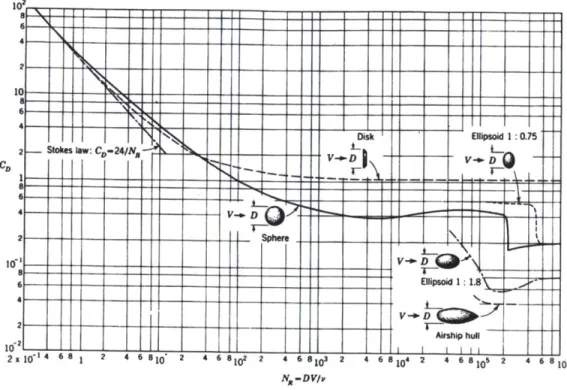
Before applying the above equation, the Reynolds number was determined for the vehicle body as well as the appendages which included the thrusters and antenna. After determining the Reynolds number, the associated drag coefficient was determined for each component using the following figure.
N,-DV/v
Figure 15: Drag Coefficients based on Geometry
Table 3: Reynolds number & Drag Coefficients
Reynolds Number CD
Main Body 1.1OE+06 0.34
Antenna 4.72E+05 1
Thrusters 7.09E+05 1
The equation above was used for the main body and primary appendages to determine the total power required to achieve a given speed. A conservative estimate of 50 percent propulsive efficiency was used throughout the power estimate. The results of the propulsion power estimate are shown in the following figure. The maximum power output per thruster is 400W for a combined propulsion power of 800 W which corresponds to a top speed of approximately 4.5 knots.
Speed and Power Anlysis in Surge
1800 1600 1400 1200 1000 800 600 400 200 0 i W 0 2 -4-Total Power-U-Power Per Thruster
Speed [knots]
Figure 16: Speed & Power Estimates
Finally, the results from the propulsion power estimate were applied to the operating profile to determine the total power for all four thrusters. The propulsion power as a percentage of mission duration was used to calculate the requisite energy for a given mission. Based on the analysis shown below, all four thrusters require 870 W-hr of energy to complete a 3 hour mission.
Table 4: Power Consumption Due to Propulsion
Horizontal Truster (Per Thruster) Vertical Thruster (Per Thr ster)
% Power
Time Required Consumed % Time Required Consumed Consumed At Speed Power Power At Speed Power Power (4 Thrusters) Power [knots] [W] [W/hr Power [knots] [W] [W] [W]
0% 0 0 0 0% 0 0 0.00 0.00 2% 0.5 1 0.01 5% 0.5 0.5 3% 0.08 3, 1 4 0.1 50% 1 1 2.19 4.65 10% 1.5 15 1 10% 1.5 1.5 148% 5.93 15% 2 35 5 10% 2 2 3.51 17.56 35% 2.5 69 24 7% 2.5 2.5 480% 57.61 15% 3 119 18 5% 3 3 5.93 47.40 10% 3.5 188 19 5% 3.5 3.5 941% 56.45 5% 4 281 14 3% 4 4 8.43 44.94 5% 4.5 400 20 2% 4.5 4.5 800% 55.99 Total Power [W] 290
3.1 Hotel Power Consumption
The hotel loads associated with the Didemnum Cruiser remain relatively constant and are significantly smaller than the propulsion loads. Although relatively small, compared to the propulsion loads, detailed accounting of hotel loads is necessary to accurately predict the vehicle's run time. Hotel loads were also categorized by required voltage to account for the 5volt and 12 volt loads. This analysis was also used to size the vehicle's main power supply for both existing and future loads.
Table 5: Estimated Hotel Power
Hotel Loads
4.0 Battery & Power Supply
One of the most crucial components of an AUV is its power source. As battery technology continues to rapidly advance, the number of potential power sources has significantly grown. In the past AUVs were typically powered by Nickel-Metal Hydride or Nickel Cadmium batteries. Nickel based batteries have been a popular power source due to their high discharge capacity and safe charge/discharge characteristics. The primary disadvantage of Nickel based batteries is their low power to weight ration compared to lithium based batteries.
Because weight is a primary concern in AUV design, Nickel based batteries have given way to lithium ion and lithium polymer batteries. Lithium ion batteries are normally housed in metal casings similar to AA, C, and D cell form factors and have a single cell DC voltage of 3.7 V. Although the cell voltage of lithium polymer cells is identical to lithium ion cells, the form factor is significantly different. Lithium Polymer cells, often referred to as "plastic cells", are typically wrapped in aluminum foil and can be combined to form packs of various shapes and sizes. A single Lithium Polymer cell is shown in the figure below. The energy density of Lithium Polymer cells is typically 20-30% greater than traditional Lithium Ion cells.
Figure 17: Lithium Polymer Battery -Single Cell
A primary disadvantage of Lithium based batteries is the safety concerns when charging and
circuitry which limits the maximum and minimum voltage during charge and discharge. Additional protection is commonly incorporated into the battery charger for redundant protection.
In order to achieve voltage and power capacities capable of powering an AUV, several Li-Jon cells must be hard wired using battery holders or spot welding the cells in series and parallel to achieve the desired voltage and current capacity. A similar sized vehicle, Rex 2 used 19 18650 cells in parallel to create a "supercell" and linked 8 supercells in series to form a 30V battery with a capacity of 1.4 KWh. A rendering of Rex 2's battery is shown below in Figure 18(Owens
2009).
Figure 18: Rex II Custom Battery Pack
A custom battery such as the one fabricated for REX II required a significant amount of time to
design and construct and is not easily replaced when the cells reach their end of life.
When selecting a battery consideration must be made for energy storage, discharge capacity, charging rate, and system voltage. In most AUVs, the battery voltage matches the thruster voltage, as thrusters are typically the highest voltage load on the electrical system. Because of this relation, the process of selecting a battery and thrusters was tightly coupled.
4.1 Battery Selection
The final battery selection leveraged the propulsion powering estimate and hotel load estimate to determine the total power consumed by the vehicle during operation. The total power was used to find the threshold value of energy (1020 W-hr) needed to achieve the desired run time of 3 hours. Using the energy requirement as a threshold, three potential batteries were selected and
evaluated from an energy density, volume, and cost perspective. The three batteries options are shown in the figures below.
Figure 19: Battery Pack Options
The first battery option consisted of creating a custom battery pack made of cylindrical 18650 Lithium Ion cells (Left) similar to the cells found in the REX II custom battery pack. The second option required 4 prismatic Lithium Polymer battery packs (Center), linked in parallel to provide the requisite capacity. The final option evaluated was a large Lithium Polymer pack (Right). Both Lithium Polymer packs included battery management cards which allow the voltage of each cell to be monitored during both charge and discharge. Building a custom pack from the
Table 6: Battery Physical Parameters
mAh Kg Cells
Design Cell per Length Width Height Per Cells in in Total Cost
Geometry Type cell [m] [m] [m] cell Parallel Series Cells er cell
Lithium $ Cylindrical Ion 2600 0.018 0.018 0.048 19 6 114 7.00 Lithium $ Prismatic Polymer 12700 0.17 0.135 0.0415 2.27 4 1 4 474.99 Lithium $ Prismatic Polymer 42000 0.272 0.145 0.072 6.25 1 1 1 1,319.90
Table 7: Battery Analysis
Total
Total Total Weight Energy Energy Density
Volume [m3] [kg] Total Cost [kWh] [kWh/m3]
0.0025 5.472 $ 1300.00' 1.10 436.638
0.0038 9.08 $ 1,899.96 1.32 345.361
0.0010 6.25 $ 1,319.90 1.10 1142.137
Note 1: The estimated total cost includes cost associated with purchasing a battery management card as well as assembly costs.
Using the above table, a decision matrix was created to determine the best overall battery option. The five key factors and associated weights used to evaluate the matrix were as follows:
Battery Volume - 2 Total Weight -2 Total Cost - 1 Total Energy -2 Energy Density - 3 Page 135
Table 8: Battery Decision Matrix
Battery Decision Matrix
Volurne 2 2 4 1 2 3 6 0 No fit
Weight 2 2 4 1 2 2 4 1 Low
Cost 1 2 2 1 1 2 2 2 Good
Total Energy 2 2 4 3 6 2 4 3 Excellent
Energy Density 3 2 6 1 3 3 9
Score = Rating * Weight
From the above matrix, the battery with the highest score was the single pack Lithium Polymer pack.
4.2 Battery Housing
Using the modular construction approach allowed the battery to be placed inside a pressure
housing separate from the vehicle computer and electronics. A separate housing reduces
magnetic interference between the Inertial Motion Unit (IMU) and the primary battery which mitigates the compass error seen in previous vehicles. Another advantage of splitting the battery and electronics housings is the ability of the battery to be removed from the vehicle without the need to remove the electronics and vice versa. This aspect of the design was a vital part of achieving a high duty cycle. A fully charged battery pack can easily be exchanged for a depleted pack following several hours of run time with minimal time out of the water.
The battery housing was constructed out of the same schedule 80 CPVC pipe as the electronics housing and uses identical end caps with the only exception being the number of penetrators in both front and rear end caps. The battery front end cap has two penetrators; one for charging and one for supplying power to the vehicle electronics and thrusters. A vent port is also incorporated
housing. The relay on the main breaker is energized using a switch connected through same penetrator as the charging cable using pins one to control the relay.
Figure 20: Battery Housing Figure 21: Main Battery Breaker
5.0
Structural Components
After completing the initial concept design the detailed design was developed and analyzed using various Computer Aided Design and analysis tools
5.1 Vehicle Frame
As the load bearing skeleton of the AUV, the frame was created around the concept of modularity. The frame was designed to provide adequate strength for anticipated loads during routine operations. The highest stress in the structural members is likely to occur during the launch and recover phase. Detailed strength calculations for worst case loading conditions are found in Chapter 8. The frame consists of ring frames that are spaced to accommodate the various portions o f the AUV. Each frame is made from 0.75 inch thick Starboard which is a slightly buoyant and impact resistant plastic. The ring frames were machined using a waterjet and have an outside diameter of 9 inches. The ring frames for the battery and electronics modules have a unique shape compared to the other ring frames. These frames are designed to hold the battery and electronics bottles as low in the vehicle as possible to assist achieving a low center of gravity. The offset inside diameter allows the pressure vessels to sit low in the vehicle and also allows a significantly larger amount of buoyant foam to be located above the pressure vessels which again helps to achieve a low center of gravity as compared to the center of buoyancy. These frames were split at the center to allow access to the electronics and battery pressure housing for maintenance, troubleshooting, and recharging. An example of the split frame is shown below in Figure 22. Both split frames and ring frames are shown in Figure 23.
Split Frame Top
N Split Frame Bottom
Figure 22: Split Frame
Figure 23: Concentric 9" Frames
5.2 Pressure Housing Design
According to the prescribed design philosophy, commercial products were to be used to the maximum extent possible. After reviewing quotes for commercial pressure housings, it was determined that there was little room in the budget to purchase custom manufactured housings at approximately $ 5000.00 per housing. After ruling out commercial housings, custom housings were designed to contain the vehicle electronics and battery.
Before selecting the appropriate housing material, analysis was performed on Aluminum 6061 and CPVC pressure housing designs from a cost and weight perspective. Because pressure housing for a 100 meter depth rating required relatively thing housings, equations governing thin-thin wall cylinders were used for the corresponding materials. The following equation was used to calculate the collapse pressure and required weight of an Aluminum 6061 thin-walled cylindrical pressure vessel subjected to external loading (Baumister 1987):
SKE C (,)3
Where:
Wc = Collapse pressure (psi)
E = Youngs' modulus for Aluminum 6061
t = wall thickness
D = outside shell diameter
K= numerical coefficient depending on L/D and D/t ratios
The K values used to compute the appropriate collapse pressure are based on the following graph. In this case global failure corresponds to N=2, where N is equal to the number of lobes into which the housing collapses. The failure modes are illustrated below in figure X.
200 /00 80 60 40 8 3
8I
.4 06 48 / 2 4 6 8 /0 20 4160 0 /0 200 Va/4,es o/In order to calculate the collapse pressure associated with the CPVC housing, ASTM F480 was applied using the following equation (Rosco Moss Company 2008).
PE =
Where:
Pc: Collapse Pressure (psi)
E: Young's Modulus for PVC Pipe (370,000 psi)
u: Poison's Ratio (0.41)
t: Wall Thickness (in)
Do: Outside Diameter (6.625")
The results of this analysis yields a collapse pressure of : psi
The next step in the analysis compared the weight of the two pressure housings to determine which housing offered the greatest weight savings. In each case a factor of safety of two was applied to the design and a standard OD was set to 6.625 inches. The results of the weight analysis are shown below in Figure 24. From the figure below, we see that aluminum provides a small weight savings at shallow depths. This however is purely from a theoretical standpoint, as the required shell thickness of aluminum at the design depth is less than 1/4 inch, making it difficult to fabricate.
Pressure Housing Weight Comparison
0.6 0.5 o 0.4 - PVC Housing 0.3 cG --- 6061 Aluminum = 0.2 0 0.1 S0 0 100 200 300 400 500 Depth Rating [ft] Note: Factor of Safety =2
Figure 24: Aluminum and PVC Weight Comparison
After completing the weight analysis, the electronics and battery housings were designed using Schedule 80 CPVC for the cylindrical body. Schedule 80, 6" nominal CPVC pipe allows for a factor of safety of 1.82 at a depth of 100 meters and has an acceptable thickness to support fabrication. The inside edge of each end of the cylinder was beveled and cut to a constant inside diameter to create a proper seal for the end cap and O-ring as shown below in Figure 25.
Figure 25: Pressure Housing Beveled Edge
Additional Finite Element Analysis was performed on the CPVC housing to validate the results
based on the ASTM calculation. Results from the FEA Analysis are shown below in Figure 26. The maximum calculated stress from the FEA analysis corresponded to 3114 psi which is well below the CPVC Tensile strength of 7600 psi (Harvel Plastics 2011). Comparisons between the
FEA results and ASTM calculations are shown in
. Detailed drawings of both electronics and battery housings are found in Appendix A.
Table 9: Pressure Housing Strength Analysis
Pressure Housing Strength Analysis
FEA ASTM %
Results Results Difference
Collapse Pressure [psi] 351 282 5% Collapse Depth
Im
243 196 5% Factor of Safety 2.43 1.96 5% Page |43Figure 26: PVC Body FEA Analysis
5.3 Pressure Housing End Caps
The starting material for the Pressure Housing end caps consisted of 2" thick, 6061 Aluminum alloy discs. Aluminum alloy was chosen due to its machinability, resistance to corrosion, and high strength to weight ratio. The end caps were designed to mate with the CPVC pressure housing using a %" O-Ring Seal. The end caps are chamfered to match the beveling on the inside of the CPVC pressure housing to achieve a higher contact surface area between the pressure housing and end caps. The %" O-Rings were chosen due to their resistance to wear and being readily available through common suppliers. The O-Ring glands were sized in accordance
Figure 27: Machining End Cap Using CNC Lathe & Mill
The front and back end caps are nearly identical however; the front end cap has a thicker inside lip to accommodate a double seal vent plug. Another difference between the front and back end caps are the number of bore penetrations on the outside face. These spot-faced through-bore penetrations provide a mating surface for electrical connections. These penetrations are essential to thruster and sensor integration as they allow electrical signals to pass from the sensor through the pressure boundary and interface with the main vehicle computer. Detailed machine drawings for all end caps are included in Appendix A. A Rendered drawing and photo of a completed end cap are shown below in Figure 28.
Figure 28: End Cap as Designed & Built
In addition to sealing the end caps, the vent plug provides two essential functions for the operation of the vehicle. The vent plug allows a vacuum to be drawn prior to use in order to test the O-Ring seal. It also allows the system to be pressurized which allows the end caps to be easily removed. The PREVCO vent plug is based on a SAE #4 bolt with double O-ring seals. A detailed view of the vent plug and required porting instructions are found in Appendix A. The end cap design was validated using FEA analysis shown below in Figure 29.
Figure 29: End Cap FEA Analysis
5.4 Faring, Nosecone & Tailcone
In order to minimize frictional and bluff body resistance, an external faring was fabricated using
9 inch PVC duct. Sections of PVC duct were cut to fit the modules and fixed to the vehicle
using bolted connections at the frame and also by using large diameter pipe clamps. The pipe clamps were also used to secure the vehicle carrying handles located at the bow and the stem of the vehicle. The pipe clamp's quick release mechanism allowed the handles and farings to easily
resistance was selected for the nose and tailcone as impact to these portions of the vehicle are likely to occur.
6.0 Modularity
Previous vehicles including Odyssey IV and REX II were built around a fixed platform, or point design, which allowed little flexibility when mission requirements changed. For these vehicles, adding new equipment was accomplished in two ways. The first way to add additional payload to a fixed platform is to fit the equipment inside an existing void. Because AUV's are typically designed to be as small as possible, there is little room to fit new payload. If payload cannot be added internal to the vehicle, the remaining option is to add the equipment external to the vehicles body or fairings. Adding equipment eternal to the vehicle body has the potential to
significantly alter vehicle characteristics and performance.
For example, REX II, shown below in Figure 30, was recently upgraded with new sensors to facilitate additional research objectives. Because there was little room for new payload, the new sensors were added to the port and starboard sides of the vehicle using custom mounting brackets.
Figure 30: Rex II
body faring would significantly reduce the vehicle's top speed and reduce the overall run time of the vehicle.
The Didemnum Cruiser was built using a module concept. The overall design is broken up into key components (modules) which when put together make up the overall design. The baseline design consists of 5 basic modules. The baseline vehicle can easily accept additional modules to
improve the overall flexibility and capability of the design without significantly changing the overall body type
The modules which make up the baseline design are as follows:
Batteiy Module Electronics Module
Thruster Midbody Module
FWD Thruster Module
AFT Thruster Module
The assembled baseline vehicle is shown below in Figure 33. The baseline vehicle incorporates several features which enable modular construction. The frame sections for the battery and electronics modules incorporate pass-throughs to allow signal and power cables to run from the central computer and power supply to the sensors and thrusters. This feature bypasses the need to alter the vehicle frame when adding additional modules.
While the addition of new modules does not require permanent alterations to the baseline vehicle, adjustments are required to maintain level trim and neutral buoyancy. Trimming weights can easily be added to the threaded rods in the nose or tail sections as well as within the thruster midbody. The nose, tail, and midbody can also be used to add additional buoyant foam to retain a neutrally buoyant system.
Figure 31: Baseline Vehicle
The primary mission set for the Didemnum Cruiser consists is taking still photos of the ocean floor. This is accomplished using a camera system enclosed in a separate module that can easily be added and subtracted from the design. The camera module is shown below in Figure 32
Figure 32: Camera Module
Figure 33: Baseline Vehicle with Camera Module
Page 151
7.0 Computer System
Like other primary components in the design, there were several integration points which needed to be addressed before selecting the appropriate main computer. The entire operation of the vehicle relies on the main computer to process the signals received from the sensors and deliver the appropriate commands to the thrusters.
The first selection criterion for the computer was size. In order to fit inside the pressure housing, a small form factor with a diameter of less than 5.63 inches was required. The PC-104 form factor was selected for the Didemnum cruiser and is mounted inside the pressure housing as illustrated below in Figure 34. The cards are mounted to an ABS frame using plastic standoffs and mounting screws. The card orientation also allows additional cards to be easily added to the stack and provides adequate space to run cabling to the components within the electronics housing.
Unlike Odyssey IV, the Didemnum Cruiser electronics module does not incorporate a circulating cooling medium to provide a heat sink due to the motor controllers being mounted external to the main computer. Because there is still potential to generate heat within the electronics housing, all components selected are the extended temperature versions to minimize the possibility of an overheating casualty.
The maximum range, run time, and duty cycle of the vehicle are functions of efficiency and
power consumption. When selecting the components within the PC104 stack additional
consideration was given to the efficiency and power consumed by each component. Power consumption was one evaluation criterion used to select the PC-104 peripherals. The total power consumption of the PC-104, power supply, serial card, and Ethernet switch is less than 15 Watts.
7.1 Power Supply
The computer is powered using a TRI-M 50W high efficiency power supply. The power supply takes its input from the main battery through a main power relay and provides 5 volt and 12 volt output power on separate pins. The isolated 12 volt and 5 volt outputs are used to power the sensors external to the PC104 stack (Tri-M Engineering 2005). Power is also delivered to the main CPU, Serial Card, and Ethernet switch using the PC104 header . The power supply is
shown below in Figure 35.
Figure 35: Tri-M Power Supply
7.2 CPU
The primary computer, a Lippert COOLl LITERUNNER CLR-LX800, is a small but card with a
500 MHz AMD processor with 256MB of internal RAM. The CPU card includes 2 RS232 serial
ports, 4 USB 2.0 ports, and a 2 high speed Ethernet ports. The CPU is loaded with the LINUX operating system which is used to run the Mission Oriented Operating System (MOOS) for vehicle control. The Primary CPU is shown below in Figure 36.
Figure 36: Lippert COOL LITERUNNER Embedded CPU 7.3 Serial Card
In order to network with the vehicle sensors, a RS232 4 port opti isolated Serial card is also built into the PC 104 stack. The serial card accepts inputs from the AHRS, Depth Sensor, and Micron Altimeter using LINUX drivers. The 4-port serial card is shown below in Figure 37.
7.4 Ethernet Switch
Unlike the other sensors, the camera system connects to the main computer using an Ethernet connection. The 4 port Ethernet switch is used to provide this interface and is shown below in Figure 38.
Figure 38: Parvus Ethernet Switch
8.0 Sensors & Instrumentation
The sensor suite is used to guide and navigate the vehicle in all phases of operation. While surfaced, the Attitude Reference Heading System (AHRS) and Global Positioning System (GPS) receiver are used to navigate the vehicle. Once submerged, the GPS is no longer used, and the vehicle relies on the AHRS for navigation, depth sensor for distance below the ocean surface, and the altimeter determine the distance above the ocean surface.
8.1 Altimeter
To accurately photograph the ocean floor, a precision altimeter is used to find the vehicle's distance from the sea floor. The Altimeter is essentially a small SONAR system that uses sound pulses and their associated returns to detect the altitude above the ocean floor. Operating at a constant distance from the seafloor allows the camera to retain the same focal length from picture to picture and allows the focus to be preset based on the prescribed altitude. The altimeter chosen for the Didemnum Cruiser is the Tritech Micron Echosounder which is shown below in Figure 40.
Figure 39: Tritech Micron Echosounder
Although somewhat costly, the altimeter provides exceptional accuracy and is extremely light weight with a weight in air of only 0.2 kg. The altimeter is interfaced through an RS 232 serial
port and is powered from the common 12V bus (Tritech International Limited 2007). The
Figure 40: Micron Echosounder Placement
8.2 Depth Sensor
The sensor most important to the survival of the vehicle is the depth sensor. Because the AUV would face sudden catastrophic failure should the rated depth be exceeded, it was crucial to incorporate a reliable depth sensor into the Didemnum Cruiser. Many -commercial pressure sensors used for high pressure piping systems are readily available through numerous sources. Although these sensors are low in cost, they require additional potting and system integration which is a time intensive and somewhat expensive process. In this case, a potted, plug and play depth sensor was purchased from Desert Star Systems which is shown below in Figure 41. The underwater housed pressure sensor is rated to 500 PSIA which corresponds to approximately 300 meters of seawater. Not only is the pressure sensor small in size, it has an accuracy of 3 cm which ensures the design depth Of 100 meters will not be exceeded.
I
Figure 41: Desert Star Systems Depth Sensor
Although more expensive than building a custom depth sensor from a commercial pressure gauge, the additional cost was acceptable in this case to reduce fabrication time by an estimated 20 hours. The Depth Sensor is located on the front of the vehicle within the nosecone and is mounted using a starboard bracket and plastic set screws. The placement of the Depth Sensor is shown below in Figure 42.
Figure 42: Depth Sensor Mounting Location
Because the nosecone is free flooded, the pressure inside the nosecone is equal to the hydrostatic pressure at depth. With the depth sensor exposed to sea pressure inside the nosecone, no
additional penetrations in the nosecone were required.