Design and Implementation of Series Elastic Actuation in a Biomorphic Robot Leg by
Nathaniel K. Chan
SUBMITTED TO THE DEPARTMENT OF MECHANICAL ENGINEERING IN PARTIAL FULFILLMENT OF THE REQUIREMENTS FOR THE DEGREE OF
BACHELOR OF SCIENCE AT THE
MASSACHUSETTS INSTITUTE OF TECHNOLOGY FEBRUARY 2007
© 2007 Nathaniel K. Chan
All rights reserved
The author hereby grants to MIT permission to reproduce and to distribute publicly paper and electronic copies of this thesis
document in whole or in part in any medium now know or hereafter created.
/72 //
r4
Signature of Author
Department of Mechanical Engineering January 19, 2007
Certified b
Steve G. Massaquoi Ass c ate Professor of Electrical Engineering and Computer Science and Health Sciences & Technology Thesis Supervisor Accepted by
John H. Lienhard V Professor of Mechanical Engineering Chairman, Undergraduate Thesis Committee
XVMVES
I
`--MASSACHUSETTS INSTITUTE OFTECHNOLOGYJUN 2
i
2007
LIB
', • -,
,
• J '• " l . ..Design and Implementation of Series Elastic Actuation in a Biomorphic Robot Leg by
Nathaniel K. Chan
Submitted to the Department of Mechanical Engineering in Partial Fulfillment of the Requirements for the Degree of
Bachelor of Science in Mechanical Engineering
ABSTRACT
Fluid, efficient, robust bipedal locomotion is hard by some approaches. Today's most advanced bipedal robots require flat and level floors, but are still prone to trips and falls. They have trouble interacting with objects in their surroundings, and adapting to them. We think that new approaches may make bipedal control easier. The following work details the design of the BOB (Bag of Bones) biomorphic robot leg that is a continuation of an effort to achieve a better understanding of the sensorimotor neurocontrol of locomotion, particularly in humans. Such an understanding will not only lead to robots that move as well or better than people while being easier to control, but will also enable powerful therapies for ataxia patients.
One of the main design requirements for BOB was to incorporate series elastic actuation, but with hobby servo motors as the power source. The use of hobby servos was intended to keep costs low, as was the extensive use of off the shelf parts whenever possible. With the recent advances in hobby servo motors, it was expected that reasonable if not high performance would be possible.
The specific contribution of this work includes the entire series elastic actuation system powered by servo motors. The elements of the actuation system include circular servo horns, wire rope used in loops, turnbuckles, and series elastic elements that use compression springs in extension.
It was found that the knee joint can flex from 0 to 90 degrees and back in about 0.7 seconds. Similarly, the ankle cycled from approximately 20 degrees of extension to approximately 35 degrees of flexion in about 0.7 seconds. These performance figures indicate that the gearing ratios at the knee and ankle are appropriate and that the current design is sufficiently powered for walking.
Thesis Supervisor: Steve G. Massaquoi
Title: Associate Professor of Electrical Engineering and Computer Science and Health Sciences & Technology
Acknowledgments
In my early days at MIT, I had Gill Pratt as my TA for 6.001. He would sometimes mention the work he was doing in the Leg Lab. Ever since then, I've been interested in walking robots, and I cannot think of a more perfect way to finish my undergraduate time than with this project. For this, I must thank Steve Massaquoi for such a fantastic opportunity. The memories
of talking shop with him at all hours of the day will not be forgotten.
Ron Wiken of The Infrastructure Group deserves special thanks for the unique environment he has setup at CSAIL. Not only was I spoiled for life after one look at his office, but his knowledge and experience are a priceless asset to the lab. He has saved me an inordinate amount of time, and always with a smile.
I am indebted to my family for their support, and especially my mother Pheabe for her prayers and understanding when the going got tough. This work is dedicated to her.
Table of Contents
Introduction
...
Previous Bipedal Robots
...
Desian of BOB
...
3.1 Overview ...
3.2
Skeletal Framework
...
3.3 Actuator System
...
3.3.1 Servo Horn
...
3.3.2 Turnbuckle
...
3.3.3 Series Elastic Elements
...
...
3.3.4 Pulley W heels
...
3.4 Passive Elasticity
...
4. Performance
...
5. Future
W
ork
...
Appendix A
...
References
...
...
5
5
7
7
9
10
10
11
12
15
16
17
17
20
21
1.
Introduction
Fluid, efficient, robust bipedal locomotion is hard by some approaches. The natural world is deceiving in its elegance, especially when it comes to walking and running. Today's most advanced bipedal robots require flat and level floors, but are still prone to trips and falls. They have trouble interacting with objects in their surroundings, and adapting to them. The following work details the design of a biomorphic robot leg that is a continuation of an effort to achieve a better understanding of the sensorimotor neurocontrol of locomotion, particularly in humans. Such an understanding will not only lead to robots that move as well or better than people, but will enable powerful therapies for ataxia patients.
2. Previous Bipedal Robots
There has been much interest in bipedal locomotion in the past, and the walking robots that have been developed can be categorized as either active or passive. Passive walkers are powered solely by gravity. A passive walker with an actuated ankle has also been developed, though it remains underactuated [Tedrake, 2005]. The serious limitation of such walkers is that they are necessarily periodic, while locomotion in natural environments is never so periodic.
Much progress has been made with active bipeds, with several robots being introduced by companies such as Sony (SDR) and Honda (Asimo). The latest version of Asimo is even technically capable of running, with both feet off the ground for 0.8 seconds. Robots such as Asimo are the result of multi-million dollar development efforts, yet they still perform only modestly and with very strict constraints on the operating environment. Asimo's zero moment point (ZMP) control algorithms aims to achieve balance control over the entire gait phase which is unnecessarily conservative and not robust to disturbances [Hoffman, 2006].
One approach to overcoming such limitations has been to look to nature for inspiration. One of the most important features of natural actuators like muscles is that they have elasticity, which de-emphasizes the rigid and well defined position control requirements of ZMP algorithms. Pioneering work done at the MIT Leg Lab [Pratt et al, 1997] included the use of series elastic actuators that were very robust to external disturbances. Several robots were built using such actuators, one of which is shown in Figure 1.
Figure 1: Planar biped known as Spring Flamingo with series elastic actuators. More
pictures and videos can be found at the Leg Lab homepage: http://www.ai.mit.edu/projects/leglab/
It follows that just as actuators that more closely resembled muscles allowed robots like Spring Flamingo to walk more naturally, taking inspiration from nature in the actual control algorithm of bipeds might result in even better locomotion. This idea has so far resulted in a model of cerebrocerebello-spinomuscular interaction in human walking [Jo, 2006], which has been validated in simulation. The motivation behind the construction of the BOB (Bag of Bones) biomorphic robot leg was to validate this model with a physical prototype. Following in
the footsteps of the Leg Lab, one of the main design requirements for BOB was to incorporate series elastic actuation, but with hobby servo motors as the power source. The use of hobby servos was intended to keep costs low, as was the extensive use of off the shelf parts whenever possible. With the recent advances in hobby servo motors, it was expected that reasonable if not high performance would be possible.
3. Design of BOB
3.1
Overview
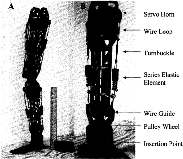
Figure 2 A shows the leg and its scale. Figure 2 B shows a close-up of the lower leg.
Servo Horn
Wire Loop
Turnbuckle
Series Elastic
Element
Wire Guide
Pulley Wheel
Insertion Point
Figure 2 A: The unpowered leg posed in a standing position. Foot long ruler used for
scale. B: Labeled components in servo actuation system with series elastic elements
All joints are actuated by high torque hobby servo motors. One can be most clearly seen and the top of Figure 2 B, with one servo on the front and one on the back of the leg. In the
upper leg, there is a pair of servos front and back. Each servo powers both flexion and extension. At both joints, each servo motor is connected to the joint to be powered using the same componentry, thus achieving a modular design that can be scaled as needed.
Work on the basic skeletal framework and selection of servo motor was already done at the onset of this project. The specific contribution of this work includes the entire series elastic actuation system powered by servo motors. The elements of the actuation system include circular servo horns, wire rope used in loops, turnbuckles, and series elastic elements that use compression springs in extension.
Circular aluminum servo horns are used to anchor wire ropes and provide a constant moment arm as a horn rotates. Joint torque at the knee, for example, is generated by tension in the wire rope which is anchored to an insertion point in the lower leg. The novel feature of this actuation system is the addition of elastic elements in series between the servos and joints. Series elasticity is inspired by the elasticity inherent in muscles and is particularly amenable to neuromorphic control, which relies on muscle-like actuators.
All wire rope is low stretch coated steel cable rated for 90 lb breaking strength. Crimps are used to create wire loops. Though the servo motors are not capable of generating 90 lbs of tension, it was found that crimps significantly degrade the strength of the wire, so doubling up the wire into loops lowered the tension in each individual segment of wire while allowing for the same wire thickness. Retaining the wire thickness is convenient because crimps for even slightly larger gauge wire rope are not readily available. Loops are connected to each other with bolt and nut assemblies that compress the two loops between a pair of washers.
3.2 Skeletal Framework
The frame of the leg and ankle are made of laser cut delrin pieces fastened with off the shelf nylon screws and spacers. The foot is made of ABS, which is more compliant and easier to thermoform into a shape that has some natural compliance. However, ABS is fairly low friction, and thus the foot will benefit in the future from an application of a material with more grip at the contact patches. This first iteration of the foot was thermoformed by hand, so the exact contour will be difficult to replicate. Once a contour has been settled upon, a thermoforming method with better repeatability will be useful.
Around each joint are pulley wheels which redirect the wire ropes and act to enforce a constant moment arm through most of the range of motion. At the extreme of flexion at the knee, the wire rope does lose contact with the pulley wheel, but so far there have been no problems with the wire re-engaging the pulley wheel when the joint is extended.
Each joint is a planar pivot consisting of a hardened steel shaft freely rotating in self lubricating bronze bushings. The free shaft eases assembly and disassembly. At the knee, there is a hard stop built into the upper leg that prevents hyperextension of the lower leg. Right above each joint are wire guides on the front and back that allow the wire loops to pass over and engage the pulley wheels below. Presently, these wire guides are off the shelf plastic bushings that are placed end to end on a shaft that spans the inner width of the limb segment.
It has been observed that on occasion, the wire ropes that run over the gaps in between these bushings can become lodged in between and create an excessive amount of friction. In future designs, this can be alleviated by making the wire guide out of one piece of aluminum, for instance. The extra weight from such an aluminum sleeve would be negligible.
3.3 Actuator System
3.3.1 Servo Horn
The design of the actuation system will now be detailed starting with the servo horn. The circular aluminum horn is an off the shelf part made specifically to mate with the brand of servos used. Their diameter makes them well suited to placing servos closely side by side as they do not interfere with each other. They are also very close in size to the pulleys that are used to redirect the wire rope around the knee joint, thus providing an almost 1:1 gear ratio. Aluminum is easily machined, which simplifies the drilling of the through holes which are used to loop the wire rope through the horn. Figure 3 shows an installed servo horn.
Figure 3: Circular aluminum servo horn
A loop of wire rope runs up each side of the horn and around the top to the anchor point on the other side of the horn. The black delrin pieces on the top and bottom of the horn are not needed to keep the wire rope on the horn during operation, but do help in the installation of the
wire loops. They are fastened to the servo horn with super glue. Epoxy may be a better solution as the super glue bond has been observed to fail, potentially due to dirty surfaces of the parts.
A potential drawback to this design is the sharp edge that remains around the holes that the wire ropes are threaded through. The sharp edges are due to drilling through the aluminum, and on the outside can be deburred easily. The edges of the drilled holes on the inside of the servo horn are much more difficult to reach with traditional deburring tools. So far, deburring only the outside edge has been sufficient to prevent undue stress on the wire rope since most of the tension is borne by that edge. If, over time, it becomes clear that the inside edge needs to be dulled, it is possible to take abrasive thread and run it around the inside edge. This would be time consuming.
3.3.2 Turnbuckle
In Figure 3, turnbuckles can be seen below the servo horn. They greatly aid in the installation and tensioning of the wire loops and elastic elements. The front and back sets of servos are slightly different distances from the joint to make the necessary clearances at the extremes of the motion range. Turnbuckles of different lengths are used on the front and back to make up for that distance. This means that the wire loops around the servo horns and around the insertion points are kept as short as possible to maximize the space for elastic elements and turnbuckles. The only potential drawback to turnbuckles is that they take up space and/or limit range of motion since they cannot bend around pulley wheels or servo horns. This can complicate the routing of wire loops and elastic elements in compact spaces like the hip. If necessary, switching to even smaller turnbuckles would help mitigate space constraints.
3.3.3 Series Elastic Elements
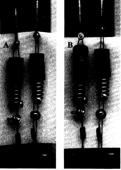
The most novel parts of the actuation system are the elastic elements that can be seen in Figure 4.
Figure 4 A: Series elastic elements at rest. The only "preload" tension in the system is
generated by the very weak springs inside the plastic spring caps. B: Servo motor (towards top of figure) is applying tension to the series elastic element on the right, thus shortening the stiff spring. The displacement of that spring is equal to the displacement of the weak spring in the series elastic element on the left, thus taking up the slack on the
side not transmitting tension to the joint.
Each series elastic element is comprised of two compression springs put end to end. A plastic coupler constrains each spring at the junction, while still allowing wire loops to pass through the middle. One wire loop (coming from the top in Figure 4) passes through the two
compression springs and coupler and is anchored around a bolt to support tension upwards. Bolts are used as they are readily available in the appropriate length, the bolt head keeps it from slipping off the end of the spring, and the threads grip the wire loop well. The other wire loop from the bottom passes through the assembly and anchors to a custom end cap that allows the other wire loop to pass freely. Thus the two compression springs effectively become an extension spring in the same manner as a drawbar spring.
At rest, the weak spring is completely collapsed, and is the only source of tension. Only when the servo horn rotates and applies tension to one side is the stiff spring engaged. The effective stiffness of the side under tension is only the stiffness of the large spring since the weak spring is completely collapsed. On the other side, tension is reduced, and slack would develop if the weak spring were not in place to extend by exactly the displacement of the stiff spring on the other side. This design keeps the tension in the wire loops low at rest, thus reducing the radial load on the servo motor shaft bearings and avoiding premature wear.
The stiffness of the big spring was initially determined from a basic static loading analysis. Further studies into the dynamics of the leg may call for a different stiffness for optimal performance. This would be easily accommodated by replacement of the stiff spring. The goal of the current design was to have one leg support at the very least the weight of the other leg without the load causing too much flexion at the knee. As each leg weighs approximately 4 pounds, the 12 inch moment arm of the upper leg gives a total knee joint torque of 48 pound inches in the worst case scenario of a deep knee bend with the upper leg horizontal. Each of the 4 servo motors for the knee must therefore support 12 pound inches. The 0.5 inch radius of the
servo horn gives 24 pounds of tension. The spring chosen for the current design has a spring constant of 363 pounds per inch which, under 24 pounds of force, displaces 0.07 inches. This is
about 3 degrees of angular displacement with the 1 inch diameter pulley wheels. 3 degrees of angular displacement gives less than an inch of "sagging" at the hip under this load, which was deemed acceptable.
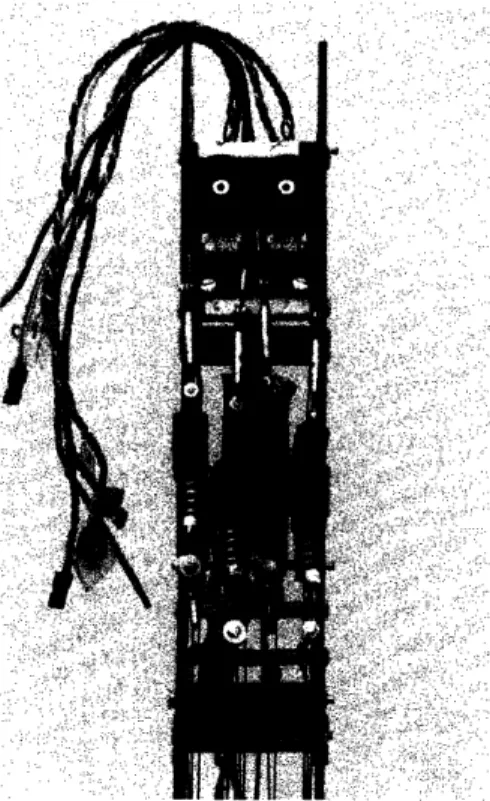
The main drawback to this design is that it takes space because it cannot bend. A torsion spring in the servo horn, for example, would be much more compact, but no conventional torsion springs surveyed are sufficiently stiff. It may be possible in the future to design a more appropriate torsion spring that utilizes flexures for high stiffness and small displacements. The series elastic elements also take up width, which limits how closely the servo motors can be placed side by side. Currently, the interference between elastic elements of adjacent servo motors is slight, and a flexible woven nylon sleeve placed over one of the elements is sufficient to ensure that they slide by each other. This interference can be seen in Figure 5 below.
Figure 5: The interference of adjacent elastic elements is evidenced by the displacement of the turnbuckles above them. The woven nylon sleeve can be seen covering one elastic
If future designs call for stiffer springs that are larger is diameter, this nylon sleeve may not be sufficient, and the servo motors will have to be moved apart.
If compactness in length is particularly important, it is possible to trade off extra width by placing one compression spring within the other. Such a concentric assembly would behave similarly to the current design, except that the weak spring would not necessarily have to be collapsed completely before the stiffer spring is engaged.
3.3.4 Pulley Wheels
The elastic elements are finally connected to a wire loop that is anchored to an insertion point in the section of the limb that is being powered. In Figure 6, the ankle joint is shown, with the insertion point for the foot at the bottom.
The wire loops around the ankle joint run around pulleys that are roughly double the radius of the servo horns, thus creating a 2:1 gear reduction. The ratio can be optimized for speed or torque by changing the size of these pulley wheels. Of the two wire loops running from each servo horn, one wire loop run runs over the front of a pulley wheel and the other wire loop runs over the back before anchoring around the insertion point. This allows each servo to power both flexion and extension.
3.4 PASSIVE ELASTICITY
There is one additional elastic element in the leg which is passive, and it is identical to the other elastic elements connected to the servo motors. Instead of a servo horn, it is affixed to a crossbar. The passive elastic element and the mounting crossbar can be seen below in Figure 7.
Figure 7: Passive elastic element mounted to fixed crossbar in the upper leg. The initial displacement of the weak spring can be seen, and determines the angle at which the
As it is currently installed, the stiff spring engages the knee joint beyond about 80 degrees of flexion. This angle can be arbitrarily set by changing the initial displacement of the weak spring. The passive elastic element was included to aid the knee in extending from a deep knee bend. This design does this without affecting the overall weight and joint stiffness during walking.
4. PERFORMANCE
The performance of the leg was tested by testing the ankle and knee joints separately. In a standing (but otherwise unloaded) position, the knee was commanded to move from 0 degrees of flexion to approximately 90 degrees and back. At the minimum servo motor supply voltage of 4.8 volts, the knee took approximately 0.9 seconds to complete the cycle. At the maximum specified voltage of 7.4 volts, the cycle took approximately 0.7 seconds.
The ankle was similarly tested with the knee locked in the upright position. Loaded only by the weight of the leg, the ankle was tested by cycling from approximately 20 degrees of extension to approximately 35 degrees of flexion. At 4.8 volts, the ankle completed the cycle in
about 0.9 seconds. At 7.4 volts, the cycle was completed in 0.7 seconds. These performance figures indicate that the gearing ratios at the knee and ankle are well suited and that with just a little coordination of the two joints, a deep knee bend can be achieved. These figures also suggest that the current design should be sufficiently powered for walking.
5. FUTURE WORK
Significant progress has been made in the design of a biomorphic robot leg that leverages the increased power output of new servo motors and low cost of off the shelf components. There still remains much work to be done, and it can be divided into design considerations that are immediately relevant and those for the future.
By far, the most important element missing from the current design are feedback sensors. Rotary joint angle sensors, foot contact sensors, inclinometers, and accelerometers are all potentially useful feedback sensors to have mounted on the leg. Currently, the most useful feedback signal is joint angle. Plans for mounting a hollow shaft potentiometer on the outside of the knee and ankle joints are already underway. External mounting of the potentiometer requires a freezing of the joint shafts to the lower leg, which will be accomplished by a press fit of the shaft to the lower leg delrin plates. Foot contact pads should be kept in mind during the design of a foot with higher traction. Inclinometers and accelerometers should be simple to mount if needed.
The other design consideration for the immediate future is adequate internal clearance for additional and/or larger passive elastic elements. Currently, the placement of the nylon standoffs used for internal bracing of the upper leg leaves just enough clearance for a passive elastic element that is the same in size as the series elastic elements. Widening the middle width of the upper leg will allow for repositioning of the nylons standoffs and allow for more internal clearance. This step is already being implemented in the upper leg. See Appendix A for a solid model rendering of the new skeletal framework. The performance of the current leg design does not indicate the need for passive elasticity at the ankle joint, but if that becomes necessary in the future, the lower leg will also benefit from widening and repositioning of nylon standoffs.
The rest of the design considerations for the future will rely on feedback from further testing and specific performance goals. For example, while the current design has sufficient performance for walking, it may be underpowered for running. The series elasticities may also not be the optimal stiffness. The simplest way to add more power is to increase the number of servo motors per joint. The bank of servo motors at the top of the upper leg, for instance, can be
made wider to include not four but six servo motors. The gearing ratio can also be changed by changing the diameter of pulley wheel around a joint, and optimized for either speed or torque. The stiffness of the series elastic elements can be changed by swapping in springs with different spring constants.
References
[Hoffman, 2006] Robust Execution of Bipedal Walking Tasks From Biomechanical Principles. Ph.D. Thesis, MIT
[Jo, 2006] S. Jo, S. Massaquoi, A model of cerebrocerebello-spinomuscular interaction in the sagittal control of human walking, Biological Cybernetics
[Pratt et al., 1997] J. Pratt, P. Dilworth, G. Pratt, Virtual Model Control of a Bipedal Walking Robot,
Proc. International Conference on Robotics and Automation
[Tedrake, 2004] Applied Optimal Control for Dynamically Stable Legged Locomotion. Ph.D. Thesis, MIT