Design and Prototyping of a Low-cost Portable Mechanical Ventilator
by
Stephen K. Powelson
SUBMITTED TO THE DEPARETMENT OF MECHANICAL ENGINEERING IN PARTIAL FULFILLMENT OF THE REQUIREMENTS FOR THE DEGREE OF
BACHELOR OF SCIENCE IN MECHANICAL ENGINEERING AT THE
MASSACHUSETTS INSTITUTE OF TECHNOLOGY JUNE 2010
C 2010 Stephen K. Powelson. All rights reserved. The author hereby grants to MIT permission to reproduce
and to distribute publicly paper and electronic copies of this thesis document in whole or in part in any medium now known or hereafter created.
r
ARCHIVES
MASACHSETS NS E OF TECHNOLOGYJUN 30 2010
LIBRARIES
fNl Signature of Author:Department of Mechanical Engineering May 23, 2010 Certified by:
Alexander H. Slocum Pappalardo Professor of Mechanical Engineering Thesis Supervisor Accepted by:
4:' John H. Lienhard V
ofessor of Mechanical Engineering Chairman, Undergraduate Thesis Committee
Design and Prototyping of a Low-cost Portable Mechanical Ventilator
Abdul Mohsen Al Husseini', Justin Negretel, Stephen Powelson', Amelia Servi', Alexander Slocum',Jussi Saukkonen2
'Massachusetts Institute of Technology, Department of Mechanical Engineering 2Boston University, School of Medicine
Abstract
This paper describes the design and prototyping of a low-cost portable mechanical ventilator for use in mass casualty cases and resource-poor environments. The ventilator delivers breaths by compressing a conventional bag-valve mask (BVM) with a pivoting cam arm, eliminating the need for a human operator for the BVM. An initial prototype was built out of acrylic, measuring 11.25 x 6.7 x 8 inches (285 x 170 x 200 mm) and weighing 9 lbs (4.1 kg). It is driven by a stepper motor powered by a 14.8 VDC battery and features an adjustable tidal volume of up to 900 mL, adjustable breaths per minute (bpm) of 5-30, and inhalation to exhalation time ratio (i:e ratio) options of 1:2, 1:3 and 1:4. Tidal volume, breaths per minute and i:e ratio are set via user-friendly knobs, and the settings are displayed on an LCD screen. The prototype also features an assist-control mode and an alarm to indicate over-pressurization of the system. Future iterations of the device will be fully calibrated to medical standards and include all desired ventilator features. Future iterations will be further optimised for low power-consumption and will be designed for manufacture and assembly. With a prototyping cost of only $420, the bulk-manufacturing price for the ventilator is estimated to be less than $100. Through this prototype, the strategy of cam-actuated BVM compression is proven to be a viable option to achieve low-cost, low-power portable ventilator technology that provides essential ventilator features at a fraction of the cost of existing technology.
Keywords: Ventilator, Bag Valve Mask (BVM), Low-Cost, Low-Power, Portable and Automatic
1.
IntroductionRespiratory diseases and injury-induced respiratory failure constitute a major public health problem in both developed and less developed countries. Asthma, chronic obstructive pulmonary disease and other chronic respiratory conditions are widespread. These conditions are exacerbated by air pollution, smoking, and burning of biomass for fuel, all of which are on the rise in developing countries" 2 Patients with underlying lung disease may develop respiratory failure under a variety of challenges and can be supported mechanical
ventilation. These are machines that mechanically assist inspiration and exhalation, a
3
process referred to as artificial respiration While the ventilators used in modem hospitals in the United States are highly functionally and technologically sophisticated, their acquisition costs are correspondingly high (as much as $30,000). High costs render such technologically sophisticated mechanical ventilators prohibitively expensive for use in resource-poor countries. Additionally, these ventilators are often high-maintenance, requiring costly service contracts from the manufacturer. In developing countries, this has
My contributions to the low-cost ventilator project were principally in the areas of
mechanical design and construction.
The project was started as a part of the class
2.75:
Precision Machine Design. In the
beginning phase of the project, during group brainstorming we decided to actuate a
bag-valve-mask to make our low-cost ventilator. While considering different actuation mechanisms I
suggested making a rolling-contact cam; as a group we then worked out the specifics of this cam
mechanism. Once this cam strategy was decided, I was responsible for the Solidworks modeling
and much of the construction of the first cam-compression proof-of-concept rig. After the rig
showed that cam compression was viable, I created a Solidworks model of the first prototype.
We constructed this first prototype during the latter half of the fall semester. I was responsible
for much of the mechanical construction while other group members were responsible for
electronics and programming of the device.
During the spring semester, 2.75 was continued as the class 2.752. During this semester,
we sought to improve our design to build a fully-functioning prototype. After much
brainstorming of driving mechanisms, we opted to use a double-ended stepper motor driving
geared cams as our actuation mechanism. I was responsible for the Solidworks modeling of this
new prototype, and later responsible for the majority of the mechanical construction. Once the
prototype was built, we realized the cam needed to be optimized for maximum compression.
After exploring several ideas, I made necessary modifications and tested the prototypes
performance with a bench-level experiment.
I was additionally responsible for all of the Solidworks modeling of the DFMA concept
of the ventilator. This model is still a work-in-progress. Finally, I was responsible for writing
most of the mechanical design sections of our final paper.
led to practices such as sharing ventilators among hospitals and purchasing less reliable refurbished units. Since medical resources in these countries are concentrated in major urban centers, in some cases rural and outlying areas have no access at all to mechanical ventilators. The need for an inexpensive transport ventilator is therefore paramount.
In the developed world, where well-stocked medical centers are widely available, the problem is of a different nature. While there are enough ventilators for regular use, there is a lack of preparedness for cases of mass casualty such as influenza pandemics, natural disasters and massive toxic chemical releases. The costs of stockpiling and deployment of state-of-the-art mechanical ventilators for mass casualty settings in developed countries are prohibitive. According to the national preparedness plan issued by President Bush in November 2005, the United States would need as many as 742,500 ventilators in a worst-case pandemic. When compared to the 100,000 presently in use, it is clear that the system is lacking4.
One example of this shortage occurred during Hurricane Katrina, when there were insufficient numbers of ventilators 5 , and personnel were forced to resort to manual BVM ventilation. Measures to improve preparedness have since been enacted. Most notably the Center for Disease Control and Prevention (CDC) recently purchased 4,500 portable emergency ventilators for the strategic national stockpile 7 . However, considering the low number of stocked ventilators and their currently high cost, there is a need for an inexpensive portable ventilator for which production can be scaled up on demand.
Prior Art
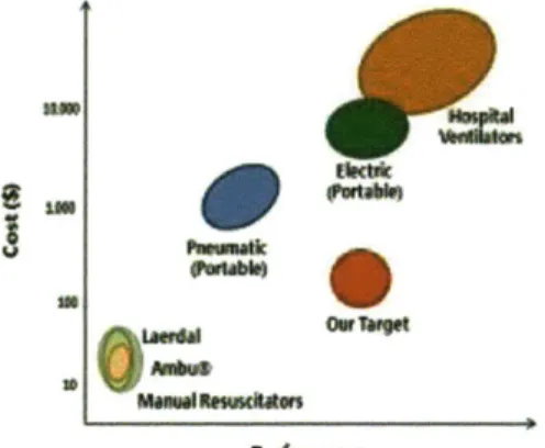
While many emergency and portable ventilators are on the market, an adequate low-cost ventilator is lacking. A low-cost-performance distribution is depicted in Figure 1 with manually operated BVMs on the low end of cost
and performance, and full-featured hospital ventilators on the other extreme. The middle section of the chart includes the existing portable ventilators which can be broadly categorized as pneumatic and electric. Pneumatic ventilators are actuated using the energy of compressed gas, often a standard 50 psi (345 kPa) pressure source normally available in hospitals. These ventilators have prices ranging from $700-1000. This category includes products such as the VORTRAN Automatic Resuscitator (VARTM), a single patient, disposable resuscitator, and the reusable Lifesaving Systems Inc.'s Oxylator, 0-Two CAREvent@ Handheld Resuscitators and Ambu@ Matic. However, these systems cost an order of magnitude more than our target price and depend on external pressurized air, a resource to which our target market may not have access.
0Kt6*
how"c*w
Figure 1: Cost performance distribution of ventilators
Electric ventilators are capable of operating anywhere, and thus are not bound by this constraint. Ventilators of this type such as
CareFusion LTV@ 1200 were the choice of the CDC for the Strategic National Stockpile. The LTV@ 1200 weighs 13.9 lbs (6.3 kg) and includes standard features as well as the capability to slowly discontinue or wean off mechanical ventilator support. Its complexity elevates its cost to several thousands of dollars, an order of magnitude above our target retail price.
The United States Department of Defence has also developed several rugged, portable electric ventilators. One such ventilator is the Johns Hopkins University (JHU) Applied Physics Laboratory (APL) Mini Ventilation Unit (JAMU), which weighs 6.6 lbs (3.0 kg), measures 220 cubic inches (3,600 cubic cm) and can operate up to 30 minutes on a battery. This device was patented by JHU/APL, and licensed to AutoMedx. The commercial device features single-knob operation. Its simplicity comes with a compromise, as the tidal volume, breath rate and other parameters cannot be adjusted by the user, making it not suitable for many patients who cannot tolerate the fixed tidal volume, rate or minute ventilation. It also cannot be operated for long periods in a resource-poor environment. Additionally, with a price tag over $2000, it
costs several times more than our target price. Another device, the FFLSS, weighs 26.5 lbs (12 kg) and is capable of one hour of operation powered by a battery. It also includes additional physiologic sensors, and fits in a standard U.S. Army backpack 8 . While these devices are functionally adequate, their compressors require high power which limits battery life. In addition, their many pneumatic components are costly and are not easily repairable in a resource-poor environment.
Medical Device Requirements
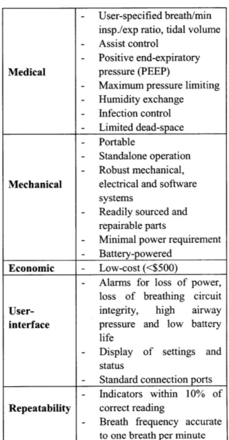
In light of the aforementioned constraints, a set of mechanical, medical, economic, user-interface and repeatability functional requirements were developed. These include the ASTM F920-93 standard requirements9, and are summarized in Table 1.
Table 1: Device functional requirements
- User-specified breath/min
insp./exp ratio, tidal volume
- Assist control
- Positive end-expiratory Medical pressure (PEEP)
- Maximum pressure limiting
- Humidity exchange - Infection control - Limited dead-space - Portable - Standalone operation - Robust mechanical,
Mechanical electrical and software systems
- Readily sourced and
repairable parts
- Minimal power requirement
- Battery-powered Economic - Low-cost (<$500)
- Alarms for loss of power,
loss of breathing circuit
User- integrity, high airway
interface pressure and low battery life
- Display of settings and
status
- Standard connection ports
- Indicators within 10% of Repeatability correct reading
- Breath frequency accurate
to one breath per minute
2.
Device Design Air Delivery TechniqueTwo main strategies were identified for the ventilator's air delivery system. One strategy uses a constant pressure source to intermittently deliver air while the other delivers breaths by compressing an air reservoir. The latter approach was adopted as it eliminates the need for the
continuous operation of a positive pressure source. This reduces power requirements and the need for expensive and difficult to repair pneumatic components.
Whereas most emergency and portable ventilators are designed with all custom mechanical components, we chose to take an orthogonal approach - by building on the inexpensive BVM, an existing technology which is the simplest embodiment of a volume-displacement ventilator. Due to the simplicity of their design and their production in large volumes, BVMs are very inexpensive (approximately $10) and are frequently used in hospitals and ambulances. They are also readily available in developing countries. Equipped with an air reservoir and a complete valve system, they inherently provide the basic needs required for a ventilator.
The main drawback with BVMs is their manual operation requiring continuous operator engagement to squeeze the bag. This operating procedure induces fatigue during long operations,
and effectively limits the usefulness of these bags to temporary relief. Moreover, an untrained operator can easily damage a patient's lungs by over compression of the bag. Our methodology, therefore, was to design a mechanical device to actuate the BVM. This approach results in an inexpensive machine providing the basic functionality required by mechanical ventilator standards.
Compression Mechanism
BVM compression can be achieved with linear actuation (e.g. lead screw, rack and pinion or crankshaft), radial actuation (e.g. noose), or rotary actuation (e.g. cam). The linear actuation concept was quickly rejected because the necessary linear bearings add excessive cost, complexity and bulk to the actuator. The radial compression concept was tested but found to be inefficient. This is because the bag has a high-friction exterior so a compression belt does not easily slide along the surface. This can be
remedied with a roller chain in place of a belt. However, rollers introduce new problems such as pinching. The bag is also not designed for radial actuation and such actuation produces instabilities that result in non-linear compression. In contrast, radial actuation as achieved with a cam mimics the hand motion for which the bag is designed. It is a compact design and employs rolling contact with the bag, thereby reducing frictional losses between the actuator and the bag. This concept was thus pursued.
Cam Concept
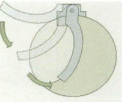
The cam concept utilizes a crescent-shaped cam to compress the BVM. This motion allows smooth, repeatable deformation to ensure constant air delivery (Figure 2). As it rotates, the cam makes rolling contact along the surface thus achieving high-efficiency power transmission. By controlling the angle of the cam, the amount of air volume delivered can be accurately controlled. The cam mechanism was found to be the most space and energy efficient of the compression methods we considered.
Figure 2: Sketch of cam actuator
3.
Prototype DesignFirst Prototype Design
The first prototype featured a DC motor with a planetary gearbox (model PK51 from robotmarketplace.com) coupled to the cam. The enclosure's frame consisted of four vertically
mounted sections of 1/2" (12.5 mm) clear acrylic,
with interlocking mates. This prototype was designed for use with an AmbuTM BVM. The two inner sections (ribs) have U-shaped slots made to conform to BVM's surface contour, while the end sections feature openings to accommodate the BVM's valve neck and oxygen reservoir.
Second Prototype Design
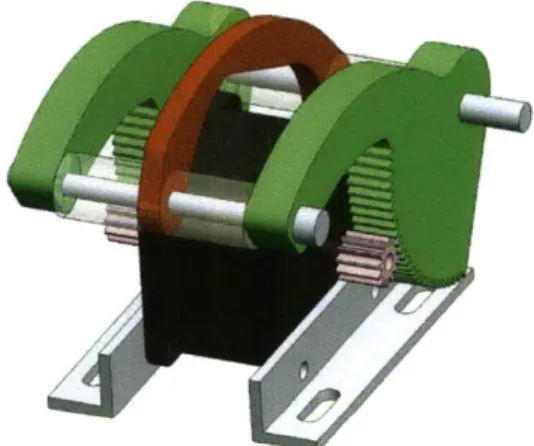
The DC motor used for the first prototype did not deliver enough torque to achieve adequate volume delivery. Therefore, a second prototype was constructed with the goal of improving performance with increased torque output. Changes in the cam design and driving mechanism were instrumental in improving compression performance. The cam assembly in this prototype features two geared nylon cams driven off of pinions mounted onto the shafts of a double-shafted stepper motor (Figure 3).
Figure 3: Model of the cam assembly with motor The radius of curvature of the cams approximately matches that of the BVM, giving a mostly rolling-contact compression. The cam arms are laser cut and their teeth are modulus 1 with a pitch diameter of 96 mm. A double-ended stepper motor drives each of these cam arms with a 12 tooth pinion mounted on each end of the shaft. This gearing allows for a reduction of 8 to 1. Centered between the two geared cam arms is a rib which protrudes above the geared
cams on either side. This central rib makes first contact with the BVM. As the BVM is designed to be squeezed at the center of the bag, this central rib greatly reduces the BVM's resistance to compression.
This cam assembly was mounted in an acrylic compartment similar to that of the first prototype. However a few notable changes to the compartment were implemented. The second prototype was designed for use with a LaerdalTM BVM. This BVM was selected because it features an exhale valve and mask that can be detached from the bag. This feature allows the valve and mask to be placed at the patient end of an extension tube. With the second prototype, the hinge location was shifted from the top edge of the box to the center, in plane with the center axis of the BVM. This allows for better lid closing and constraint of the BVM. Moreover, alterations were made to the central ribs that constrain the BVM in order to minimize friction during compression. The second prototype is shown in Figure 4.
Testing
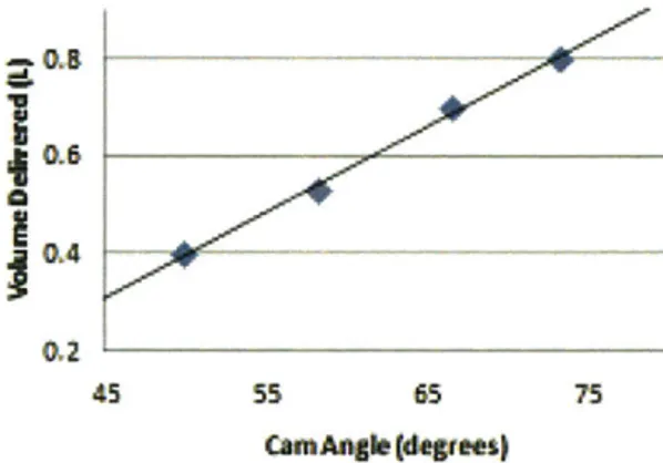
A set of experiments were performed on the second prototype to determine volume delivery and torque requirements. Flow rate was measured using a spirometer connected to the output of the BVM. Integrating with respect to time yields volume delivery of each compression stroke. Figure 5 shows a plot of the volume delivered with respect to cam angle. The plot shows that over the range of typical tidal ... .... -... ... .
volume settings, this relationship is linear. This relation allows for precise control of volume delivery.
0.6
1,4
45 55 65 75
CmAg(degee)
Figure 5: Volume delivered versus cam angle The force required to hold the cam at the peak of its stroke was measured using a force gauge. Using the known moment arm of the cam, these force measurements were then converted to torque values. It was found that the necessary holding torque is linearly related to volume delivered. The maximum cam torque required to compress the BVM was 2.64 N-m.
The torque output of the stepper motor is inversely related to the speed at which it is driven. Therefore, at lower driving speeds the device is able to deliver a higher tidal volume. At 5 bpm with i:e ratio of 1:2, the maximum volume delivery of the prototype is 0.9L. At 10, 15 and 20 bpm and with the same i:e ratio, the maximum volume delivery drops off to 0.8L, 0.7L, and 0.6 L respectively. While these results are not ideal, future iterations of the design will ensure that for all combinations of user inputs, the desired tidal volumes can be delivered. This should be achievable by further optimization of the shape of the cam and the constraints on the bag or increasing the gear ratio and motor size.
4.
Control Implementation Control designThe ventilator described in this paper can
operate in two modes: volume control (VC) Controller
I I . - "I 'll - 1111111111 11 ---- . ... : . ... ...
mode and assist control (AC) mode. The ventilator automatically operates in volume control mode but can at any time be overridden into AC mode by a breath attempt by the patient. To operate the ventilator, the medical provider selects the tidal volume (typically 6-8 mL/kg of ideal body weight), breaths per minute and i:e ratio. This provides a minimum assured minute ventilation (Ve). If at any time the patient spontaneously attempts a breath, a negative inspiratory pressure that exceeds 2cmH20 vacuum triggers the assist control mode and the ventilator immediately delivers the set tidal volume.
The advantage of the volume control mode is that the patient has an assured minute ventilation to ensure adequate gas exchange. The presence of the AC mode helps maintain synchrony between the patient's breath pattern and the breaths delivered by the ventilator. However, a disadvantage of the AC mode is that if the patient is tachypneic, respiratory alkalosis may develop or, for those with obstructive lung disease, air trapping may occur, raising intra-thoracic pressure with adverse hemodynamic
and gas exchange consequences. These issues are commonly handled with sedation. The combination of volume control and assist control is adequate for the management of the majority of clinical respiratory failure scenarios.
Parameters
The operator adjusts tidal volume, breaths per minute, and i:e ratio using three continuous analog knobs mounted to the outside of the ventilator. The prototype has a range of 0-900 mL tidal volume, 5-30 breaths per minute (bpm) and 1:2 to 1:4 i:e ratio. However, these values do not reflect the limits of the final design only the settings of the prototype. The ranges on the final design will be determined in consultation with respiration specialists to allow for the broadest range of safe settings.
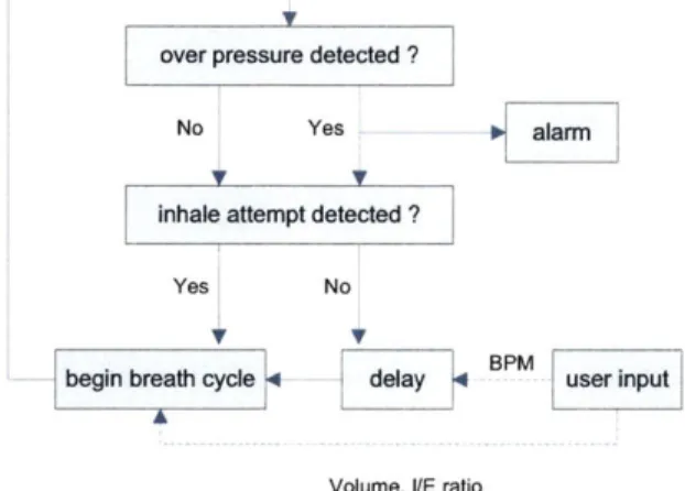
An off-the-shelf Arduino Nano microcontroller board was selected to control our device. The microcontroller runs a simple control loop to achieve user-prescribed performance. The control loop is triggered by the internal timer set by user inputs, with the inspiratory stroke initiated at the beginning of the loop. Once the prescribed tidal volume is reached, the actuator returns the cam back to its initial position and holds until the next breath. The loop then repeats to deliver intermittent breaths. If the loop is interrupted by a breath attempt (sensed through the pressure sensor), the ventilator immediately delivers a breath, interrupting the loop and resetting the timer. A diagram showing this loop is found in Figure 6.
over pressure detected ?
No Yes
V V
inhale attempt detected ?
Yes No:
V
begin breath cycle delay
+alarm
BMuser input
Volume, VE ratio
Figure 6: Ventilator control loop Motor
According to initial experiments, a maximum torque of 2.64 Nm was required for
maximum volume delivery of 0.9L. This value was used to size the motor chosen for the prototype. The stepper motor chosen is a bipolar configuration unit from Anaheim Automation, with part number 23Y002D. This is a square NEMA 23 frame size motor with double output shafts, which can provide 0.55 N-m of torque. With a gear ratio of 8:1, the cam can provide a maximum of 4.4 N-m of holding torque. The higher inductance coils (21.6 mH per phase) for this motor are acceptable due to the low speed range at which it will be operating.
Motor Driver
The motor driver comprises two H-Bridge circuits. These circuits direct current through the motor in opposite directions, depending on which set of switches on the circuits are energized. Speed of the motor is controlled by the pulse train generated by the Arduino. The power is supplied directly from the battery, so the only current limit is the current capability of the chip and battery.
We opted to use the Solarbotics@ motor driver, which is capable of supplying 2.92 amps of current to one circuit. While compressing the BVM, the motor was measured to draw 1.5 amps at a 50% duty cycle. This value is well below the peak current capabilities of the
components.
User Interface
The three user inputs (tidal volume, bpm and i:e ratio) are set via three potentiometer knobs. An LCD displays the current settings, as well as an error if high airway pressure is detected. There is a main power switch that disconnects the battery when the device is not in use.
Safety Features
To ensure that the patient is not injured, patient airway pressure is monitored with a pressure sensor connected to a sensor output on the BVM. The same pressure sensor used for assist control also triggers an alarm if system pressure rises too high, alerting the physician to attend to the patient. As a further safety measure to prevent over-inflation, future iterations of the device will include a mechanical pressure relief valve.
Power Delivery
An AC/DC converter can be used to power
the ventilator directly from a wall outlet or a vehicle inverter. When external power is unavailable, the ventilator can run off of any
battery capable of delivering 12-15 volts and 3.5 Amps. For the prototype, we used a 14.8 V, four-cell Li-Ion battery pack capable of 4.2 Amps, with a capacity of 2200 mA-hr.
5.
ConclusionsAn improved working prototype of the ventilator has been developed, relying on a double-shafted stepper motor and cams with integrated gear profiles to achieve BVM compression. The prototype has user-controlled tidal volume, breaths per minute and inspiratory to expiratory time ratio. It is also equipped with a pressure sensor allowing assist control and an alarm indicating over-pressurization of the system. The device has low power requirements, with a time-averaged power consumption of approximately 5W. It is portable, weighing 16 lbs (7.3 kg) and measuring 12 x 6.2 x 9 inches (305 x 157 x 229 mm), and features a handle and easy to use latches. An LCD screen on the user panel displays the user-prescribed settings. A preliminary DFMA model has been designed, and further development is planned. A scaled-down pediatric version will also be considered. Extensive testing of the ventilator's performance on a test lung is planned to ensure compliance with FDA standards.
6.
AcknowledgementsThe design and fabrication of this device was a term project in MIT Course 2.75: Precision Machine Design. We are grateful to Lynn Osborn and Dr. Tom Brady of The Center for Integration of Medicine and Innovative Technology www.cimit.org for providing support for course 2.75 and this project; and the VA Medical Center-West Roxbury. CIMIT support comes from DOD funds with FAR 52.277-11. Special thanks are due to Prof. Alex Slocum, Nevan Hanumara, Conor Walsh and Dave Custer for continuous guidance for the project. We are also thankful to Dr. Barbara Hughey for her help with instrumentation for our bench level experiments. The authors would also
like to thank SolidWorks Corporation for providing the solid model software used to create the models for this project.
7.
References[1] At-Khaled N, Enarson D, Bousquet J (2001) Chronic respiratory diseases in developing countries: the burden and strategies for prevention and management, Bulletin of the World Health Organization, 79 (10)
[2] Chan-Yeung M, Ait-Khaled N, White N, Ip MS, Tan WC (2004) The burden and impact of COPD in Asia & Africa. Int J Tuberc Lung Dis.
[3] Webster's New WorldTM Medical
Dictionary First, Second and Third Editions
(May, 2008) John Wiley & Sons, Inc. [4] McNeil, DG (2006) Hospitals short of
ventilators if bird flu hits, NYT, May 12 [5] Klein KR, Nagel NE (2007) Mass medical
evacuation: Hurricane Katrina and nursing experiences at the New Orleans airport. Disaster Manag Response. 2007
Apr-Jun;5(2):56-61
[6] deBoisblanc, B.P. (2005) Black Hawk, please come down: reflections on a
hospital's struggle to survive in the wake of
Hurricane Katrina. Am J Respir Crit Care
Med. Nov 15;172(10):1239-40
[7] http://www.news-medical.net/news/2009
1020/CDC-stockpiles-ventilators-for-use-during-public-health-emergency.aspx
[8] Kerechanin CW, Cytcgusm PN, Vincent JA, Smith DG, Wenstrand DS (2004)
Development of Field Portable Ventilator Systems for Domestic and Military Emergency Medical Response, John Hopkins Apl. Tech. Digest Vol 25, No. 3 [9] ASTM F920-93(1999)