Design and Process Optimization of a Hot Embossing
Machine for Microfluidics with High Aspect ratios
ARCHNE
fAA3SACHUSEThTS~
OFTECHNOLOGY
by
NOV
1
2 2013
Viren Sunil Kalsekar
JBRARIES
B.E. Honors, Mechanical Engineering, BITS Pilani, 2011
Submitted to the Department of Mechanical Engineering in partial fulfillment of
the requirements for the degree of
Masters of Engineering
at
MASSACHUSETTS INSTITUTE OF TECHNOLOGY
September 2013
© Massachusetts Institute of Technology, 2013. All rights reserved
Author:...
Department of Mechanical Engineering
August 9, 2013
Certified by:...
Dr. Brian Anthony
Thesis Advisor
Accepted by:
...
Dr. David E. Hardt
Ralph E. & Eloise F. Cross Professor of Mechanical Engineering,
Design and Process Optimization of a Hot Embossing
Machine for Microfluidics with High Aspect ratios
By
Viren Sunil Kalsekar
Submitted to the Department of Mechanical Engineering on August 9, 2013
In Partial Fulfillment of the Requirements for the Degree of
Master of Engineering in Manufacturing
Abstract
Microfluidics is a growing technology in the field of medical diagnostics. Daktari Diagnostics is a startup located in Cambridge, MA that seeks to introduce a lab-on-a-chip device for monitoring HIV in patients. This work investigates hot embossing as a prototyping process for Daktari's microfluidic device. A hot embossing system was designed and built for the purpose of prototyping a critical feature of their microfluidic network. The machine was designed for an embossing area of 6 square inches, and was found to have a maximum positional repeatability of 43 microns.
The purpose of this research was to find the capabilities of the system used for hot embossing and optimize the process for maximizing the performance. The system was validated for alignment, measurement procedure and the process control. The measuring procedure was analyzed to find the best possible metric which could serve as a response variable for the performance of the process. The 'Fill ratio' of height and width were chosen as metrics for the experimental design which had precision to tolerance ratios of 0.44 and 0.33 respectively. An analysis of the factors affecting the hot embossing process was carried out using experimental design and the optimal parameters were identified. The tool temperature, pressure and the holding time were the most significant in that order. The Cp for the process with respect to the height fill was found to be 4.71 and for the width fill ratio was found to be 1.97. Using the optimal parameters the process variation of six standard deviations was found to lie within the specification limits. Hot embossing was recommended as a possible method for rapid prototyping of the assay channel and the complete cartridge at Daktari Diagnostics. Thesis Supervisor: Dr. Brian Anthony
ACKNOWLEDGEMENTS
I want to thank my team mates and friends Nicholas Ragosta and Khanh Nguyen for their unbridled enthusiasm and support. It was great fun and a valuable experience working with them at Daktari Diagnostics.
Professor Brian Anthony, our advisor guided us through every phase of this project and his insightful advice helped us in channeling our ideas. I am grateful for the learning experience that he provided and he will always be an inspiration.
I would also like to thank Jennifer Craig for her help and advice on the technical writing throughout the semester.
I would especially like to thank Robert Etheredge, Aaron Oppenheimer, David Boccuti and Tony Sharma for the continual support and guidance throughout the project. I would also like to thank the whole Daktari team for the wonderful time we had at Daktari and I would take away a lot of knowledge and great experience.
Finally I would also like to thank my family and friends for being by my side and for their constant words of encouragement and support.
Table of Contents
1
Introduction ... 131.1 B ackground and R esearch M otivation ... 13
1.2 Problem Statem ent ... 14
1.3 Current Prototyping Processes ... 14
1.3.1 Photolith ography ... 14 1.3.2 M icrom achining ... 15 1.3.3 Injection M olding ... 15 1.4 U nm et N eeds ... 15 1.5 T h e H ot Em bossing Solution ... 16 1.6 R esearch O bjectives ... 17
2 B ackground and Product D escription ... 18
2.1 M icrofluidics ... 18
2.2 G eneral Card Features ... 20
2.3 T argeted Feature: T he A ssay Channel ... 21
2.4 G eneral Channel Considerations ... 21
3 R eview of Prototyping Processes ... 23
3.1 Photolithography ... 23
3.1.1 Process ... 23
3.1.2 Lim itations ... 24
3.2 M icrom achin ing ... 25
3.2.1 Process ... 25 3.2.2 Lim itations ... 25 3.3 Injection M olding ... 27 3.3.1 Process ... 27 3.3.2 Lim itations ... 28 4 H ot E m bossing Process ... 30 4.1 Selection of substrate ... 30
4.1.1 B asic Properties of T herm oplastics ... 31
4.2 T he H ot Em bossing Process ... 31
4.2.1 Initial H eating Stage ... 33
4.2.2 Em bossing Stage ... 33
4.2.4 D e-M olding Stage ... 34
4.3 C onsideration of Process Capabilities... 34
4.3.1 Sharp R adii... 34
4.3.2 U nfilled Extruded Features ... 35
4.3.3 Features Ending on Edges ... 36
4.3.4 C ontrol of T olerances and V ariability ... 36
4.3.5 A brupt and Variable Geom etries... 37
4.3.6 Surface Roughness... 38
5 M achine D esign A pproach ... 39
5.1 G eneral Effects of O perating Param eters ... 39
5.2 D esign R equirem ents ... 40
5.2.1 T ool and Substrate Fixture R equirem ents... 40
5.2.2 Force R equirem ent... 40
5.2.3 H eating Requirem ents ... 41
5.2.4 Cooling Requirem ents... 41
5.2.5 A lignm ent Requirem ents... 42
5.3 Com m on D esign Practices... 42
6 M achine D esign and Evaluation ... 44
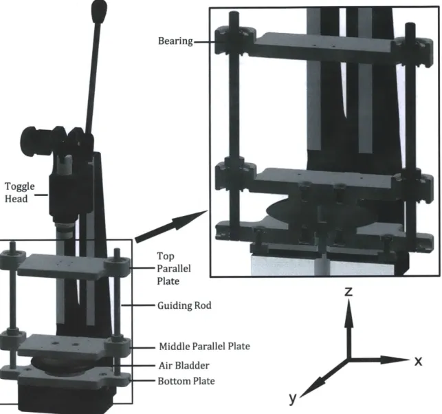
6.1 Full A ssem bly ... 44
6.1.1 O perational Procedure ... 45
6.2 Load B earing and T ilt Com pensation ... 45
6.3 T ool and Substrate Fixturing ... 47
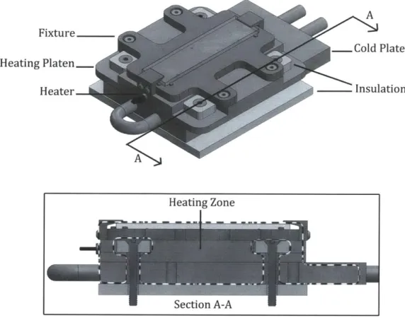
6.4 H eating and C ooling ... 48
6.5 Load Sensing ... 50
7 M ethodology: Process Control and Capability ... 52
7.1 Process and System V alidation ... 53
7.1.1 X & Y R epeatability ... 53
7.1.2 Parallelism ... 57
7.1.3 M easurem ent V alidation... 59
7.2 Process Evaluation & Performance Measurement... 60
7.2.1 Selection of Features on M icrofluidics Part... 60
7.2.2 Evaluation M etrics... 66
7.3 Process Param eters... 67
7.3.2 Force ... 68
7.3.3 H olding tim e... 69
7.3.4 D e-Em bossing T em perature ... 70
7.3.5 D e-E m bossing Force ... 70
7.3.6 E m bossing V elocity ... 71
7.3.7 M aterial of Part ... 72
7.3.8 T hickness of the Substrate... 73
7.3.9 M aterial of the T ool... 73
7.3.10 N oise Factors... 73
7.4 D ow n selection of Param eters ... 75
7.4.1 Cause and Effect M atrix ... 76
7.4.2 Pre D esign of Experim ents D ata ... 77
7.5 Design of Experiments (Fractional Factorial Model) ... 80
7.5.1 Controllable Factors... 81
7.5.2 U ncontrollable Factors (N oise factors) ... 82
7.5.3 R esponse V ariables:... 82
7.5.4 Fractional Factorial D esign ... 84
7.5.5 Experim ents ... 86
8 R esults ... 87
8.1 Analysis of Variance (ANOVA) and Significance of Effects ... 87
8.1.1 W idth Fill A nalysis... 87
8.1.2 H eight Fill ... 9 1 8.1.3 D e-Em bossing D efects ... 93
8.2 R esponse O p tim ization and A nalysis... 94
8.3 Confirmation Experiments to find Process Capability... 96
9 R ecom m endations ... 101
10 Conclusion and Future W ork ... 102
10.1 Conclusion ... 102
10.2 Future W ork... 103
10.2.1 M achine Im provem ents ... 103
10.2.2 Further Experim entation ... 105
A ppendix A ... 107
E ngineerin g D raw ing s:... 107
Sub-A ssem blies ... 108 Bill of M aterials ... 112 PA RTS ... 115 Data Sheets ... 124 A ppendix B ... 131 References ... 138
List of Figures
Figure 1: Critical parameters in microfluidics ... 19
Figure 2: Schematic of a channel with a capillary stop... 21
Figure 3: General channel dimensions ... 22
Figure 4 The positive mold (left) holds desired features and the negative mold (right) holds the opposite geometries of the features ... 24
Figure 5 Cross sectional depiction of burrs on the edge of a possible machined channel (left). An interferometer image of a machined feature showing tool marks and possible burrs...26
Figure 6 The standard process for milling the outside radius (left) and inside radius (right) of co rn e rs... 2 6 Figure 7: Injection Molding Process ... 28
Figure 8: The master tool (top) and substrate (bottom) are heated up (1), then pressed together (2) and finally released (3)... 32
Figure 9: General hot embossing temperature and force cycles. The process cycle begins from T = 0 to T = T 3 ... 3 2 Figure 10 The left image shows the dragging effect where the arrows indicate the direction of the tool and material movement. The right image shows air gaps which can reduce feature ra d iu s...3 5 Figure 11 Cavities in the mold can be unfilled during the embossing process if temperature, pressure, and holding time are not adequate... 35
Figure 12: Substrate edge distortion... 36
Figure 13 Schematic of a general cuvette feature... 37
Figure 14: Schematic of 3-way junction... 38
Figure 15: Depiction of misalignment... 42
Figure 16 Full assembly view... 44
Figure 17 Frame assembly and cross section views... 46
Figure 18 Visualization of misalignment air gaps. ... 47
Figure 19 Substrate fixture... 48
Figure 20 Substrate heating assembly and cross section... 49
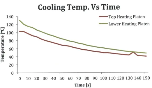
Figure 21 The cooling profile of the top and lower heating platens over a period of 2.5 mins.. 50
Figure 22 De-coupling of force sensor... 51
Figure 23 Fiducials used for x, y repeatability measurements ... 54
Figure 24 Distance between fiducials... 54
Figure 25: Error Band for the three Locations... 55
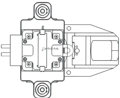
Figure 26: Central axis: ISO view ... 56
Figure 27: Central axis: top view... 57
Figure 28: Measurement Locations for Estimating Platen Parallelism... 58
Figure 29 Microscope Image of Channel Cross-Section ... 61
Figure 30: Microscope Image Close-up of Ridge ... 61
Figure 31: Channel Depth and Width...62
Figure 32 Ridge Height and Width...63
Figure 33: Channel Draft and Edge Radius... 64
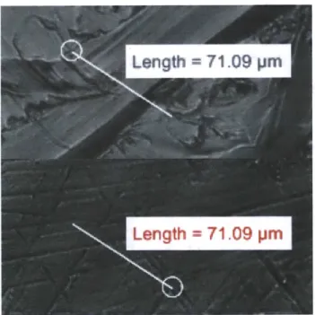
Figure 34: Scan of the Entire Length of an Embossed Channel ... 65
Figure 36: Interferometer Scan of Tool Marks on a Micro machined Tool... 66
Figure 37 Force Curve... 69
Figure 38 Embossing Temperature and Velocity Impact on Depth of Channel [24]...71
Figure 39 Co-existing Operating Ranges ... 80
Figure 40 Experim ental Design ... 81
Figure 41 Locations for M easuring D efects... 83
Figure 42 Exam ples of De-Em bossing Defects... 84
Figure 43 Pareto Chart for W idth Fill ... 88
Figure 44 Residual A nalysis of the W idth Fill... 89
Figure 45 M ain effect Plot...90
Figure 46 Interaction Effects ... 90
Figure 47 M ain Effects Plot for H eight Fill... 92
Figure 48 Interaction Effects for H eight Fill... 92
Figure 49 M ain effects for De-Em bossing Defects... 94
Figure 50 Response Optim ization ... 96
Figure 51Run Chart for Confirm ation Run ... 97
Figure 52 Process Capability A nalysis of the Ridge H eight ... 99
Figure 53 Process Capability Analysis of the W idth fill... 100
Figure 54 A ssem bly Draw ing... 107
Figure 55 Bottom Sub-A ssem bly... 108
Figure 56 Top Sub-A ssem bly... 109
Figure 57 Fram e Sub-Assem bly... 110
Figure 58 Substrate Plate Sub-Assem bly... 111
Figure 59 Bottom H eating Plate ... 115
Figure 60 Bottom Plate... 116
Figure 61 Sensor Block... 117
Figure 62 Top H eating Plate... 118
Figure 63 M iddle Plate... 119
Figure 64 Flange Shaft ... 120
Figure 65 Corner Insulation Block ... 121
Figure 66 Cold Plate... 122
Figure 67 Top Plate... 123
Fig ure 68 PD M S ... 124
Figure 69 PD M S ... 125
Figure 70 Epoxy Resin ... 126
Figure 71 Load Sensor ... 127
Figure 72 Tem perature Controller... 128
Figure 73 Bearings ... 129
Figure 74 Guiding Rods... 130
Figure 75 N orm al Plot for W idth Fill... 131
Figure 76 N orm al Plot for H eight Fill... 132
Figure 77 Residual Plot for H eight Fill... 132
Figure 78 Pareto Chart for H eight Fill... 133
Figure 79 N orm al Plot for De-Em bossing D efects... 134
Figure 80 Pareto Chart for D e-Em bossing defects ... 134
Figure 82 Interaction Effects for De-Embossing Defects... 135
Figure 83 Co-efficient for the regression model for De-embossing defects... 136
Figure 84 Co-efficient for the regression model for Height Fill... 136
List of Tables
Table 1: Measurement Data... 55
Table 2: Error Relation to Distance... 56
Table 3 Parallelism Measurements...59
Table 4 Summary of Gage RR Results [34] ... 60
Table 5 Cause and Effect Matrix...77
Table 6 Pre-Design of Experiments Data... 79
Table 7 Levels of Factors for the Fractional Factorial Design ... 81
Table 8 Aliasing Structure...85
Table 9 Fractional Factorial design parameters... 85
Table 10 Fractional Factorial Design Of Experiments ... 86
Table 11 ANOVA for W idth Fill...88
Table 12 ANOVA for Height Fill ... 91
Table 13 ANOVA for De-Embossing Defects ... 93
Table 14 Optimal Parameters for Confirmation Runs ... 96
Table 15 Confirmation runs ... 97
1 Introduction
This thesis explores using hot embossing as a prototyping process of microfluidic channels for Daktari Diagnostics. The capabilities of the process were investigated with specific emphasis placed on reproducing a key feature of their current product.
1.1 Background and Research Motivation
Daktari Diagnostics is a startup company that is currently specializing in affordable and accurate Human Immunodeficiency Virus (HIV) diagnostics. HIV replicates in the human body by invading helper T cells (specifically the CD4+T cells). As the virus spreads, the patient's CD4 cell count declines and their ability to fight infection diminishes. Thus, CD4 cell count (cells/microliter of blood) correlates to the severity of the infection. A measurement of CD4 cells cannot be used to diagnose a patient as HIV positive; however, it is an effective and essential measurement for determining if a patient is responding to medication. Measurement of the CD4+ T lymphocytes is a critical part in the staging of the HIV-infected patients, determining need for antiretroviral medications and monitoring the course of their infection[1].
In developed countries, the CD4 count (CD4 cells per microliter of blood) is performed every three to six months using a method known as flow cytometry. This requires expensive ($30,000 to $150,000) equipment and trained operators. In resource poor countries, these assets are only available in the largest national hospitals. For many patients afflicted by HIV, this means that they must send blood out from a local clinic and wait days or even months for the results to return from the central hospital laboratory. These economic and technical limitations have made these instruments difficult to sustain in resource poor environments[2], where there are more than 35 million HIV-infected people, 6 million of which require urgent anti-retroviral treatment. The need for a low cost CD4 measurement technique is widely recognized[3].
Daktari is attempting to create a CD4 cell count system that is simple to operate, low cost and portable. Their product includes a microfluidic cartridge with a circuit of channels for
reagents and blood to flow. The CD4 cells are preferentially captured in a basin known as the assay channel, and then counted using impedance measurements[2]. CD4+ cell size is on average 8.5 microns in diameter, with 0.2% being above 12 microns[4]. The microfluidic device contains channels as shallow as 50microns and as deep as 1mm.
1.2 Problem Statement
To arrive at a functional design, it is necessary that Daktari Diagnostics take advantage of manufacturing methods that are capable of producing parts with features in this 10s of microns range. For commercial production, Daktari will use an injection molding process. However, for prototyping this method may not be the most efficient. Daktari is interested in other manufacturing processes that are capable of accurately and reliably creating aspects of their microfluidic card for prototyping purposes. This thesis evaluates hot embossing as a prototyping process.
1.3 Current Prototyping Processes
Currently, Daktari uses several processes in conjunction for the development stage of the product. These are: Photolithography and Polydimethylsiloxane (PDMS) molding, micromachining, and injection molding. Each of these processes has limitations that prevent them from being ideal prototyping processes. The processes and limitations are discussed in more detail in 3; a brief description of each process is below.
1.3.1 Photolithography
Photolithography is a technique used to produce very precise (nanometer resolution) patterns on a substrate. The general principle of the process is that a photosensitive material is selectively exposed to a UV light source. This exposure cures portions of the resist in the desired pattern while the remaining material is etched away. The technique is commonly used to make integrated circuits, but has recently been used as a method for producing molds for
microfluidic applications. One major limitation of this process is the cost and complexity associated with making the mold. Another limitation, and Daktari's biggest concern, is that this process does not produce parts that are representative of production parts, meaning both the geometry of the parts produced and the material used differ from production specifications.
1.3.2 Micromachining
Micromachining directly into the substrate is another method that Daktari has used for prototyping microfluidic designs. Micromachining, either through micro milling, laser
machining or micro-electrical discharge machining (micro-EDM) is a subtractive
manufacturing process that affords great flexibility. This process is capable of producing complex micron scale features into almost any material desired. The major limitation here is the time required to produce a single part. It may take several hours to micro-machine one microfluidic design, and Daktari may need up to 50 parts made of a single design to fully evaluate it.
1.3.3 Injection Molding
Injection molding is the method currently used by Daktari for commercial production of their microfluidic card. Injection molding is a method in which a mold cavity is filled with a molten thermoplastic. It allows for highly complex parts to be rapidly produced. The major limitation of this process is the time and cost required to make a mold. A single mold cavity may take up to six months to design and manufacture. While this manufacturing process is desirable for volume production, it is not ideal as a prototyping process.
1.4 Unmet Needs
The processes described previously do not meet all of the requirements of an effective development tool for microfluidic devices. They are either prohibitively slow, prohibitively expensive, or produce parts that are not characteristic of parts produced with the production process. Therefore, there is a need for a more effective prototyping process.
The process must produce parts that are representative of production grade parts. This means that the behavior of flow through the channels in the prototyped parts must be similar to the flow that will occur in production parts. If this is not true, then the process cannot be realistically used as a development tool. The new development process must produce parts that have geometry representative of the final production parts. This includes tapers, surface roughness characteristics and material.
For the process to be an effective prototyping tool, it should take a relatively short amount of time to iterate on the design. This need translates to a requirement that has the entire process, from tooling to prototype production, be as short as possible.
1.5 The Hot Embossing Solution
Hot embossing is a viable solution for filling the prototyping gaps left by the previous processes[5]. It offers advantages in achievable feature replication[6], correct prototyping material, low process cycle time, and a variety of tooling options. Most features producible by injection molding and machining can be achieved by hot embossing, such as high aspect ratio features[7] and low surface roughness[8]. Mold tools for hot embossing can be produced through micromachining or lithography processes. The tools in hot embossing are used to transfer features over to substrate materials. The selection of substrate materials is very flexible and allows the correct material to be used for prototyping. The time in which it takes to make a single micro hot embossed part has been shown to be as low as 2min/part[9]. This bridges the gap between the fast process times of injection molding to the slow process time of micromachining. Hot embossing is able to bring prototype designs to production more quickly because the time required for tooling can be considerably less than that of injection molding where complicated features like ejection pins add to tooling time. Hot embossing also offers different materials for tooling that injection molding does not [8,10].
While there are many apparent benefits of using hot embossing, this technology is still an emerging manufacturing process that is not widely used commercially. The process exists primarily in academic and research settings and is still in the process of making a transition into commercial arenas. The true capabilities of the process will depend on the specific geometries of the parts being produced, and so this process must be evaluated for Daktari's particular needs.
1.6 Research Objectives
* To provide Daktari with a cost effective rapid prototyping technique with minimal lead time to enable manufacturing of the microfluidic backbone of the cartridge within tolerances.
e After selecting hot embossing as the process used for rapid prototyping, designing a
machine capable to produce the microfluidic parts within specifications and analyzing that design to find out the capabilities of the device.
* Validation of the complete process to characterize the process variation and the system repeatability. Analysis of the machine capabilities and the characterization of the boundaries of the operational capabilities of the device.
* Analysis of the various controllable and uncontrollable factors affecting the system and the down selection of the factors according to their impact on the features to be embossed. Analysis of a particular metric as a response for the experimental design which can be a measure of the performance of the system.
* Setting up of an experimental design to analyze the effects of the factors on the system. Analysis and optimization of the responses to find the optimal factors for the best performance of the process.
e Analyzing the process capabilities and characterizing the process window to attain
2 Background and Product Description
2.1 Microfluidics
The HIV diagnostic product developed at Daktari consists of a variety of parts but one of the most important and the critical part in the instrument is the microfluidic cartridge, which is manufactured using Poly methyl methacrylate (PMMA). The microfluidic cartridge is the component where the blood enters, mixes with different reagents in precise quantities and accurate measurements of the CD4 count of the blood are made. The important requirement for such a cartridge is having accurate quantities of the reagents and the blood flow at a precise rate through the channels. A microfluidic chip is suitable for this need.
Microfluidics has the potential to significantly change the way modern biology is performed. Using microfluidic devices we can work with smaller reagent volumes, shorter reaction times, and the possibility of parallel operation. They also hold the promise of integrating an entire laboratory onto a single chip (i.e. lab-on-a-chip)[11]. Apart from the traditional advantages of miniaturization, the greatest potential lies in the physics at the micro scale. By understanding and leveraging micro scale phenomena, microfluidics can be used to perform experiments which may not be possible on the macro scale which allows the introduction of new invention in functionality [12].
A microfluidic approach has been used for a wide range of applications which include analysis, diagnostics and synthesis [13]. Microfluidics is the analysis of accurate and precise flows through constrained routes or channels. Typically microfluidics is used to analyze fluids which flow, mix, separate and are processed otherwise. Some of the applications include passive fluid control using capillary forces, rotary drives applying centrifugal forces for the fluid transport on passive chips. Microfluidic chips can also be used to enhance rare cell capture and fractionation using biochemical interactions. Many of the microfluidic devices take advantage of the 3D structure of channels to increase the surface area available to be coated with the antibody [4].
There are a variety of ways in which the microfluidic chip can be manufactured which include soft lithography, micromachining and micro-injection molding. Some of the important parameters to be considered as shown in Figure 1 while producing the microfluidics part are:
1. Surface Finish: The surface finish plays an important role in the flow characteristics of the fluid and it depends on the process used for manufacturing.
2. Dimensional Tolerances on Features: The sides of the channel are important for the flow characteristics as well as the capture of any cells if relevant. The tolerance on these features like the width and length of the channels determines the flow characteristics. Also, the linearity of the features is an important along with the parallelism of the planes of the features.
3. Positional Tolerance: Parallelism and Perpendicularity with the outside boundary of the microfluidics may play an important role. Also, the positional tolerance of the features with respect to the outside boundary may be a crucial parameter.
Parallelism Corner Radius
Positional Dimensional
Tolerance Tolerance
Figure 1: Critical parameters in microfluidics
Most of the crucial parameters can be further listed down according to the application of the microfluidic chip, which is in this case the microfluidic cartridge used at Daktari. The
critical features and parameters which are important to the performance of the device are enlisted the following section. These features in addition to the parameters listed above will be the basis for evaluating hot embossing as an appropriate prototyping process for Daktari Diagnostics.
2.2 General Card Features
Several parts of Daktari's microfluidic network have unique aspects that make them difficult to prototype. These features are also parts of the microfluidic network that need to be thoroughly iterated upon to reach a functional design. Therefore, it is necessary to demonstrate that hot embossing is a suitable manufacturing method for these key features before it can be declared an effect prototyping tool.
Blood is first introduced to Daktari's product through a feature known as the fill port. This is an inlet that is designed to allow blood to be pulled into the microfluidic network of the card through capillary action. The inlet resides on an edge of the card. It will be a channel of uniform depth. The fill port may have uniform width, or it may have a design with a wide opening that tapers to the narrower width of the rest of the microfluidic network.
After blood has entered the card, it is important that the volume of blood to be analyzed be known. The metering channel is a portion of the microfluidic network that takes in a precise quantity of blood for transfer to the portion of the card that performs the analysis.
A capillary stop is a passive valve that prevents flow of fluid. By having an abrupt, large change in channel geometry, a pressure barrier is created that stops the flow of fluid [14]. Daktari uses capillary stops in their microfluidic network to direct the flow of blood. Figure 2 below shows an example of a capillary stop and how it operates. The fluid flows in the main channel past the capillary stop. Some fluid enters the stop, but its motion is halted when it reaches the portion of the channel that has a sudden change in depth and width.
Figure 2: Schematic of a channel with a capillary stop
2.3 Targeted Feature: The Assay Channel
The most critical portion of the microfluidic system is a portion of the card known as the assay channel. This is the region in which a crucial analysis of the blood is performed. It contains a large collection of tight tolerances and dimensions that are both unique to this area and common to different features on the card. Therefore, prototyping of this feature will be a good indicator of hot embossing's capability to prototype various parts of Daktari's card.
2.4 General Channel Considerations
The microfluidic channels in Daktari's product are in general defined by six basic geometric parameters. These are:
1. Depth. Channel depth varies widely on Daktari's microfluidic network and can be as shallow as 50microns or as deep as 1 mm.
2. Width. Channels of widths at large as 2mm in span exist on Daktari's card.
3. Draft Angle. This is a measurement of the verticality of the channel's walls. Perfectly vertical walls are desirable, but not possible because of the molding process currently being used.
4. Upper Radius. This is the radius at the upper edge of the channel. In general this radius is governed by radius of the tool used to make the mold.
5. Lower Radius. This is the radius at the bottom edge of the channel. The tool can be made with essentially 0 radius at this point, however there may be a radius left on the polymer part because of the manufacturing process.
6. Surface Roughness. This is a measure of wall smoothness. Lower surface roughness is desirable, for more predictable flow patterns and less trapping of cells. Surface
roughness requirements for this product can be as low as several tens of nanometers.
3 Review of Prototyping Processes
Many manufacturing processes can be used to produce parts with micro features. However, these micro features need to have a certain accuracy and fidelity. They need to satisfy the requirements of being biocompatible, corrosion-resistant and disposable etc. The manufacturing process needs to be viable with regards to the materials used and the feature size to be attained. Some of the potential manufacturing processes are discussed below based on the requirements listed above and manufacturing challenges. These processes are being currently used at Daktari for rapid prototyping the assay channel. Each of these processes has limitations that hot embossing will hopefully overcome.
3.1 Photolithography
Photolithography has been shown to be a cost effect and rapid way for producing micron scale features[15]. Additionally, photolithography in conjunction with Polydimethylsiloxane PDMS is commonly used as a means to prototype microfluidic channels[16].
3.1.1 Process
A positive mold containing the desired features is created using a photolithography process. The steps of the process are as follows and Figure 4 shows the differentiation of a positive and negative mold.
1. A photoresist resin is spin coated onto a silicon wafer
2. A mask is applied that covers some portions of the wafer and leaves other areas exposed
3. The wafer is exposed to UV light, this cures the resin not covered by the mask 4. The uncured resin is etched away leaving the completed silicon tool
Figure 4 The positive mold (left) holds desired features and the negative mold (right) holds the opposite geometries of the features
Once this silicon positive mold is completed, PDMS parts can be produced from it. Liquid PDMS is poured onto the positive mold along with a hardener. Once the PDMS cures, it is removed from the silicon positive mold and creates a negative.
3.1.2 Limitations
This process can create parts quickly. It may take a couple weeks to receive the silicon positive mold from a semiconductor foundry. However, once the tool is made, PDMS copies can be produced rapidly and at low cost. The greatest problem with this process is that it produces parts that do not have geometry or properties that are entirely representative of the final production process. Photolithography results in parts that have nearly perfectly vertical walls and can produce corners with almost non-existent radii[17]. Conversely, injection-molding (the production process) produces parts with tapered walls and corners with radii. Additionally, this process produces fluidic channels in PDMS, which is not the production
material. Material certainly has an effect on flow characteristics and because of this, results from testing PDMS parts may not be representative of how the design will perform with production material.
Another limitation of this process is that it is best suited for creating features with uniform height. Daktari's actual product is a microfluidic network with complex geometry with steps and ramping inclines. Therefore, this process is best for prototyping only portions of the design.
3.2 Micromachining
Micromachining can be used to produce parts with microfluidic applications because of the available working materials, machinable geometries, achievable feature sizes and surface
roughness[18]. 3.2.1 Process
Like traditional milling, a micro mill uses endmills with sizes as small as five microns that can cut into metals and softer materials. During the milling process, the endmill is moved relative to the work piece. This allows features to be cut directly into the thermoplastic substrate. In micromachining, the microfluidic channels are cut directly into the thermoplastic substrate. This process allows for complete control of the end part and is capable of producing many types of geometries.
3.2.2 Limitations
An advantage of micromachining is the flexibility afforded by the process. Once a micro mill is acquired, designs can be quickly iterated on. However, the benefit of not requiring custom tooling for each design is balanced by the relatively long cycle time of this process when compared to injection molding or producing PDMS parts from a silicon tool. Daktari anticipates needing 20-50 of any given prototype design for testing. This requirement makes the cycle time of micromachining each part undesirable.
A potential problem with micromachining is that tool marks left by the process may produce surface roughness characteristics that are undesirable. As mentioned previously, the cells of interest for Daktari are on the order of 1-10 microns. It is possible to achieve a surface roughness several orders of magnitude lower than this [18], however if the process is not carefully controlled then this characteristic might be problematic. Another artifact and problem with machining is the introduction of burrs which could have an impact on the performance or assembly of microfluidic devices. Burrs are introduced when material is not fully removed or becomes welded on the edges of a corner. Figure 5 depicts a cross sectional view of burrs and shows tool marks and potential burrs left by micro machining on aluminum.
Machining Burr
Figure 5 Cross sectional depiction of burrs on the edge of a possible machined channel (left). An interferometer image of a machined feature showing tool marks and possible burrs.
Micromachining also limits features such as sharp convex corners which are sometimes used in microfluidic devices to control fluid flow. An example of this use of sharp corners is to control capillary action where the sharp corners can be used to stop fluid flow. The radius of the endmill usually dictates the achievable radius on the interior of a corner, but usually not the exterior. Control and prediction of the corner milling resolution has also been seen as an issue in automated machining for mass production [19]. Figure 6 shows the common process for milling a corner.
--- g--e 6dr gs---sd
3.3 Injection Molding
Injection molding is a common process used to make parts containing micro-features. It offers the ability to use a wide variety of thermoplastic materials, many of which are biocompatible. 3.3.1 Process
Micro-injection molding is a process of transferring a thermoplastic material in the form of granules from a hopper into a heated barrel so that it becomes molten and soft. The material is then forced under pressure into a mold cavity where it is subjected to holding pressure for a specific time to compensate for material shrinkage as shown in Figure 7. The material solidifies as the mold temperature is decreased below the grass transition temperature of the polymer. After sufficient time, the material freezes into the mold shape and is ejected. This cycle continues to produce a number of parts. A typical cycle lasts between few seconds to few minutes [20]. The process has a set of advantages that make it commercially applicable. Advantages include the wide range of thermoplastics available and the scope for complete automation with short cycle times [21,22], cost effectiveness for mass-production process, especially for disposable products, very accurate replication and good dimension control, low maintenance cost of the capital equipment, when compared to the lithographic methods and applicability of the large amount of industrial information and technical know-how available for the traditional injection molding process. Also, because the working materials are injected into the cavities at a quasi-liquid state, the high mobility of the material makes making high aspect ratio, larger than 10, devices possible [23]. The process requires relatively inexpensive equipment and a metal mold to be produced. Additionally, the complexity of geometry possible is only limited by mold making capability. The dimensions of the injected parts fall into a region from 500 nm to several hundred micro meters.
Part o o o 0 o o o o o o 0 Mold Hopper Polymer Pellets
-K
Cylinder Machine PlatensFigure 7: Injection Molding Process
3.3.2 Limitations
However, because the working materials are processed under wide temperature range, from the room temperature to 10 to 20 degrees above the polymer melting temperature, the shrinkage of the material is large, and hence good uniformity in the walls with different thickness is hard to achieve[24].
Daktari will finally use the injection molding process for the manufacturing of the device on a mass-level. Once tooling is completed, their contract manufacturer is able to produce their backbone (cartridge) in a high volume and at relatively low cost per unit. If Injection molding is used as a prototyping tool, then parts produced are completely representative of what the parts will be like from a production run.
The major limitation of this process is the monetary and time investment required to make the mold. Lead times for precision micro molds can be in excess of 6 months, and changes to the mold design can take weeks to complete. While the fidelity achievable through injection molding is desirable, the time required to make tooling is too long for this process to
be an effective development tool. Daktari needs a prototyping tool which gives them a part which has the same material properties as the final part, which is made out of PMMA, be robust and function like the final product in a short period of time. This will enable reiterations of the design at a faster rate with a prototype, which is actually similar to how the product will work.
4 Hot Embossing Process
Hot embossing is a promising technique for manufacturing micro-fluidic devices due to its excellent feature transfer capabilities from master molds, with high aspect ratios and low roughness, onto polymers[7,25]. This meets the requirement for prototyping microfluidic devices that have varying feature sizes, surface roughness and complex geometries. It has also been shown that hot embossing has the capability for producing Poly methyl methacrylate
(PMMA) parts with microfluidic features and low cycle times[9,26].
The cost associated with creating the hot embossing master tool can be equal to or lower than injection molding in most cases [11]. On the other hand, the cost for the embossing equipment and materials are relatively low in comparison due to lesser heat and force requirements. Hot embossing requires much less force and heat in comparison to casting or injection molding. The working substrate is normally only heated to, or a little above, its glass transition temperature (Tg) and needs only a few MPa of pressure to transfer features from a master mold onto the substrate[27]. Hot embossing is a very flexible process that often only requires the change out of the master tool between prototype designs. The simplicity flexibility of the system drives engineering, material and energy costs down.
4.1 Selection of substrate
Daktari currently uses PMMA as the primary material for their diagnostic chip for many reasons. PMMA is used for the purpose of hot embossing and injection molding at Daktari because it is an economical alternative to polycarbonate, especially when extreme strength is not necessary. Also, PMMA does not contain the potentially harmful bisphenol-A subunits found in the polycarbonate. PMMA is often preferred as the polymer because of its material properties, easy handling and processing and low cost. The glass transition temperature (Tg) of atactic PMMA is 105 C (221 F). The forming temperature starts at the glass transition temperature and goes up from that point. PMMA is a strong and lightweight material with a density of 1.17-1.20 g/cm3, which is less than half of that of glass and has an ignition
low-molecular weight compounds including formaldehyde. PMMA is the least hydrophobic of all the common plastic materials. Moreover, its optical clarity is also a significant benefit for the testing purposes. PMMA will be the primary material used in this work since it is commonly used in hot embossing and is the material used for Daktari's diagnostic chip.
4.1.1 Basic Properties of Thermoplastics
A thermoplastic is a thermo-softening polymer that becomes pliable with an increase in the temperature and returns back to the original solid state with cooling. Most of the thermoplastics have a high molecular weight and its massive molecular chains have high intermolecular forces binding them together. These forces help in the binding of the material once the temperature cools down and hence the polymer can set back into its solid state. Above its glass transition temperature Tg and below its melting point Tm the physical properties of a thermoplastic change drastically without an associated phase change. Within this range, the thermoplastic is a rubbery mass due to alternating rigid crystalline and elastic amorphous regions approximating random coils. This makes hot embossing of these thermoplastics possible without working in a broad temperature range like in case of injection molding. Brittleness might be a deterring factor for the hot embossing process and this can be reduced with the addition of plasticizers, which interfere with the crystallization to effectively lower the Tg. Modification of the polymer through co-polymerization or with the addition of non-reactive side chains to monomers before polymerization can also reduce the Tg.
4.2 The Hot Embossing Process
Hot embossing is the process in which a substrate is impressed with features from a master tool. The master tool holds the negative of the desired features so that the positive of the features may be transferred. It is also very common to heat up the master mold and usually results in better feature transfers and lower cycle times[25]. Figure 8 depicts the process overview with the master tool and substrate.
*
0 0
*
0
Figure 8: The master tool (top) and substrate (bottom) are heated up (1), then pressed together (2) and finally released (3)
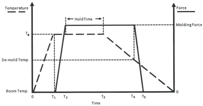
Figure 9 shows the force and temperature cycle of the hot embossing process. The process cycle starts when the substrate begins heating up to or past its glass transition temperature, Tg, from To to Ti. At T1, the master tool is pressed into the substrate and held for a period of time at a constant molding force. The holding time lasts until T2, at which time the substrate is set to
cool. At T3 the substrate temperature reaches below its Tg to a desired de-molding temperature
and the molding force is released, ending the process cycle.
Ternperature De-mold Temp. Room Temp. +4-HoldTime -+ I ---~1~ I I I
I!
N: IN:
I'
I
I
0 Ti T2 T3N%
T4 TS Force MoldingForce 0 TimeFigure 9: General hot embossing temperature and force cycles. The process cycle begins from T = 0 to T = T3
I MOMEMMONd
4.2.1 Initial Heating Stage
Referring to Figure 9, the heating stage occurs between To to Ti. During the initial heating stage, the substrate is heated up to or a little past its Tg. It is also very common to heat the tool up at this time to the same temperature of the substrate or a bit cooler[28]. This initial heating prepares the substrate to be malleable and less viscous for the embossing stage. The higher the substrate temperature is, the less force is required. Also, a higher replication accuracy is correlated with better material flow[29]. Uniform heat distribution is preferable because it can dictate the quality of the part and complexity of process control and analysis. Control and repeatability of the temperature during this stage is desired for quality and process control purposes.
4.2.2 Embossing Stage
The embossing stage spans from T1, the time in which the master tool and substrate come into contact, to T4, when the tool and substrate start to separate. The embossing stage
initiates from T, to T2, during which time the tool and substrate come into contact and force
begins to be applied and ramped up to a desired load. Once a desired force is reached, it is kept constant from T2 to T4. Constant force as well as constant position can be kept during this time, depending on the types of features required. For example, a part may have to be made to a certain thickness. This would only be achieved under constant position holding and not force. The holding time occurs between T2 to T3 and defines the amount of time that the substrate is
placed under constant force and heat, or position and heat. 4.2.3 Cooling Stage
Cooling happens after T3 and is the stage that brings the substrate below its Tg.
De-molding temperature plays a large role in the final shape of the embossed part and is usually set well below the substrates Tg. Releasing the molding force at too high of a temperature may cause the substrate material to flow and fill in the features that were created[29]. Cooling rates also has an effect on thermal stresses, which would affect part quality[30,31]. For the purposes of this work, the cooling rate does not have to be rapid and can be kept such that the best quality parts are produced. A long cooling time (-10mins) would be acceptable.
4.2.4 De-Molding Stage
De-molding begins at T4, at which point the substrate has been cooled below its Tg to a
desired de-molding temperature. Force application is released at this point and the tool and substrate are pulled apart until there is no longer contact, at T5. De-molding can require a considerable amount of force depending on the size of the part, features, and amount of friction between the tool and substrate[5]. Materials such as mold release may be used in order to facilitate the de-molding process, but could potentially yield undesirable part quality, especially for a feature that requires tight tolerances. The de-molding process has been shown to contribute greatly to the quality of the part, especially when friction and substrate shrinkage are considered. Parts have been seen to have poor quality because of high friction and shrinkage[32]. Control of how the tool and substrate separate can also have an effect on the part quality. It has been recommended that the tool and substrate be separated initially at a single location or edge, then "peeled" away from one another[5].
4.3 Consideration of Process Capabilities
To consider hot embossing as a viable rapid prototyping process for Daktari, it must have capabilities in replicating a wide range of features. This section will provide an overview of some of the features that may be challenging for hot embossing to accurately and precisely produce. These features include many of the channel parameters introduced in chapter 2, as well as features that are specific to the assay channel.
4.3.1 Sharp Radii
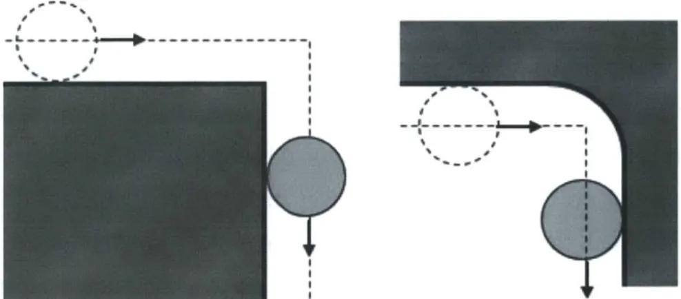
Many features such as the assay channel require a sharp radius on raised edges. During the hot embossing process, the substrate exhibits a "dragging" behavior where the sidewalls, near the tip of the tool feature, "drags" the substrate as pressure is applied between the tool and substrate. This dragging process can wear the tip of the tool out while creating air gaps. Figure 10 shows a cross section of a channel and how air gaps can increase the radius on the raised edge. These air gaps can be reduced by increasing forming temperature so that the
substrate can more easily flow and fill the gaps[33]. Increasing pressure and embossing hold time can also help reduce these gaps.
Figure 10 The left image shows the dragging effect where the arrows indicate the direction of the tool and material movement. The right image shows air gaps which can reduce feature radius.
4.3.2 Unfilled Extruded Features
The filling of high aspect ratio cavities can be difficult and can depend on the temperature, pressure, and hold time. The effects that cause incomplete filling in corners may also contribute to this incomplete filling of extruded features. Figure 11 shows an unfilled cavity during the embossing process. The substrate is pushed into the cavity, but if the hold time, pressure and temperature are not adequate, then the substrate may not be able to flow and fill the cavity.
Figure 11 Cavities in the mold can be unfilled during the embossing process if temperature, pressure, and holding time are not adequate.
4.3.3 Features Ending on Edges
It may be necessary to have features that reside directly on the edge of an embossed card, such as a fill port. Producing features that reside on the edge of an embossed part may be difficult for the hot embossing process. Figure 12 displays a possible fill port design, which can be referenced back in section 2.2. The image on the left is the ideal part produced through hot embossing. The image on the right displays a part that is more representative of the process. The reality of the process is that edge distortions are often present on the embossed part. This is because the heating and pressing on the substrate causes material flow that is unconstrained at the boundaries of the substrate. This may be problematic when producing features that must reside on the edge of a part. Boundary bowing may also occur if the tool is smaller or of the same size as the substrate. Material that is not under constant pressure from the tool will deform with random warping during cooling.
Ideal edge condition Actual edge condition Figure 12: Substrate edge distortion
4.3.4 Control of Tolerances and Variability
It will be necessary to demonstrate the capability of hot embossing to produce features with tightly controlled dimensional tolerances. Referring to the assay channel in section 2.3, it is important that this feature maintains very low variability in the dimensions of the channel card to card and that the dimensions are precise as possible. The assay channel is a straight rectangular channel with a defined ridge around its perimeter. Figure 13 below shows what the assay channel may look like. The two holes represent inlet and outlets for a fluid.
Sectdon - A Figure 13 Schematic of a general cuvette feature
For hot embossing to be an effective method of producing this channel it is necessary that the variability of the process be well understood. This feature will also test the capability of hot embossing to fully transfer the mold onto the substrate. It will be critical to know what percentage of the mold geometry is transferred into the substrate. For example, if the mold has a feature with a cross section that is 10 microns deep and 10 microns wide, it will be important to know how closely the corresponding feature on the embossed part matches these dimensions.
4.3.5 Abrupt and Variable Geometries
Another common feature for this microfluidic network are areas where multiple channels come together at a junction. These junctions may bring channels together that have different depths and different widths. The hot embossing process must be capable of producing features of variable depth, either with a gradual incline at the bottom of the channel or with a step. The process must also be capable of producing features with variable width. Figure 14 below displays one possible design for a junction of multiple channels. Notice the change in channel width from the left to the right. This sudden change in width may be a necessary aspect of Daktari's product. It will be necessary to investigate the capability of the hot embossing process for producing channels with sharp corners, like those seen at the junction. Another variable dimensional control would be in the depth of channels. The channels should be a constant depth along the length and width so that their functionality can be more predictable.
Figure 14: Schematic of 3-way junction
4.3.6 Surface Roughness
The cuvette feature requires not only tight tolerances, but also a low surface roughness. This feature is a wide and very shallow basin (roughly 50 microns in depth). Therefore, tight dimensional tolerance of the channel depth and width are critical. Additionally, surface roughness of the bottom surface is of paramount importance in the assay channel. The CD4 cell counting is occurring in this channel; therefore surface roughness must be maintained at a level that does not cause unwanted trapping of cells. The assay channel will also challenge the capability of hot embossing to produce large and smooth surface area features.
5
Machine Design Approach
This chapter will outline the design requirements needed for an embossing machine that is capable of making Daktari's assay channel. The general effects of different operating parameters will be described so that a basic idea of how different components and their operating ranges can work together to make parts. Design requirements will then be discussed. Current design practices that are in-line with this study will then be highlighted to help with the design.
5.1 General Effects of Operating Parameters
Hot embossing feature replication is largely dependent upon three factors; embossing temperature, pressure, and embossing time. The combination of values of the three settings effects not only the cycle time of the embossing process, but the achievable quality of the embossed substrate. For example, low embossing temperatures would require high pressures in order to achieve the same results as high embossing temperature and low pressures [1]. The lower embossing temperature would decrease the heating and cooling time resulting in a possible decreased cycle time. This assumes that the embossing time is equal for both settings.
The tradeoff between these different settings would be in equipment size, cost, process cycle time, and achievable feature resolution. It is important for this design to be flexible with embossing temperature and pressure in order to accommodate future tool designs. Embossing and cycle time is not as important because it has been decided that low volume (20-50) production is required for prototyping.
5.2 Design Requirements
The following design requirements help guide machine design so that it may be able to hot emboss Daktari's microfluidic feature.
5.2.1 Tool and Substrate Fixture Requirements
It was decided that the embossing system should be able to accommodate the master tool and substrate material with surface sizes ranging from 25mm x 90mm to 65mm x 100mm.
All sub features of the microfluidic device are able to fit on a 25mm x 90mm area, which
provides flexibility in designing and testing of such features. The microfluidic device is able to fit into the 65mm x 100mm area, allowing for prototyping of the entire device. The substrate normally has the same surface size as the master tool, so the fixture holding the substrate should be positioned and orientated in the same manner as the tool. Repeatable placement of the substrate is not critical as long as the tool is able to emboss all features onto the substrate without deformation. The substrate can be reworked after embossing so that deformed edges can be taken off, so long as features do not reside on them. The fixture should also be able to hold down the substrate during the de-embossing phase so that the tool and part can be separated.
5.2.2 Force Requirement
Daktari has chosen PMMA to be the working material for the microfluidic device. Forming pressures as low as 1MPa can be used for high temperatures and long embossing times, but on average, 2MPa is used for embossing micro features on PMMA, and 4MPa being a rare case [2]. 2MPa is used as the standard requirement, hence with the entire microfluidic chip measuring 63mm x 100mm, a working force of 12.6OkN would be required. It should be noted that the working force could be lower than 12.6OkN since increasing embossing temperature or time could achieve the same results as working with this load. Also, pressure is the least sensitive variable in the embossing process because it normally only needs to be above a certain threshold [3]. The machine should also be able to meet de-molding forces, which could be high for large parts. It was determined that the machine did not have to initially
meet 12.6OkN of force since the largest embossing area that would be tested initially would be
22.50cm2.
For a 2MPa application pressure, a working force of 4.5kN would have to be met.
5.2.3 Heating Requirements
Commercially available PMMA has a Tg of between 85 to 1650C, thus the embossing temperature must be able to reach above this temperature. The specified maximum operating temperature was chosen to be 2000C in order to accommodate any future changes in plastic
selection for prototyping. Popular plastics such as polycarbonate, polystyrene, and Zeonex have, on average, Tgs below 2000C. It should be noted that hot embossing can tolerate
embossing temperature tolerances of +/- 30C, so the accuracy of temperature control is defined by this tolerance [2]. Heating rate is not as important because the entire process is not aimed to be rapid and is allowed to take up to half an hour. The substrate only needs to be brought to a desired temperature and kept there. Uniform heating should be considered in order to increase process control and part quality.
5.2.4 Cooling Requirements
It has been shown that the de-embossing temperature has an effect on not only the cycle time, but also on the quality of the embossed substrate [3]. The cycle time, in the case of prototyping 20-50 microfluidic parts, is not as important as the quality of the part itself. A cycle time of up to 30 minutes is acceptable in this case. Although cooling rate has an effect on part quality, the system does not require precision control of this parameter as long as it is consistent with every embossing run and fits within the 30min process window. As noted earlier, cooling over a longer period of time typically provides for better parts that suffer less from thermal stresses.
5.2.5 Alignment Requirements
Alignment of the heating platens is important because part planar uniformity is dependent upon this. Figure 15 shows how platen alignment can affect a part.
Embossed Part
Figure 15: Depiction of misalignment
Alignment requirements, defined primarily by Daktari's microfluidic chip, concern planar x and y travel, angular rotation and vertical parallelism. Daktari has expressed interest in possibly embossing features on both the top and bottom surfaces of a substrate. This double embossing would require features from one side to line up with features on the opposite side. Unfortunately, there is currently no specified high precision x, y and angular alignment requirements because of a lack of understanding on how top and bottom features will perform together under misalignment. However, planar alignment and vertical parallelism should be designed to as high tolerance as possible while considering costs and time.
5.3 Common Design Practices
Simple thermocouples and liquid cooling systems have been shown to be an effective way to measure and facilitate in temperature control[9]. Effective cooling and heating systems help to drastically reduce the process cycle time. The cost associated with this system is associated with the desired cooling rate, accuracy, and thermal mass to be cooled. Temperature control has been shown to be an important parameter in reducing embossed part defects[5].