Publisher’s version / Version de l'éditeur:
Vous avez des questions? Nous pouvons vous aider. Pour communiquer directement avec un auteur, consultez la
première page de la revue dans laquelle son article a été publié afin de trouver ses coordonnées. Si vous n’arrivez pas à les repérer, communiquez avec nous à [email protected].
Questions? Contact the NRC Publications Archive team at
[email protected]. If you wish to email the authors directly, please see the first page of the publication for their contact information.
https://publications-cnrc.canada.ca/fra/droits
L’accès à ce site Web et l’utilisation de son contenu sont assujettis aux conditions présentées dans le site LISEZ CES CONDITIONS ATTENTIVEMENT AVANT D’UTILISER CE SITE WEB.
Internal Report (National Research Council of Canada. Institute for Research in Construction), 1998-06-01
READ THESE TERMS AND CONDITIONS CAREFULLY BEFORE USING THIS WEBSITE. https://nrc-publications.canada.ca/eng/copyright
NRC Publications Archive Record / Notice des Archives des publications du CNRC :
https://nrc-publications.canada.ca/eng/view/object/?id=6c6afbc4-1a7c-475b-b364-4758b5d1090d https://publications-cnrc.canada.ca/fra/voir/objet/?id=6c6afbc4-1a7c-475b-b364-4758b5d1090d
NRC Publications Archive
Archives des publications du CNRC
For the publisher’s version, please access the DOI link below./ Pour consulter la version de l’éditeur, utilisez le lien DOI ci-dessous.
https://doi.org/10.4224/20331622
Access and use of this website and the material on it are subject to the Terms and Conditions set forth at
Fire Resistance of FRP Reinforced Concrete Slabs
Kodur, V. K. R.; Baingo, D.
S F R ' TW1. R 4 2 7
nlnc,"
COP..
2 no.. 7 4 8 d u n eNational Research Conseil national
I*I
Council Canada de recherches CanadaFire Resistance
of FRP
Reinforced Concrete Slabs
by
V.K.R. Kodur and D. BaingoInternal Report No. 758 Date of Issue: June 1998
.
C I S T I / I C T S T NRC/CNRCI R C S m r
R m c s i v e d nn r 0 7 - O R - 9 R I n t e r n a l , r a p o r t . .
FIRE RESISTANCE OF FRP REINFORCED CONCRETE SLABS
by
V . K . R . Kodur and Darek Baingo
TABLE OF CONTENTS List of Tables
...
ii List of Figures...
ii ... Nomenclature...
III Executive Summary ... iv...
. 1 Introduction 1 1.
1 General...
1 1.2 Types of FRP Materials...
1 1.3 Applications of FRP...
2I
. 4 Advantages and Disadvantages of FRP...
3. . 1.5 Objective and Scope
...
42 . Fire Resistance of FRP-Reinforced Concrete
...
82.1 General
...
82.2 Literature Survey
...
82.2.1 Properties of FRP at Elevated Temperatures
...
82.2.1.1 Mechanical Properties
...
92.2.1.2 Deformation Properties
...
I0 2.2.1.3 Thermal Properties...
1 1...
2.2.1.4 Other Properties 1 1 2.2.2 Fire Tests on Structural Elements...
122.3 Summary
...
14 3 . Numerical Studies...
22 3.1 General...
22...
3.2 Numerical Model 22 3.2.1 Analysis Procedure...
23 3.2.2 Material Properties...
23 3.2.3 Computer Program...
23 3.2.4 Program Verification...
24 3.3 Numerical Studies...
. . 25-
3.3.1 Slab Charactenstrcs...
~5
3.3.2 Effect of Reinforcement...
253.3.3 Effect of Aggregate Type
...
263.3.4 Effect of Concrete Cover Thickness
...
26...
3.3.5 Effect of Slab Thickness 27 3.4 Summary...
274
.
Conclusions and Recommendations...
364.1 Conclusions
...
364.2 Recommendations
...
365 . Acknowledgements
...
366 . References
...
36LlST OF TABLES
Table 1.1 Properties of various FRP composites and other materials [81
...
5Table 1.2 Thermal properties of various FRPs and other materials at room temperature 11-61
...
6Table 2.1 Elastic constants of the CFRP laminate at elevated temperatures 1121
...
15Table 2.2 Average coefficients of transverse thermal expansion for various GFRP composite materials at elevated temperatures 1151
...
15Table 3.1 Details of slabs used for the validation of the numerical model ... 28
Table 3.2 Details of slabs used in the parametric studies
...
28LlST
OF
FIGURES Figure1
.1
Longitudinal tensile loading of a continuous parallel fibre lamina [9]...
7Figure 2.1 Variation in measured elastic stiffness with temperature for CFRP 1121 ... 16
Figure 2.2 Relationship between elastic constants and temperature for CFRP [12]
...
17Figure 2.3 Tensile stress-strain curves for CFRP at various temperatures [I 11
...
17Figure 2.4 Compressive stress-strain curves at various temperatures [l 11
...
18Figure 2.5 Variation of strength with temperature for different materials
...
19...
Figure 2.6 Creep of an off-axis specimen under tensile loading of 76 MPa [Ill 20 Figure 2.7 Change in length vs . temperature for three GFRP composites [I51... 20
Figure 2.8 Properties of the NEFMAC reinforced slabs as tested 1191
...
21Figure 3.1 Variation of strength with temperature for FRP and steel
...
29Figure 3.2 Arrangement of elementary layers in the model for a concrete slab
...
30Figure 3.3 Flowchart showing numerical procedure used in the computer program for calculation of slab fire resistance
...
30...
Figure 3.4 Comparison of predicted temperatures from the model with test data 31 Figure 3.5 Effect of reinforcement type on fire resistance of reinforced concrete slabs...
32Figure 3.6 Effect of aggregate type on the fire resistance of reinforced concrete slabs
...
33Figure 3.7 Effect of concrete cover thickness on the fire resistance of reinforced concrete slabs
...
34Figure 3.8 Effect of slab thickness on the fire resistance of reinforced concrete slabs
...
35NOMENCLATURE
tensile modulus of elasticity in the longitudinal direction (MPa); tensile modulus of elasticity in the transverse direction (MPa); shear modulus (MPa);
shear strength (MPa); Temperature in "C
specific heat (Jlm3."C),
compressive strength in the longitudinal direction (MPa); compressive strength in the transverse direction (MPa); tensile strength in the longitudinal direction (MPa); tensile strength in the transverse direction (MPa);
specified 28-day concrete strength (MPa);
coefficient of heat transfer at the fire exposed surface (J/m2-m-"C) thermal conductivity (J/s.m.OC)
time in hours
coordinate along slab cross section Greek Letters:
A = increment;
y = coefficient of convective heat transfer from concrete to air;
E = emissivity between fire and concrete surface; v = Poisson's ratio;
p = density;
cr = Stefan Boltzmann constant (5.67~10-~ J/s.m2."K4 x 3600 slhr), Subscripts: f = m = M
=
n = 0 = max = 1 = 2=
of the fire;at a point in the m-th elementary layer; at a point in the M-th elementary layer; concrete type;
initial; maximum
longitudinal direction, along fibres (Table 1 .I) transverse direction, across fibres (Table 1 .I) Superscripts:
FIRE RESISTANCE OF FRP REINFORCED CONCRETE SLABS
by
V. K. R. Kodur and Darek Baingo
EXECUTIVE SUMMARY
World-wide interest in the use of fibre-reinforced plastic (FRP) reinforcement in concrete structures, as an alternative to traditional steel reinforcement, has increased significantly in recent years. FRP reinforcement offers many advantages over steel, such as high strength and durability (non-corrosive). While FRP reinforcement is mainly used in bridges, there is enormous potential for its use in multi-storey buildings, parking garages and industrial structures.
Before FRP can be used in structural members in buildings, the ability of these materials to meet stringent fire-resistance requirements, prescribed in building codes, must be established. At present, there is very little information available on the performance of FRP-reinforced structural members in fires.
To assess and develop the needed information on the fire resistance of FRP- reinforced concrete structural members, a feasibility study was undertaken with the main emphasis on fire resistance of FRP-reinforced concrete slabs. The literature review revealed that there is very little information on the material properties of FRP at elevated temperatures. Also, not much data is available on the behaviour of structural elements reinforced with FRP under fire conditions.
A numerical model in the form of a computer program was applied to the analysis of FRP-reinforced concrete slabs, by making relevant assumptions, and a series of parametric studies was carried out. From these limited parametric studies, it was found that:
The FRP-reinforced concrete slabs have a lower fire resistance in comparison to the slabs reinforced with steel.
The factors that influence the fire resistance of FRP-reinforced concrete slabs are the concrete cover thickness and the type of aggregate in the concrete.
A higher fire resistance for FRP-reinforced concrete slabs can be obtained through higher concrete a v e r thickness to reinforcement, and through the use of carbonate aggregate in the concrete mix.
There is an urgent need for establishing the fire performance of FRP to facilitate its use in building applications.
FIRE RESISTANCE OF FRP REINFORCED CONCRETE SLABS
V. K. R. Kodur and Darek Baingo
1 INTRODUCTION
1.1 General
Fibre-reinforced Plastic (FRP) composite materials are created by the synthetic assembly of two or more distinct materials on a macroscopic scale. The basic
constituents of such a material, fibres and a resin and sometimes other fillers, are combined in order that the composite material exploits the best of their individual qualities. The FRP materials exhibit overall properties, such as high strength-to-weight ratio, corrosion resistance and fatigue strength, that are superior to those of the
individual constituents and to most traditional metallic materials. They are often classified as Advanced Composite Materials (ACM).
Advanced composites, including FRPs, have been widely employed in the aeronautical, transportation and chemical industries over the past twenty-five years. However, their use in civil and structural engineering is recent and their full potential is yet to be realized. The present high cost of production and the lack of knowledge about FRP by the civil and structural engineering profession are two major obstacles limiting their wide application.
In recent years, there has been increasing interest in the use of FRP as
reinforcement in concrete structures and in other forms, such as sheeting. While its use is, at present, mainly confined to bridge structures, there is an enormous potential for the application of FRPs in multi-storey buildings, parking structures and industrial structures.
1.2 Types of FRP Materials
FRP composites consist of two key elements, namely the fibres (glass, carbon or aramid) and a thermosetting polymer matrix such as epoxy, vinyl ester, phenolic or polyester resin. The commonly-used types of FRP composite materials can be divided into three basic groups: Glass Fibre-Reinforced Plastic (GFRP), Carbon Fibre-
Reinforced Plastic (CFRP) and Aramid Fibre-Reinforced Plastic (AFRP) composites. The fibres are embedded in the matrix which acts as the binder material for the composite and transmits the applied loads to the fibres.
Glass fibres are the most widely used since they can be produced at relatively low cost and their specific characteristics are well known. They offer good mechanical behaviour combined with high tensile strength, however, they have a low modulus of elasticity, as well as high abrasion, alkaline and moisture sensitivity. Some of the lightest fibres are obtained with carbon. Although more expensive than glass, they produce stiffer uni-directional composites, can maintain their strength up to 2000°C and have a
high resistance to chemical attack. They do however, have low toughness and impact resistance. Aramid fibres, such as Kevlar, have good thermal stability, high strength and stiffness and excellent impact resistance.
The matrix, in general, has poor mechanical characteristics. The behaviour of the matrix is dependent on time, the rate and frequency of load application and the ambient temperature. When load is maintained over a long period of time, creep or visco-elastic behaviour will occur.
The overall properties of an FRP are functions of the relative proportion of fibres and matrix and their physical and mechanical properties. The relative proportion, fibre- resin ratio, is usually expressed as a volume fraction of the composite. The strength and stiffness of an FRP composite is provided by the fibres and, hence, the maximum
strength of the composite material occurs in the direction of the fibres.
The fibres have properties which are significantly superior to those of both the matrix and the composite material. By reinforcing a low modulus matrix with h~gh strength, high modulus fibres, a high strength, high modulus composite material is produced, as illustrated in Figure 1 .I. The figure also shows a typical stress-strain relationship for a mild steel in relation to the FRP curve. The most important differences between the steel and FRP curves are the lower modulus of elasticity of the FRP and the linear behaviour until the occurrence of sudden and brittle failure. These differences result in composite materials having larger deformations at lower stress levels and low ductility.
A summary of typical room-temperature mechanical properties for various types of FRP, in comparison
tb
other commonly used construction materials is presented in Table 1.1. The table shows that, unlike steel and other metals, the material properties of FRP are different for the two principal directions, along the fibres (Example E,) and transverse (Example E,) to the fibres. This is because the properties, in the longitudinal direction, are governed by the fibres while the matrix governs the properties in the transverse direction. The shear strength of the composites is also much lower than that of steel.Table 1.2 contains thermal properties, namely the coefficients of thermal
exoansion and thermal conductivity, for various materials at room temperature. As with the mechanical properties, the thermal properties are also dependent on direction. As can be seen, the longitudinal coefficient of thermal expansion (CTE) is lower than that of steel, however, the transverse CTE is much higher than that of steel. The information presented in Table 1.2 is taken from References 1-6.
1.3 Applications of FRP
FRP composites have been used extensively in aeronautical and other industries, but uncertainties about their durability and long-term properties, such as fatigue
performance and creep, have limited their use in civil engineering applications. Recently, however, structural FRP composites have made the transition from the aerospace and automotive markets to the construction industry. Applications include FRP reinforcement for concrete, external FRP sheets and panels for the strengthening
and retrofitting of existing structures, large plate enclosures for steel bridges, and even structural elements made entirely of FRP.
FRP products are available in various configurations, such as reinforcing bars, pre-stressing tendons, two- and three-dimensional grids, and loose fibres known as micro-fibres. Designers are particularly interested in FRP reinforcement for concrete structures because they offer a corrosion-resistant alternative to steel reinforcement.
Carbon micro-fibres can be used to increase the tensile strength of concrete and reduce the amount of steel reinforcement needed. Appl~cations include reinforcement of concrete railroad ties and external cladding panels for buildings. The mass of composi:e cladding panels is often 113 to 112 that of conventional panels.
FRP products, like the ones described above, are also used for rehabilitation and strengthening of existing structures. The demand for economical and effective
retrofitting methods is stimulated by the environmental degradation of the now aging infrastructure, in addition to a steady increase in the allowable weight of highway vehicles over the last thirty years.
Many older structures do not meet the requirements of modern seismic design codes and must be retrofitted. The FRP products offer potential economical alternatives for accomplishing these tasks. For instance, bridges can be strengthened with internal or external FRP post-tensioning tendons. As an alternative to steel plate bonding,
CFRPepoxy sheets can be used for rehabilitation, by bonding single or multiple layers of such laminae to either concrete or steel structures. Likewise, FRP fabrics and braided fibre tapes can be used for 'tvrapping" beams and columns of buildings as well as parking structures in seismic regions thereby greatly increasing their ductility and strength.
1.4 Advantages and Disadvantages of FRP
The combination of chemical resistance of the resin, along with excellent tensile strength of the fibres, creates a number of advantages for FRP composites. For
example, the strength-to-weight ratio of FRP is between 10 and 15 times that of steel. This means that a smaller proportion of a member's load-bearing capacity [7] is used to support its own dead load; thereby allowing for a larger live load and, hence, a more efficient use of available capacity [7]. Also, the lower weight of structural elements reinforced with FRP might make handling and installation generally much easier, further reducing construction costs. The fatigue strength of CFRP and AFRP is also about
3 times that of steel [8] and their resistance to salt water is excellent.
The resistance of FRP to corrosion makes it particularly attractive for use in civil engineering applications, especially in reinforced concrete structures. The initial high cost of FRP can be effectively offset by the potential overall economy resulting from reduced maintenance costs and better durability. Further, variability of durability, stiffness, strength, shape and colour can be achieved by altering factors such as the method of manufacturing and the types of resin, fillers and fibres used.
There are, however, some drawbacks to using FRP materials compared to traditional steel. The stress-strain relationship of FRP is linear and results in a sudden and brittle failure and, thus, FRP composites have low ductility. Most FRP composites are anisotropic. Their mechanical properties are highly dependent on the orientation of the embedded fibres and, hence, on the direction of stresses to which they are
subjected. Moreover, the deformations in FRPs are greater than in steel at the same stress level. Also, at present, there is uncertainty about the durability of FRP
reinforcement and little is known about alkali-cement reaction with FRP reinforcement.
There are currently no design guides or manuals dealing with the design of FRP- reinforced structures. Also, the almost total absence of information on the high
temperature properties of FRP materials, as well as on the fire performance of structural elements reinforced with FRP, further hinders their application in buildings.
1.5 Objective and
Scope
The main objective of this study is to present the state-of-the-art on the behaviour of FRP-reinforced concrete structural elements at elevated temperatures. Particular emphasis is placed on the fire performance of FRP-reinforced concrete slabs. The objectives of this study are:
To conduct a literature search and review the studies on the material properties of FRP composites at elevated temperatures, as well as experimental and numerical studies on the behaviour of FRP-reinforced concrete elements exposed to fire. To apply a computer model to analyze the behaviour of FRP-reinforced concrete slabs exposed to fire.
To carry out parametric studies to determine the influence of various parameters on the fire behaviour of FRP-reinforced concrete slabs.
The literature review on the material properties and structural element behaviour is reported in Section 2. Details of numerical studies are reported in Section 3 and the conclusions and recommendations for future work are contained in Section 4.
Table 1.1. Properties of various FRP composites and other materials [8]
Table 1.2. Thermal Properties of various FRPs and other materials at room temperature [I-61
STRAIN
(
Figure 1 .I. Longitudinal tensile loading of a continuous parallel fibre lamina [9]
2. FIRE RESISTANCE OF FRP-REINFORCED CONCRETE
2.1 General
One of the major safety requirements in building design is the provision of appropriate fire resistance for structural members. The National Building Code of Canada
[lo]
specifies fire resistance requirements and provides fire resistance design equations for steel reinforced and steel prestressed concrete structural members b y prescribing minimum member dimensions and minimum concrete cover thickness to the reinforcement. In the case of steel reinforcement, the concrete cover thicknessrequirements for fire resistance serve, to a certain extent, to fulfill the requirements for corrosion control
For FRP-reinforced concrete structural members, no special concrete cover thickness provision is required for corrosion control. However, because FRP-reinforced concrete members are often thinner, in comparison to steel reinforced structural
members, the provision of minimum concrete cover to FRP reinforcement is necessary to satisfy fire resistance requirements and may be very different from the requirements for steel reinforcement to achieve fire safe construction.
Similar to other structural members, the fire resistance of FRP-reinforced structural members can be determined either by testing or calculation. In order to determine the fire resistance of FRP-reinforced concrete structural members through calculation, the material properties of FRP as well as concrete at elevated temperatures is required.
The results of the literature review are presented in the following sections. This includes the material properties of FRP, as well as the results of fire tests on FRP- reinforced concrete members.
2.2 Literature Survey
To assess the performance of FRP-reinforced concrete structural members, the material properties of both FRP reinforcement and concrete, as a function of
temperature, are required.
At present, there is very little information on the material properties of FRP at elevated temperatures. Data on fire tests of FRP-reinforced concrete structural
members is equally scarce. This can be attributed to the fact that the application of FRP- reinforced concrete in civil engineering structures was, until now, mainly limited to
infrastructure projects, where fire resistance is generally not a consideration.
2.2.f Properties o f FRP at Elevated Temperatures
To evaluate the fire resistance performance of concrete structures, the properties of the constituent materials at elevated temperatures are required. In the case of FRP- reinforced concrete structures, the material properties of both FRP and concrete are necessary. These properties, that determine the performance of structures exposed to fire, are mechanical, deformation and thermal.
2.2.1. I Mechanical Properties
Generally, the strength of materials decreases with increased temperature. When FRP-reinforced concrete members are subjected to heat at relatively slow rates, there is uniform heating through the surface of the material. This leads to a gradual temperature rise in the FRP reinforcement. As a result, structural failure often occurs prior to the melting or sublimation temperature of the FRP reinforcement. Failure is caused by the degradation of mechanical properties of the reinforcement with increased temperature.
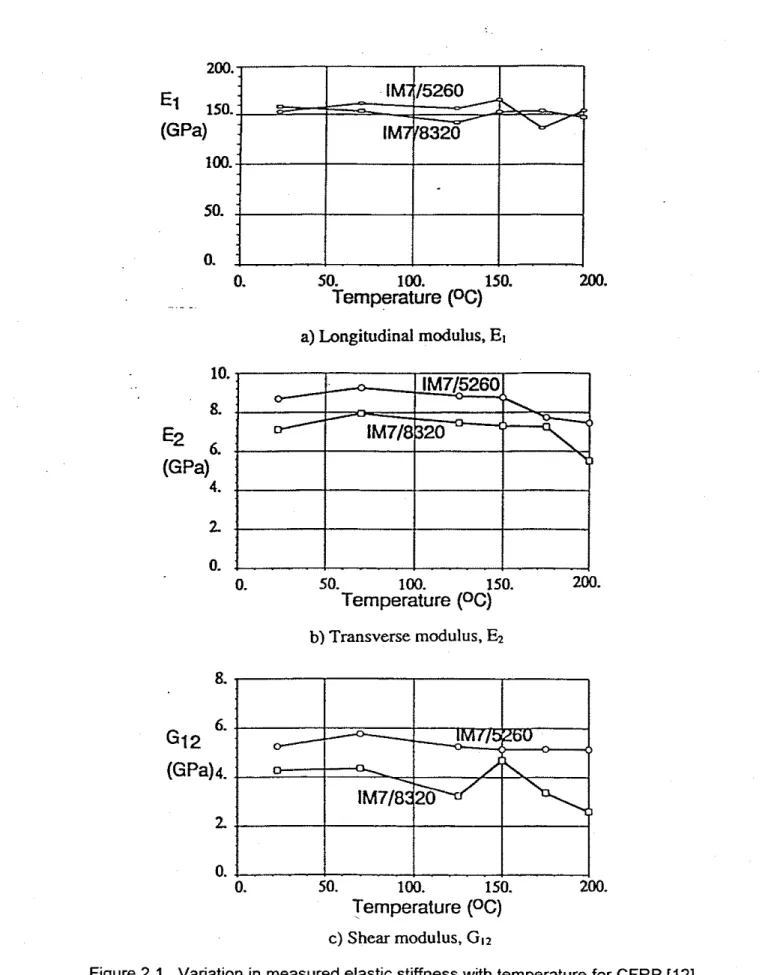
Elastic Modulus -Variation of elastic moduli of a typical CFRP with temperature is illustrated by the three charts in Fig. 2.1, as reported by Gates [ I l l . Figures 2.1 (a) to (c) show the longitudinal, transverse and shear moduli, respectively, of two different uni- directional carbon-fibre composites (lM715260 and lM7/8320), tested in the 23OC to 200°C temperature range. IM7 are commercially available carbon fibres, while 5260 (bismaleimide) and 8320 (thermoplastic) represent the two types of commercial resins used for the matrix. The glass transition temperature, T,, for both of these matrices was given by the manufacturers as 220%. The temperature, T,, reflects the thermoset matrix curing reaction and is, for most purposes, considered to be the upper temperature for the use of the material.
As can be seen in Figures 2.1 (b) and (c), respectively, the transverse (E,) and shear moduli (GI,) decrease as temperature increases. The longitudinal modulus of elasticity (El), shown in Fig. 2.1 (a), on the other hand, appears to be relatively insensitive to temperatures in the range considered. This is because the fibres have good temperature resistance and govern mechanical behaviour of the composite in the longitudinal direction. In the transverse direction, the composite behaviour is controlled by the matrix, which is sensitive to increasing temperature. The temperature range considered, however, lies below the glass transition temperature and the mechanical properties of the matrix are mostly affected beyond the glass transition temperature.
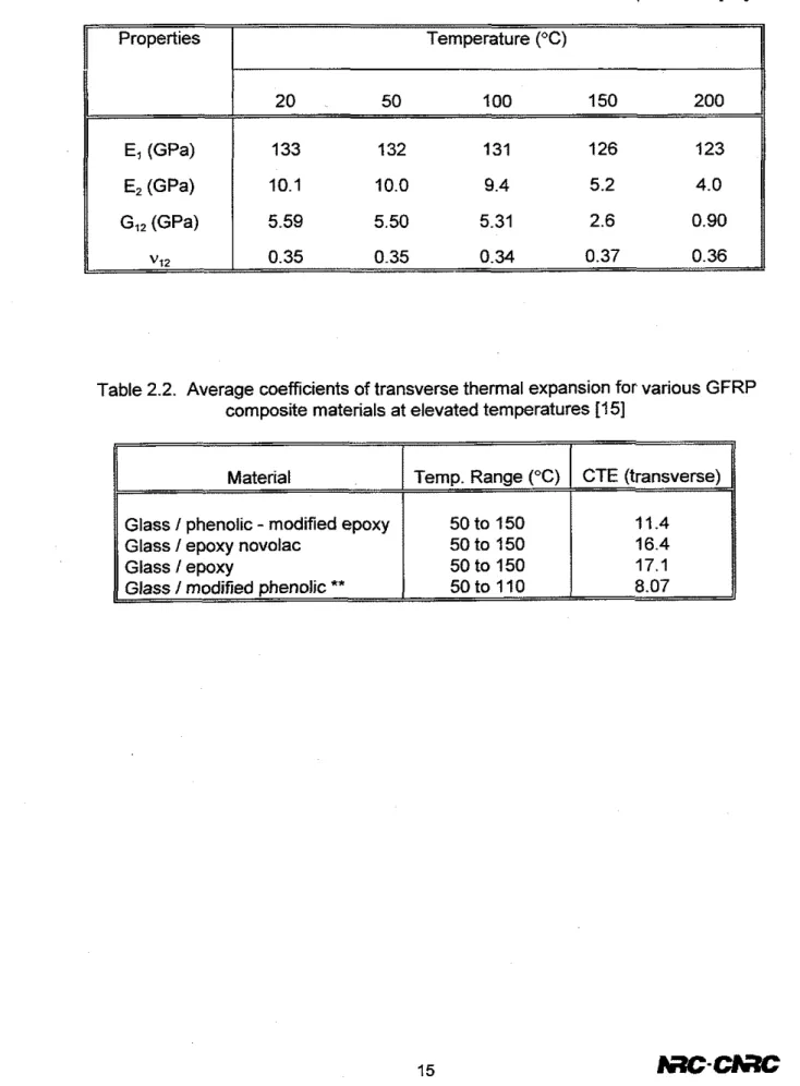
Uematsu et al. [I21 reported similar results for a CFRP (ASWPEEK) composite material. The CFRP composite laminate consisted of carbon fibres, known commercially as AS4, embedded in a thermoplastic polymer matrix poly(ether ether ketone) (PEEK). The values of the longitudinal and transverse elastic moduli, E, and E,, respectively and the shear modulus
G,,,
are given in Table 2.1. In addition, the results are showngraphically in Fig. 2.2. The elastic constants are normalized with respect to those at room temperature (20°C) and are plotted as a function of temperature, from 20°C to 200°C.
Also, for this composite, El is nearly independent of temperature whereas
E,
andG,,
decrease markedly in the region of the glass transition temperature for PEEK, T,, of 140°C. The decrease in the parameters begins to occur at about 100°C. By 20OoC, El is reduced by only lo%, whereas E, and G,,, decrease by 60% and 82%, respectively. This was attributed to the fact that the elastic constants of the fibre are independent of temperature while the matrix is softened as the temperature approaches T, [12]. The same authors also investigated the effect of temperature on Poisson's ratio, v,,(Table 2.1) and concluded that, in the temperature range considered, v,, is independent of temperature.
Strength
-
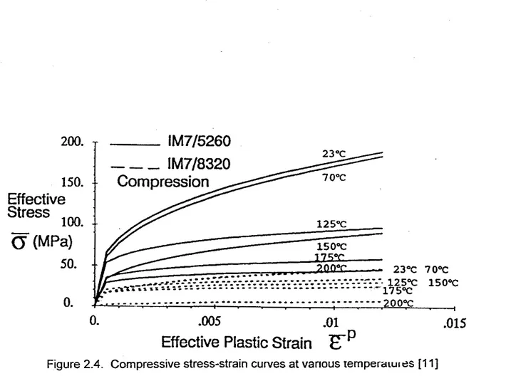
Gates [ I I ] studied the stress-strain relationships, both tensile and compressive, for the two CFRP composites (lM715260, lM718320). These stress-strain relationships are shown in Figures 2.3 and 2.4, respectively. From the figures, it can be seen that the tensile and compressive strength of lM715260 composite reduces to approximately 50% at about 125OC and to about 75% at a temperature of 200°C. The strain level, for a given stress, is also higher with the increase in temperature.Based on the above information, a curve for the variation of strength with temperature for FRP is plotted in Figure 2.5 and compared to other traditional
construction materials. In the figure, the ratio of strength at elevated temperature to that at room temperature is plotted. As with steel, concrete and wood, the strength of FRP decreases with increasing temperature. While the data for concrete, steel and wood is well documented [6], the curve representing the strength degradation of FRP is based on the limited information reported in the literature and presented in this report. As can be seen in the figure, up to 100°C, there is very little strength loss for FRP. Then the strength degradation is faster, resulting in a 75% strength loss at 250%.
2.2.1.2 Deformation Properties
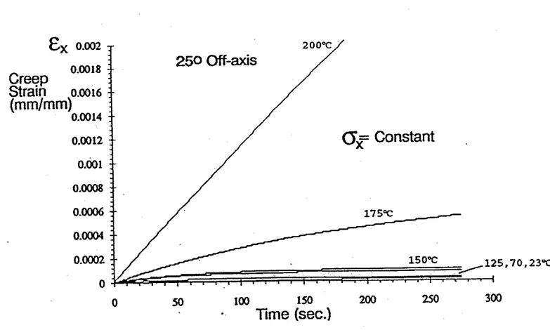
Creep -The effect of creep, at elevated temperatures, on the behaviour of FRP- reinforced concrete structures is significant. Figure 2.6 shows the effect of temperature on the creep strain of an off-axis CFRP composite, at a constant stress of 76 MPa, as reported by Gates [ I 11. It can be seen that the increase in creep strain is particularly large above 150°C. For instance, after 150 seconds, the creep strain at 200°C is about 18 times the creep strain at 150°C.
Thermal Expans~on -Another deformation property that plays a significant role in the fire behaviour of structural members is thermal expansion. The coemcient of thermal expansion (CTE) represents the change in unit length of a material due to unit
temperature rise or drop. Its value is used for calculating dimenstonal changes as well as thermal stresses caused by temperature variation. As in the case of mechanical properties, the CTEs for uni-directional laminates are different in longitudinal and transverse direct~ons. At room temperature, the CTEs of composites are generally higher than the CTEs of steel [I-61. Depending on the fibre type, orientation and volume fraction, the CTE of FRPs can vary over a wide range of values.
The transverse thermal expansion of FRP reinforcements for concrete is different from that of concrete [13, 141. The tensile stresses in concrete members, reinforced with FRP, that can result from this incompatibility in thermal expansion, may lead to cracking of the concrete. This is of concern due to the possibility of FRP reinforcement debonding from the concrete or causing the spalling of concrete and thereby a loss of strength and serviceability of FRP-reinforced concrete structural elements [14]. This problem could also severely limit the structural safety of FRP-reinforced structures in fires.
Test results on the thermal expansion of various types of GFRP composites were reported by Silverman [15]. Several different resins were considered while the same glass fibre fabric was used in all specimens. The thermal expansion of the GFRPs was measured in the matrixdominated direction (transverse to the fibres) in the 25OC to 400°C temperature range. The change in length, as a function of temperature, for some of the composites is shown in Figure 2.7. It was concluded that the thermal expansion in the matrix-dominated direction increased dramatically above the 150°C to 200% range. This range coincides closely with the glass transition temperature, which was established by that author to be 185"C, for the GFRP composites considered. Table 2.2 contains the average CTEs, in the transverse direction, for four GFRP composites tested by
Silverman [15]. The values are valid in the 50°C to 150% temperature range for most materials.
2.2.1.3 Thermal Prooerties
Information on the thermal parameters of FRP composite materials at elevated temperatures is scarce. This is most likely due to the fact that such information is proprietary to the composite materials manufacturers. Most of the available literature, therefore, deals only with general trends for the thermal properties.
Thermal
-
- Conduct~v~ty -Thermal conduct~v~ty, k, represents the capac~ty of amaterlal to conduct heat For comDoslte mater~als ~ ~ d IS a funct~on of the fibre t v ~ e .
..
. fibreorientation, fibre volume fraction and laminate configuration. At room temperature, polymers, in general, have low thermal conductivity. This makes them useful as
insulation materials. However. Mallick [9] stated that, in some circumstances, they may also act as a heat sink since they are not able to dissipate heat efficiently. This leads to a temperature rise in the material which in turn affects its performance.
With the exception of carbon fibres, FRPs have a low thermal conductivity. As with the mechanical and deformation properties of uni-directional composite materials, the longitudinal thermal conductivity, k , is controlled by the fibres and the transverse conductivity, k,, is controlled by the matrix.
2.2.1.4 Other Properties
Charring
-
During a fire, the matrix is the most affected component of an FRP composite material because of its low melting temperature and can hence be considered the weak link. Its relatively poor performance is due to the high content of carbon,hydrogen and nitrogen, which are combustible materials [16]. Although burning of FRP reinforcement in concrete has not been reported in the literature, ~ a l t o n [I71 reported charring of discontinuous Kevlar fibres when used as reinforcement in concrete panels
Smoke Toxicity
-
Neale and Labossiere [I61 reported that, during a fire, polymers generally produce large amounts of very dense, sooty, black smoke and that some components of that smoke, such as carbon monoxide, may be toxic to humans. While charring of the matrix in FRP reinforcement may not be a serious problem in FRP- reinforced concrete members exposed to fire, due to the presence of the concrete cover,it may be necessary to test FRP products for evolution of smoke and toxins, in addition to fire resistance.
Other Properties
-
Numerous resin additives are available for enhancing the resistance of matrices and FRPs to flames, heat, smoke generation, moisture, oxidation, chemicals and shrinkage [8]. The additives are introduced into the resin during themanufacturing process of the FRPs. For example, phosphorous flame retardants function by developing a protective char which separates the unburned polymer from the flame and heat source. Hydrate-based flame retardants, such as alumina tryhydrate, undergo endothermic reactions and release water upon heating, thereby cooling and quenching the combustion reactions [8]. Such additives can slow down the strength degradation of FRPs subjected to elevated temperatures. Information on the mechanical performance of FRPs treated with resin additives, however, is not available. Burn and Martin [I81
reported that the addition of fire retardants to GFRP composites increases the evolution of smoke under fire exposure. Furthermore, most additives increase the moisture content of FRPs and this, in turn, has a negative effect on their mechanical properties and thermal stability [16].
2.2.2 Fire
Tests
on Structural ElementsOnly a few test programs have been undertaken to determine the fire resistance of FRP-reinforced structural elements; one was carried out by the NEFCOM Corporation in Japan on concrete slabs reinforced with glass fibre and carbon fibre grids [19]. These grids are a newly developed composite material commercially available under the trade name NEFMAC.
Ten loaded slabs, measuring 3500 mm long and 500 mm wide, and having a thickness of 120 mm, were tested by exposing them to fire, on one side, for a maximum of two hours. Figure 2.8 shows a typical layout of slabs used in the experimental studies. One of the slabs was reinforced with a traditional steel mesh to measure its performance relative to the slabs reinforced with the FRP grids.
The test parameters considered included the load intensity, the type of fibre (glass, carbon or both) and resin used for the FRP grids, equivalent bar size of the grids, concrete cover thickness, the presence of a joint and the presence of fire protective covering on the exposed
sulfate
of the slab. The protective covering consisted of a 25 mm thick rock wool board. The data measured included the deflections and temperatures at various cross-sectional locations of the slab including that in the NEFMAC grid.Based on these fire tests, the following results were reported:
1. For NEFMAC grid reinforced slabs with glass fibres (GF) and no external insulation, the deflections increased rapidly when the bottom surface temperature of the
NEFMAC reached 600°C. This was caused by the stiffness deterioration of the glass fibres at high temperatures.
2. No particular differences were observed in the behaviour of slabs reinforced with grids containing different resins (vinyl ester or unsaturated polyester). This
conclusion was based on the comparison of the deflections for two specimens, up to a temperature of 600°C on the bottom surface of the NEFMAC.
3. For a constant cover depth, the temperature rise in NEFMAC was almost the same regardless of the type of fibre or resin used. The temperature rise of the steel mesh in the steel reinforced concrete slab was slower than that of the NEFMAC reinforced slabs at the same concrete cover depth. This is because the thermal conductivity of steel is about 100 times that of the NEFMAC and the heat capacity of steel is about twice that of NEFMAC [19].
4. Slabs with joints failed before the bottom surface temperature of the NEFMAC reached 500°C because the strength degradation of the intersections of the grid due to the deterioration of the resin.
5. Slabs protected with a rock fibre insulation protective cover showed higher fire resistance. In fact, the maximum temperature in the NEFMAC at the end of the test was 170°C compared to 600°C in the slabs without insulation. In addition, the
limiting deflection limit of 72.9 mm before120 min was never reached; the actual deflection at 120 minutes was about 25 mm.
6. The larger the applied load, the shorter the fire resistance time of a specimen because of the larger resulting deflections.
7. There were almost no recognized differences in deflections of slabs reinforced with NEFMAC and of the slabs reinforced with steel mesh [19].
The deflections of the NEFMAC-reinforced concrete slabs were equivalent to the deflection in the steel reinforced-concrete slab until the NEFMAC temperature reached 60OoC, regardless of the types of fibres or resin used in the NEFMAC grids. Based on the test data, the authors projected that full-scale NEFMAC reinforced slabs of 3.0 m x 6.0 m dimensions, under a live load of 2.9 kNlm2 and no internal joint, would provide a one hour fire resistance when the concrete cover depth is 15 mm. If a joint exists, a 30 mm cover is required to ensure a one hour fire resistance rating. These values are for slabs without insulation.
The most interesting information from these experiments is that temperatures in NEFMAC in excess of 600°C were reported. The information available in the literature on the material properties of FRPs, shows that, for most composite materials, the majority of strength is lost by about 200 to 250°C, which seems contradictory to the above findings. However, it is possible that chemical additives, which delay strength degradation at high temperatures, might have been used to treat the NEFMAC matrix for fire resistance. Information on any of the additives is not reported.
Walton et al. 1171 conducted fire tests on concrete panels reinforced with
randomly distributed discontinuous Kevlar fibres. Kevlar fibres are organic and made of an aramid polymer known as polyamide. The fibres, which were 51 mm long and had a
diameter of about 11.7 pm, had a tensile strength of 2,900 MPa, a Young's Modulus of 130 GPa and a break elongation of 2.6%. In the fire tests, one side of the panel was heated to a maximum temperature of 920°C while the other side was left exposed to ambient air. It was not indicated whether the panels were loaded. The test was continued for 1 hour.
The authors reported that, during the first 15 minutes, water was driven off as steam which caused delamination in patches and some surface cracking. Examination of the panel after the test showed that most of the fibres had completely charred but those nearest the unexposed side (which reached a temperature of 400°C) had not charred and still had sufficient strength to allow handling of the panel without
disintegration. Monitoring of the air near the panel, during the tests, revealed no toxic gases. High temperature tests on individual fibres revealed that most of the strength was retained up to 200°C.
2.3 Summary
From the literature survey, it was found that there is very little information
available on the material properties of fibre-reinforced plastics, at elevated temperatures, and on fire tests of structural elements reinforced with FRPs. This is due to the fact that, until recently, the use of FRPs in structural engineering was mainly in infrastructure projects, where fire resistance was not a major issue.
The material properties of FRPs at elevated temperatures are controlled by the fibres in the longitudinal direction and by the matrix in the transverse direction. The limited data indicates that the general impact of elevated temperatures on the behaviour of FRP composites is a severe degradation of material properties. These include a reduction of strength and stiffness with increasing temperature, as well as an increase in deformability, thermal expansion and creep. In general, it was found that the effect of temperature on the material properties is not significant up to 100°C. Above this temperature, however, degradation can be quite rapid as the glass transition
temperature of the matrix is reached. The glass transition temperature, which is often considered the upper critical temperature, varies with the type of resin used and was found to be as low as 100°C for some resins and as high as 220°C for others. Based on the limited studies, it appears that as much as 75% of the FRP strength and stiffness is lost by the time the temperature reaches 250°C. There is also not much information on evolution of smoke and toxins from FRP composites exposed to fire.
With respect to fire tests on FRP-reinforced concrete elements, only two relevant studies were found. Fire resistance ratings of at least an hour were achieved for FRP- reinforced concrete slabs and the behaviour was similar to steel reinforced concrete slabs. Temperatures of 600°C in the FRP reinforcement were reported in the studies. It
is not known, however, whether fire retarding chemical additives were used in the matrix of the FRP concrete reinforcement.
Table 2.1. Elastic constants of the CFRP laminate at elevated temperatures [I21
Table 2.2. Average coefficients of transverse thermal expansion for various GFRP composite materials at elevated temperatures [I51
Temperature (OC) E1 (GPa) E2 @Pa) GI2 (GPa) "12 133 132 131 126 123 10.1 10.0 9.4 5.2 4.0 5.59 5.50 5.31 2.6 0.90 0.35 0.35 0.34 0.37 0.36 CTE (transverse) 11.4 16.4 17.1 50 to 110 8.07 Temp. Range ("C) 50 to 150 50 to 150 50 to 150
,
MaterialGlass I phenolic
-
modified epoxy Glass I epoxy novolac0. 50. 100. 150. 200. . . Temperature
(OC)
a) Longitudinal modulus,EI
10. 8.E2
a
(GPa)
4. 2 0. 0. SO. 100. 150. 200. Temperature(OC)
b)
Transverse modulus,Ez
Temperature(OC)
C) Shear modulus, GI*
200.
-
lM715260
125°C
I
-
0. .005 .01.015
Effective Plastic Strain
EP
1
CFRP(A%4IPEEK)
-
-
Figure 2.3. Tensile stress-strain curves for CFRP at various temperatures [I I ]
-0
3
0.8.-
-
m YE *
L a 0-
c
2
0.62
9
P l i i
OY>
C r n O . 4 - 0 05
0*
'i;.a
(I)m
0.2-
W-
-
-
A +.
' 3 1 2.
1M O - . ~ . ~ ' - . . . ' " " ' " " ' " ' 250 300 3fio 400Am
5aa
Temperature,
T, K
200.
-
lM715260
.
- - -
0.
-00.5
-01
.015
Effective Plastic Strain
zP
..
Creep
Straln
(rnmlmm)
0.0014or
Constant
0 50 100 150 200 250 300-
Time (sec.)
Figure 2.6. Creep of an off-axis specimen under tensile loading to 76 MPa [I 11
TEMPERATURE (OF)
2 .O 1.6 LENOW
CHANGE S/PHENOUC
Itel IN.) FlED EPOXY
1 .o
0.6
0
0 60 l W 160 200 260 300 360 4 W
TEMPERATURE 1°C)
FB-16X100
Loading!
I
I : I I I4
CI- r= , Unit: mrn3. NUMERICAL STUDIES
3.1 General
To calculate the fire performance of a structural element, the temperature history of the element during exposure to fire has to be known and such methods are available for various building elements such as columns, beams and slabs. Even though
developed for other concrete types, these methods can be employed to determine the fire performance of FRP-reinforced concrete members, however, the relevant material properties, as a function of temperature, of the concrete and FRP must be known. In general, these properties include:
Mechanical properties: tensile and compressive stress-strain relationship, modulus of elasticity and ultimate strain;
Deformation properties: thermal expansion and creep;
Thermal properties: thermal conductivity, specific heat and mass loss.
While these material properties are readily available for concrete and steel, the literature survey, discussed in Section 2, indicates that data for FRP is limited. Based on this limited data, presented in Section 2, a strength-temperature relationship was assumed for FRP to carry out numerical studies.
In this Section, a numerical model is applied to evaluate the fire performance of FRP-reinforced concrete slabs. Using this model, a set of numerical studies was performed to evaluate the various factors which influence the fire performance of FRP- reinforced concrete slabs.
3.2 Numerical Model
The numerical model selected for the analysis is the one developed by Lie [20] for reinforced concrete slabs. This model was previously used to carry out detailed studies on the behaviour of regular concrete slabs reinforced with steel. For the present studies, this model was modified to account for the behaviour of FRP reinforcement as an alternative to steel.
In the model, the heating of a concrete slab is represented as a one-dimensional heat transfer problem. The model calculates the temperatures across the cross section of a slab. For the calculation of these temperatures, only the properties of concrete are considered and the reinforcement is assumed to have no influence on the temperature propagation. This can be justified on the basis that the reinforcement cross section area is very small compared to the concrete area. The model does, however, account for the strength degradation of the reinforcement with increasing temperature.
In general, the strength of materials decreases with an increase in temperature. As with the strength of steel, concrete and wood, this is also the case with FRP. For the FRP reinforcement, based on the information reported in Section 2, a strength versus temperature relationship was developed for carrying out the numerical studies. This relationship is shown in Figure 3.1 where the strength ratio (defined as the ratio of
strength at elevated temperature to that at room temperature) is shown as a function of temperature. The strength-temperature variation for steel is also shown for comparison purposes. From the figure, it can be seen that FRP has little strength loss up to 10O0C. Above this temperature, the degradation accelerates rapidly, as the matrix reaches its glass transition temperature, resulting in a 75% strength loss at 250°C. In the analysis, a temperature of 250°C in FRP was chosen to represent the critical temperature at which the failure of the slab is assumed to occur. The corresponding critical temperature, for the case of steel reinforcement, is 593°C. Also, another criterion for the failure of the slab is a temperature rise of 140°C above ambient on the unexposed face of the concrete slab 1211.
3.2.
I
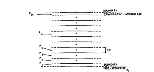
Analysis ProcedureThe numerical model developed by Lie [20] uses a finite difference approach to calculate temperatures in the slab. The analysis is based on a one-dimensional heat transfer model where the concrete slab is exposed to a standard fire from one side. For the calculation, the slab is divided into a number of elementary layers, as shown in Figure 3.2. The thickness of the layers isdx, with the exception of the boundary layers, which are 11- thick. Each layer is represented by a point P,,,. In the model, only a thermal analysis is carried out since the failure is governed by the temperature criterion for the reinforcement or on the unexposed side of the slab.
In the analysis, the temperature in each layer is assumed to be uniform and equal to that of the representative point. Initially, at time t = 0, the slab is at room temperature
(20°C). The temperature in the various layers of the slab is calculated for time t =At,
using the heat transfer equations outlined in the Appendix. Full details of the numerical procedure, as well as the derivations of the equations, are given by Lie [20]. The temperatures determined for t = Af are then used as the initial temperatures for the calculation of the temperatures at time t = 24f. This process is repeated until one of the failure criteria is met.
3.2.2 Material Propem-es
For the analysis, only the thermal properties of concrete, thermal conductivity and specific heat, as a function of temperature, are required. These properties are built into the program for four types of concrete, namely siliceous, carbonate, shale and pure quartz aggregate concretes. The mechanical properties, such as the stress-strain relationship, are not required since only a thermal analysis is carried out, however, the critical temperature for the reinforcement, at which the strength degradation reaches a specific value, has to be specified.
3.2.3 Computer Program
The various steps associated with the program execution are illustrated in the flowchart shown in Figure 3.3. The computer program was developed using FORTRAN. The input variables for the program include the slab thickness, the type of aggregate in the concrete and the type of reinforcement (FRP or steel). The output from the program consists of the temperature distribution through the thickness of the slab, as a function of
time, until one of the failure criteria is satisfied. The output also gives the resulting fire resistance of the slab in minutes. Alternatively, for a given fire resistance period, the minimum concrete cover thickness for the reinforcement (distance between the exposed slab surface and the bottom edge of the reinforcement) can be determined.
3.2.4 Program Verification
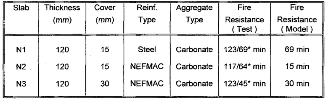
The computer model was evaluated by comparing predictions from the program with fire test data for FRP-reinforced concrete slabs. Table 3.1 shows the details of the slabs, designated N1 to N3, used for validation of the computer program. These slabs were tested by the NEFCOM Corporation [I91 and details are given in Section 2. All slabs were 120 mm thick and made with carbonate aggregate concrete. Two types of reinforcement, steel (Slab N1) and FRP, were considered in the slab tests. For the FRP- reinforced slabs, two concrete cover depths were used, while the steel reinforced slab had a 15 mm concrete cover thickness. The FRP reinforcement used in the slabs consisted of commercially available GFRP or GFRPICFRP NEFMAC grids.
Figure 3.4 shows comparisons of the temperature, at the depth of the
reinforcement, as a function of time. It can be seen that there is reasonable agreement between the predicted and measured temperatures. The predicted temperature-time relationship for Slab N2 (FRP, 15 mm cover) is close to the measured temperatures. Similarly, there is good agreement for Slab N3, with 30 mm cover.
When the fire resistance values from the tests determined using the temperature on the unexposed surface are compared to the values predicted by the model
(Table 3.1), large discrepancies are apparent. The measured and predicted fire resistances of the steel reinforced Slab N1 are 123 and 69 minutes, respectively. The measured and predicted fire resistances for the FRP-reinforced Slab N2 (1 17 and 15 minutes) and Slab N3 (123 and 30 minutes) indicate large variation.
The measured fire resistance of the steel reinforced Slab N1 was 69 minutes when the slab deflection limitations of the Japanese design standard were applied, as reported by NEFCOM [19]. This rating is in agreement with the predicted fire resistance of Slab N1-as calculated with the computer model. Similarly, the fire resistance of Slab N3 is 45 minutes, when deflection limits are accounted for, which is much closer to the 30 minutes predicted for Slab N3 than the 123 minutes resistance given without deflection limits.
On the other hand, even when deflection limits are considered, the predicted and measured fire resistances of Slab N2 are far apart. This can be attributed to the fact that, in the case of Slab N2, NEFCOM used only 40% of the load applied to Slabs N1 and N3. It is very unlikely that Slab N2 would have a rating of 64 minutes if subjected to the same load as the other slabs.
In the analysis using the computer program, failure is assumed to occur when the FRP reinforcement reaches a critical temperature of 250°C and steel reaches 593°C. While the critical temperature for steel is well established, the critical temperature for FRP is based on limited data and no specific data for NEFMAC was available. An increase of 20% in the critical temperature for FRP increases the fire resistance of the
model slab (30 mm concrete cover) from 30 to 40 minutes. Also, as described in the earlier Section, the analysis is based only on the thermal performance since the program cannot handle strength calculations.
If the FRP reinforcement used in the test slabs were treated with flame or heat retarding additives, the fire performance of these slabs could have been enhanced. Whether or not additives were used in the NEFMAC grids was not reported in the
literature. Due to a lack of experimental data, further evaluation of the program for FRP- reinforced concrete slabs could not be carried out.
3.3 Numerical Studies
The computer program was used to carry out parametric studies to determine the influence of various factors on the fire resistance of FRP-reinforced concrete slabs. The parameters include the type of reinforcement, the type of aggregate in the concrete mix, the concrete cover thickness and the slab thickness. It should be noted that the validity of the results from the parametric study is based on the assumptions used in the
development of the computer program.
3.3.1 Slab Characteristics
To study the effect of various factors on the fire performance of FRP-reinforced concrete slabs, three groups of slabs, designated A through C, were studied. The details
of these slabs are summarized in Table 3.2. These sets of slabs include both steel and FRP reinforcement and two concrete cover thicknesses. Group A contains three slabs which have the same characteristics as the slabs used to verify the computer model. Slabs A1 and A2 were used to study the effect of the type of reinforcement on the fire resistance of concrete slabs. Slabs in Group 6 were analyzed to study the influence of aggregate type in the concrete mix on the fire performance of concrete slabs. To determine the effect of concrete cover thickness on fire performance, slabs in Group C
were analyzed. Also, Slabs A3 and C2 were used to study the effect of slab thickness on fire performance.
3.3.2 Effect of Reinforcement
To study the influence of the type of reinforcement, on fire resistance, two slabs, one with steel (Al) and the other with FRP (A2), were analyzed. Both slabs were 120 mm thick, with a 15 mm concrete cover. The concrete was made with carbonate aggregate. The results from the analysis are shown in Figure 3.5 where the temperature of the reinforcement is plotted against time. The critical temperature at which failure is assumed to occur, for the steel and FRP reinforcement is also shown in the figure.
The fire resistance of the steel reinforced slab is 69 minutes while that for the FRP-reinforced slab is 15 minutes. The lower fire resistance of FRP-reinforced concrete slabs can be attributed to the lower critical temperature of FRP. Another factor that contributes to lower fire resistance of FRP-reinforced concrete slabs is the rate of increase of temperature in the slab which is very rapid until approximately 300°C when the rate decreases gradually. The reinforcement type has a significant effect on the fire
3.3.3 Effect of Aggregate Type
The influence of aggregate type on the fire resistance of FRP-reinforced concrete slabs was investigated by analyzing three slabs, B1, B2 and 83, made with siliceous, carbonate and quartz aggregates, respectively. All three slabs were 150 mm thick and had 40 mm concrete covers. The temperatures predicted from the computer program are shown in Fig. 3.6.
The type of aggregate has a moderate influence on the fire resistance of the slabs. Slab B1, with carbonate aggregate, shows a fire resistance of 44 minutes while for Slab B3 with quartz aggregate, the fire resistance is 35 minutes. Slab
B2,
made with siliceous aggregate failed at 40 minutes, 4 minutes earlier than the carbonate aggregate slab. The aggregate type has a significant effect on the rate of temperature increase. The temperature rise in the carbonate aggregate concrete is slower than that in the quartz aggregate concrete, resulting in higher fire resistance. This is mainly caused by the higher heat capacity of carbonate aggregate concrete, which, due to an endothermic reaction at about 700°C, increases to about ten times that of siliceous aggregateconcrete. This reaction is caused by the disassociation of dolomite present in the limestone.
The fire resistance values obtained above were based on the critical temperature for the FRP. For FRP reinforcement with a higher critical temperature, the influence of the aggregate type might be far more significant. If a critical temperature of 400°C is assumed for the FRP reinforcement, the siliceous aggregate concrete slab would give a fire resistance of 76 minutes compared to 90 minutes for the carbonate aggregate concrete. Thus, the fire resistance of carbonate aggregate concrete slabs would be 14 minutes higher than that of the slabs made with siliceous aggregate concrete and
24 minutes longer than quartz concrete. Based on this analysis, the higher the critical temperature limit of the reinforcement, the more significant the impact of the aggregate type on fire resistance.
3.3.4 Effect of Concrete Cover Thickness
To investigate the effect of the concrete cover thickness on the fire resistance of FRP-reinforced concrete slabs, five slabs, C1 to C5, were analyzed. All the slabs had a thickness of 200 mm and carbonate aggregate concrete. The cover thickness ranged from 20 to 60 mm, in 10 mm increments.
The temperatures obtained from the analysis are shown in Figure 3.7. It can be seen that the concrete cover thickness has a significant effect on the fire resistance of the slab. Higher concrete cover thickness delays the transmission of temperature to the reinforcement thereby enhancing the fire resistance. The fire resistance of Slab C1 (20 mm cover) is 19 minutes compared to 78 minutes for Slab C5 (60 mm cover).
As can be seen in the figure, the effect of the cover thickness is much more significant at temperatures below 300°C. If a one hour fire rating is required, then a concrete cover thickness of at least 50 mm is required for the 200 mm thick slab. This is much thicker than the cover thickness required for a steel reinforced concrete slab.
3.3.5 Effect of Slab Thickness
The influence of slab thickness on the fire resistance of reinforced concrete slabs was studied by comparing results from Slabs
A3
andC2.
Both slabs are of carbonate aggregate concrete and have30
mm of concrete cover. SlabA3
is120
mm thick while SlabC2
is200
mm thick. The predicted temperatures are shown in Figure 3.8.It can be seen from the figure that, in both slabs, the temperature rise with time follows the same trend. This is as expected since, for any given slab, the model assumes that the temperature rise at any point inside the slab will be the same regardless of the type of reinforcement used. The curve for Slab
A3
terminates at129
minutes because the concrete failure criteria has been exceeded at that point. However, for the FRP-reinforced slab, this makes no difference and both slabs show a fire resistance of30
minutes.In this case, slab thickness does not influence the fire resistance since the failure is governed by the critical temperature criterion for the reinforcement. However, if the unexposed temperature limit criterion governs the failure of slab (as in the case of steel reinforced slabs), then slab thickness will have significant effect on fire resistance. It can, therefore, be concluded that with FRP reinforcement, the slab thickness does not affect the fire resistance of the slabs.
3.4 Summary
A
numerical model in the form of a computer program was applied to the analysis of FRP-reinforced concrete slabs. The computer program is based on a one-dimensional heat transfer analysis to determine the temperatures across the cross- section of the slab. The computer program was validated with the limited test data available in the literature.
Using the computer program, parametric studies were carried out to evaluate the influence of various factors on the fire performance of FRP-reinforced concrete slabs. The effect of the reinforcement type on the fire resistance is significant, with the FRP- reinforced slabs having lower fire resistance compared to that of a slab reinforced with steel. The effect of aggregate type on the fire performance of FRP-reinforced slabs is moderate due to the lower critical temperature of FRP. The concrete cover thickness has a major effect on the fire resistance of FRP-reinforced slabs. The effect of slab thickness on the fire performance of the slabs reinforced with FRP is not significant.
Based on these limited parametric studies, higher fire resistance for FRP- reinforced concrete slabs can be obtained through higher concrete cover thickness to reinforcement and through the use of carbonate aggregate in the concrete mix.
Table 3.1. Details of slabs used for the validation of the numerical model
The first value indicates the fire resistance when the slab deflection limits were ignored. The second value shows the fire resistance when deflection limits were observed.
Table 3.2. Details of slabs used in the parametric studies Group A B C Fire Resistance (min) 69 15 30 40 44 35 19 30 43 59 78 Slab A1 A2 A3 B1 B2 B3 C1 C2 C3 01 C5 Reinf. Type Steel FRP FRP FRP FRP FRP FRP FRP FRP FRP FRP Aggregate TY Pe Carbonate Carbonate Carbonate Siliceous Carbonate Pure Quartz Carbonate Carbonate Carbonate Carbonate Carbonate Thickness (mm) 120 120 120 I 150 150 150 200 200 200 200 200 Cover (mm) 15 15 30
~-~~~~~
40 40 40 20 30 40 50 60Figure 3.2 Arrangement o f elementary layers in the model for
a
concrete slab. Variablesh-'
Calculation of f i n t m u r e N m w J Calculation of mossRoprries spional tempcratuns
Criteria
distribution. fire
nsistance and
Figure 3.3 Flowchan showing numerical procedure used in the computer program for calculation of slab fire resistance.
4. CONCLUSIONS AND RECOMMENDATIONS
Based on the information presented in this report, the following conclusions can be drawn.
4.1 Conclusions
1. There is very little information on the material properties of FRPs at elevated temperatures. Also, not much data is available on the behaviour of structural elements reinforced with FRP under fire conditions.
2. The FRP-reinforced concrete slabs have lower fire resistance in comparison to slabs reinforced with steel.
3. The factors which influence the fire resistance of FRP-reinforced concrete slabs are the concrete cover thickness and the type of aggregate in the concrete.
4. Based on limited parametric studies, higher fire resistance for FRP-reinforced concrete slabs can be obtained using thicker concrete cover for the reinforcement and by using carbonate aggregate in the concrete mix.
4.2 Recommendations
1. Data on the material properties of FRP (thermal, mechanical and deformation) at elevated temperatures is required.
2. The computer program used in the present study accounts for thermal analysis only and should be extended to include strength analysis.
3. Test data on the behaviour of FRP-reinforced structural elements exposed to fire is meagre. Further data is needed to verify the computer programs.
5.0 ACKNOWLEDGEMENTS
This research is part of a Joint Research Project between NRCC and Public Works and Government Services of Canada (PWGSC). The authors appreciate the technical and financial contributions of PWGSC.
6.0 REFERENCES
1. Bank. L.C.. "Prooerties of FRP reinforcement for concrete," Develo~rnents in Civil ~ n ~ i n e e r i n i , VO~. 42, Fiber-Reinforced Plastic (FRP) ~einforcement for Concrete Structures: Properties and Applications, Elsevier Science Publishers B.V., 1993. pp. 59-86.
2. Brown, J.E., Loftus, J.J. and Dipert, R.A., "Fire characteristics of composite materials - A Review of the Literature," NBSlR 85-3226, U.S. Dept. of Commerce, Aug. 1986,41 pp.
3. Gentry, T.R. and Hudak, C.E., "Thermal compatibility of plastic composite
reinforcement and concrete," CSCE, 2nd lnternat~onal Conference on Advanced Composite Materials in Bridges and Structures (ACMBS-II)
-
1996, Montreal, Canada, pp. 149-.4. Gerritse, A., "Specific features and properties of AFRP-bars," CSCE, 2nd International Conference on Advanced Composite Materials in Bridges and Structures (ACMBS-II)
![Table 1.1. Properties of various FRP composites and other materials [8]](https://thumb-eu.123doks.com/thumbv2/123doknet/14211141.481949/11.1191.109.1106.193.872/table-properties-various-frp-composites-materials.webp)

![Figure 1 .I. Longitudinal tensile loading of a continuous parallel fibre lamina [9]](https://thumb-eu.123doks.com/thumbv2/123doknet/14211141.481949/13.933.87.909.34.871/figure-longitudinal-tensile-loading-continuous-parallel-fibre-lamina.webp)
![Figure 2.3. Tensile stress-strain curves for CFRP at various temperatures [I I ]](https://thumb-eu.123doks.com/thumbv2/123doknet/14211141.481949/23.933.160.829.22.562/figure-tensile-stress-strain-curves-cfrp-various-temperatures.webp)