BWR COOLANT CHEMISTRY STUDIES
USING A RECIRCULATING IN-PILE LOOP
by
Bronislav Guimpelson
Submitted to the Department of Nuclear Engineering in Partial Fulfillment of the Requirements for the
Degree of
Master of Science
in
Nuclear Engineering
at the
MASSACHUSETTS INSTITUTE OF TECHNOLOGY
February 1995
@ Massachusetts Institute of Technology 1995
Signature of Author
Department of Nuclear Engineering Certified by
Michael J. Driscoll Thesis Advisor Professor Emeritus, Nuclear Engineering '-ý I
Certified by - ,
-. /7 Certified by
Otto K. Harling Thesis Advisor Professor, Nuclear Engineering 71 vI
Dr. Gordon E. Kohse Thesis Advisor Nuclear Reactor Laboratory Accepted by
Chairman, Department Committee on Graduate StudentsAllan F. Henry
I
I 4V 1
r
L
BWR COOLANT CHEMISTRY STUDIES
USING A RECIRCULATING IN-PILE LOOP
by
BRONISLAV GUIMPELSON
Submitted to the Department of Nuclear Engineering in partial fulfillment of the requirements for the Degree of Master of Science in Nuclear Engineering ABSTRACT
An in-pile loop to simulate the BWR coolant chemistry environment was substantially redesigned to allow operation in both once-through and recirculation modes. Runs were made to obtain comparative radiolysis data while the loop was run in both modes of operation, and to verify and extend N-16 data from the past campaigns.
Modernizations included a recirculation capability, new steam separator plenum to reduce water carryover and steam carryunder, relocation of the hydrogen peroxide sampling system to reduce gamma dose, installation of a new hydrogen peroxide sampler to reduce peroxide decomposition, a new in-core section to allow operation at reduced loop flow rates, relocation of in-thimble ECP sensors to a separate ECP plenum, replacement of titanium with stainless steel as the basic material of loop construction, employing Ge detectors for N-16 measurements and the Luminol method for peroxide measurements.
Baseline data were obtained for the recirculation mode of operation (normal water chemistry only) and once-through mode of operation (both normal and hydrogen water chemistry). The upgraded BCCL configuration now generates radiolysis products in better agreement with computer code predictions; but in general measured yields are about twice those predicted.
N-16 spectra were measured using Ge detectors on both water and steam lines. N-16 photopeaks were clearly distinguished from those of C-15; the maximum contribution of C-15 to total activities was shown to be 30%, although in most cases it is lower than 10%.
Carryover tests using chemical and radiochemical methods, demonstrated less than 0.1% carryover. Measurements of the ionic form of N-16 showed that N-16 is in cation form in steam and anion form in water.
A number of chemical additives were injected into the loop to investigate their effect on N-16 carryover and radiolysis product formation in the loop, as well as to verify data obtained during the previous BCCL campaigns. It was found that computed concentrations of H202 in the return streams are by a factor of 2 less than the measured values, suggesting the radiolysis yield G-values and chemical kinetics data may need some adjustment.
Thesis Supervisors:
Dr. Michael J. Driscoll
Title: Professor of Nuclear Engineering (Emeritus) Dr. Otto K. Harling
Title: Director, MIT Nuclear Reactor Laboratory Professor of Nuclear Engineering
Dr. Gordon E. Kohse
Title: Principle Research Engineer Nuclear Reactor Laboratory
ACKNOWLEDGMENTS
The present research is a further continuation of work studying BWR coolant chemistry, supported by EPRI, ESEERCO, Hitachi and Toshiba, most recently under the CORN project. This thesis constitutes the final topical report summarizing activity and experimental results during the last BCCL Campaign, supported by Hitachi and Toshiba.
The author wishes to express special thanks to Prof. O.K. Harling for giving him the unique opportunity to participate in this project and his permanent support and care. Cordial gratitude is addressed to Prof. M.J. Driscoll for his ideas and assistance at all stages of the project including run preparation, experimental work, results interpretations and analysis, and thesis write-up, as well as advising on issues outside of the scope of this research.
I wish to thank Dr. G. Kohse for his leadership which brought this project to successful completion. I want to express thanks to all members of the BCCL team for their tireless work and cooperation without which the author would never have been able to complete this work . Particularly, I wish to thank E. Cabello (Pakhan), Y. Ostrovsky, and B. Hilton for teaching me everything they know, for their everyday help and advice, support and attention; Prof. S. Simonson for his valuable ideas and help in preparations for this Campaign and discussions of the experimental results. I would also like to thank K. Hsueh for his assistance with water sample measurements, and L.W. Hu for her help with the Luminol method for hydrogen peroxide measurements. Special thanks are addressed to Y. Wada of Hitachi and T. Ohsato of Toshiba for their help in preparing for the BCCL run and participation in the first stage of the Campaign when the out-of-pile and loop shakedown tests were of the first priority. Y. Wada was also very helpful in the later part of the run, rendering assistance with the analysis of experimental data, preparations of chemical additives and running the Luminol equipment. Dr. E. Ibe of Hitachi and Dr. J. Takagi of Toshiba have been a continuous source of much valued advice.
I wish to thank the reactor operations and radiation protection teams for their help in running the reactor facility for this project in a safe and reliable manner; the machine shop for manufacturing different components of the loop and counseling on the design; and many other people who are not mentioned above for their cooperation.
I would especially like to thank my parents for their endless love, spiritual support, and understanding.
I dedicate this thesis to all nuclear professionals from the countries of the former Soviet Union.
TABLE OF CONTENTS
A B ST R A C T ... 2
ACKNOWLEDGMENTS ... 3
TABLE OF CONTENTS ... 4
LIST O F FIG U RES ... 7
LIST O F TA BLES ... 9
CHAPTER 1 INTRODUCTION ... ... 12
1.1 OBJECTIVE OF PRESENT RESEARCH ... 12
1.1.1 Forew ord ... 12
1.1.2 Current Experimental Campaign ... 12
1.2 Review of past BCCL work and modernization ... 13
1.2.1 System Design... 13
1.2.2 Experimental Results ... ... 17
1.3 ORGANIZATION OF THIS REPORT ... . 17
CHAPTER 2 FACILITY DESIGN ... ... 19
2.1 INTRODUCTION ... ... 19
2.2 OUT-OF-PILE SYSTEM ... ... 19
2.2.1 Charging Tank System ... ... 26
2.2.2 Pum p C abinet ... ... 26
2.2.3 Heat Exchangers ... 27
2.2.4 Recirculation Pump ... ... 28
2.2.5 Return Line Transit Section ... ... 30
2.2.6 Return Water Cleanup System ... 30
2.2.7 Chemical Injection System ... ... 31
2.3 THIMBLE AND INTERNALS ... ... 31
2.3.1 Thim ble ... 31
2.3.2 In-Pile Fluid System ... 33
2.3.3 In-Core Heated Section ... ... 33
2.3.4 Outlet Plenum/ Steam Separator ... 36
2.3.5 Instrumentation ... 36
2.4 NITROGEN-16 MEASUREMENT SYSTEM ... 42
2.4.1 Nitrogen- 16 Detectors ... 42
2.4.2 N-16 Data Acquisition System ... 42
2.5 ECP MEASUREMENT SYSTEM ... 42
2.5.1 Description of Reference ECP Sensors ... 43
2.5.2 Water Return Line Autoclave ... ... 46
2.5.3 Data Acquisition System ... ... 48
2.6 STEAM AND WATER EFFLUENT SAMPLING SYSTEM... 48
2.7 LEVEL CONTROL SYSTEM ... ... 48
2.7.1 Float ... 48
2.7.2 Coils ... 49
2.7.3 Electronics ... 49
2.8 HYDROGEN PEROXIDE SAMPLING SYSTEM ... 49
2.9 CONTROL/POWER/DATA ACQUISITION (DA) SYSTEM S ... 50
2.10 CHAPTER SUMMARY ... ... 52
CHAPTER 3 EXPERIMENT PROCEDURES ... ... 55
3.1 INTRODUCTION ... ... ... 55
3.2 LOOP OPERATION ... ... 56
3.2.1 Standby ... 57
3.2.2 Hot Single Phase ... ... 57
3.2.3 Boiling ... 58
3.3 SAM PLING ... 59
3.3.1 Hydrogen Peroxide Sample Tap ... 60
3.3.2 Steam and Water Sample Lines ... 62
3.3.3 Dissolved Oxygen and Hydrogen Sampling System ... 62
3.3.4 Charging Tank Sample Tap ... ... 63
3.4 N- 16 M EASUREM ENT ... 63
3.5 CHEMICAL ADDITION ... ... 65
3.6 ECP MEASUREMENT ... ... 66
3.7 TYPICAL RECIRCULATION RUN DESCRIPTION ... 66
3.8 CH APTER SUM M ARY ... 72
CHAPTER 4 OUT-OF-PILE TESTS ... ... 73
4.1 INTRODUCTION ... ... ... 73
4.2 OUT-OF-PILE LOOP DESIGN ... ... 74
4.3 EXPERIMENTS ... 74
4.4 RESU LTS ... 82
4.5 CHAPTER SUMMARY ... ... 83
CHAPTER 5 IN-PILE RECIRCULATION MODE RESULTS ... 84
5.1 INTRODUCTION ... ... ... 84
5.2 RESULTS ... 84
CHAPTER 6 IN-PILE ONCE-THROUGH MODE RESULTS ... 6.1 INTRODUCTION ... . ... 6.2 NW C RESULTS ... . ... 6.3 HW C RESULTS ... . ... 6.4 CHAPTER SUMMARY ... ... CHAPTER 7 SUMMARY, CONCLUSIONS AND
RECOMMENDATIONS ... ... 7.1 INTRODUCTION ... ... 7.2 FINDINGS RELEVANT TO BWR OPERATION ...
7.2.1 Radiolysis Chemistry and ECP ... 7.2.1.1 Once-Through Mode of Operation ... 7.2.1.2 Recirculation Mode of Operation ... 7.2.2 N-16 Carryover ... . ... 7.3 EFFECT OF CHEMICAL ADDITIVES ... 7.4 EFFECT OF C-15 ON N-16 MEASUREMENTS ... 7.5 FUTURE FACILITY APPLICATIONS AND CHANGES IN
DESIGN ... REFEREN CES... ... APPENDIX A BRIEF SUMMARY OF RUNS ... APPENDIX B EFFLUENT RESIDENCE TIMES FOR BCCL ... APPENDIX C PHASE SEPARATION IN BCCL EXIT PLENUM ... APPENDIX D CARRYOVER ... APPENDIX E CARRYUNDER ... ... APPENDIX F LUMINOL METHOD FOR H202 (H-2) ... APPENDIX G DETAILS OF EXTERNAL REFERENCE ECP SENSOR
FABRICATION ... .... ... ... G. I ASSEMBLY INSTRUCTIONS ... G.2 OPERATION AND MEASUREMENT GUIDELINES ... APPENDIX H FLOAT MANUFACTURING ... APPENDIX I LAY-UP PROTOCOL FOR THE BCCL RIG ... APPENDIX J EFFECT OF C-15 ON N-16 MEASUREMENTS ...
103 103 104 122 132 133 133 134 134 134 138 139 140 144 144 145 147 151 153 156 160 163 170 170 173 175 177 181
LIST OF FIGURES
Figure 1-1. BWR Coolant Chemistry Loop Configuration for the First Three
C am paigns ... 14
Figure 1-2. BWR Coolant Chemistry Loop Configuration for the 1993/94 Campaign ... 15
Figure 2-1. BCCL Out-of-Pile System in the 1992 Campaign ... 23
Figure 2-2. BCCL Out-of-Pile System in the 1993/94 Campaign ... 24
Figure 2-3. Auxiliary (Copper) Heater ... ... 29
Figure 2-4. Chemical Injection System... 32
Figure 2-5. In-Pile Fluid System... 34
Figure 2-5a. In-Pile Fluid System Assembly Schematic Showing Major Com ponents ... 35
Figure 2-6. In-Core Heater Block ... 37
Figure 2-7. New Steam Separator Plenum Design ... ... 39
Figure 2-8. Comparison Between Plenum Designs for 1992 and 1993/94 BCCL C am paigns ... 40
Figure 2-9. In-Thimble ECP Electrode Plenum ... ... 41
Figure 2-10. Schematic of External Ag/AgCl Reference Electrode ... 44
Figure 2-11. Toshiba ECP Electrode ... ... ... .. 45
Figure 2-12. Water Return Line Autoclave ... ... 47
Figure 2-13. Hydrogen Peroxide Sample Cooler ... .... 51
Figure 3-1. BCCL Sample Lines Configuration ... ... 61
Figure 3-2. Representative Steam Line Spectrum ... ... 64
Figure 3-3. Locations of the Cutoff Valves for Switching the BCCL from Recirculation Mode of Operation to Once-Through ... 68
Figure 4-1. Setup for the Out-of-Pile Tests... 75
Figure 5-1. Venturi Calibration under Cold Conditions { 770F (250C) ... 88
Figure 5-2. Venturi Calibration under Hot Conditions {5320F (2780C) } ... 89
Figure 5-3. Steam Orifice Calibration ... ... 90
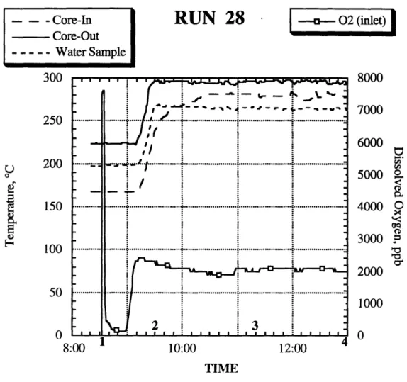
Figure 5-4. Run 28 Oxygen Concentration in the Recirculation Water... 92
Figure 5-5. Run 28 Recirculation Water Resistivity ... 93
Figure 5-6. R un 28 EC P ... ... 94
Figure 5-7. Run 28 Steam Baseline Spectrum ... ... 97
Figure 5-8. Run 28 Water Baseline Spectrum ... ... 98
Figure 5-9. Run 28 Steam Spectrum During Chemical Injection (3.6x10⁻⁵ M L iO H ) ... ... . . . 99
Figure 5-10. Run 28 Water Spectrum During Chemical Injection (3.6x10⁻⁵ M
L iO H ) ... ... 100
Figure 6-1. Run 32 Oxygen Concentration ... 110
Figure 6-2. Run 32 Hydrogen Concentration and ECP ... . 111
Figure 6-3. Run 32 Steam Baseline Spectrum ... 112
Figure 6-4. Run 32 Water Baseline Spectrum ... 113
Figure 6-5. Run 32 Steam Spectrum During Chemical Injection (10-4 M VOSO4) ... 114
Figure 6-6. Run 32 Water Spectrum During Chemical Injection (10-4 M VOS 4) ... 115
Figure 6-7. Run 32 Steam Spectrum During Chemical Injection (1.2x10⁻⁵ M VOSO4) ... 116
Figure 6-8. Run 32 Water Spectrum During Chemical Injection (1.2x10⁻⁵ M VOS0 4) ... 117
Figure 6-9. Experimental Setup for Determination of the Chemical Form of N-16... 121
Figure 6-10. Run 38 Oxygen Concentration ... 125
Figure 6-11. Hydrogen Concentration and ECP ... 126
Figure 6-12. Run 38 Steam Baseline Spectrum ... 128
Figure 6-13. Run 38 W ater Baseline Spectrum ... ... 129
Figure 6-14. Run 38 Steam Spectrum During Chemical Injection (10-4 M KNO2)... 130
Figure 6-15. Run 38 Water Spectrum During Chemical Injection (10-4 M KNO2) ... 131
Figure F-1. Setup of Luminometer ... 163
Figure F-2. Luminol Method Test for High Concentration H202 Samples ... 166
Figure F-3. Luminol Method Test for Low Concentration H202 Samples... 167
Figure F-4. Background Counts Due to Luminol (3.5 cc Luminol) ... 168 Figure F-5. Background Counts Due to DI Water and Luminol (1.5 cc DI Water
LIST OF TABLES
Table 2.1. List of Facility Modernizations ... ... 20
Table 2.2. List of the BCCL Components and References ... . 21
Table 2.3. List of Data Acquisition Signals ... ... 53
Table 2.4. List of Control Signals ... 54
Table 3.1. Standard Operating Parameters for the BCCL... 56
Table 3.2. Status of the Loop Valves for Different Modes of BCCL Operation ... 67
Table 3.3. BCCL Operation Procedures ... ... 71
Table 4.1. Summary Out-of-Pile and In-Pile Shakedown Run Descriptions... 76
Table 4.2. Peroxide Sampler Calibration Results ... 79
Table 4.3. Out-of-Pile Carryover Test Results ... ... 82
Table 5.1. Recirculation Mode of Operation, Summary of Experimental Results ... 85
Table 6.1. Once-Through Mode of Operation, Summary of Experimental Results under NWC (Normal Water Chemistry) ... 105
Table 6.2. N-16 Ionic Form Experimental Data ... 119
Table 6.3. N-16 Ionic Form Experimental Data (averaged) ... 119
Table 6.4. N-16 Ionic Form Experiment Results ... 120
Table 6.5. Comparison Between Once-Through Mode Baseline Data for 1992 and 1993/94 Campaigns ... 122
Table 6.6. Once-Through Mode of Operation, Summary of Experimental Results under HWC (Hydrogen Water Chemistry) ... 123
Table 7.1. Comparison Between 1992 and 1993 Experimental Data and Predicted Results for Once-Through Boiling and Non-Boiling Cases under NWC (loop flow rate was 25 g/s) ... 135
Table 7.2. Comparison Between 1992 and 1993 Experimental Data and Predicted Results for Once-Through Boiling and Non-Boiling Cases under HWC (loop flow rate was 25 g/s) ... 137
Table 7.3. Comparison Between 1993 Experimental Data and Predicted Results for Recirculation Boiling Case under NWC (loop flow rate was 15 g/s) ... . . ... 139
Table 7.4. Summary of 1991, 1992, 1993/94 N-16 Carryover Studies ... 141
Table A. 1. Brief Summary of Runs ... 147
Table B. 1. Residence Times for BCCL 1992 and 1993/94 Designs... 151
Table C. 1. Conditions and Parameters during the N-16 Measurements (1992 Cam paign) ... 154
Table D. 1. Out-of-Pile Carryover Test Results... 157
Table D.2. Water Sample Activities Results... 158
Table D.3. Steam Sample Activities Results ... 159
Table G. 1. Components and Equipment for Fabricating External Ag/AgCl Reference ECP Sensors ... 171
Table J. 1.1.Areas under Photopeaks of N- 16 and C- 15 for Steam and Water Phases During Baseline and LiOH Injection, 3.6x10⁻⁵ M (Run 28 Recirc.) ... 182
Table J. 1.2.Determination of the Effect of C-15 on N-16 Measurements During Baseline and LiOH Injection, 3.6x10⁻⁵ M (Run 28 Recirc.) ... 183
Table J. 1.3.Enhancement Factors for Run 28 (Recirc.) Including and Excluding C -15 ... 184
Table J.2. 1.Areas under Photopeaks of N-16 and C-15 for Steam and Water Phases During Baseline and VOS04 Injection, 10-4 M (Run 32) ... 185
Table J.2.2.Determination of the Effect of C-15 on N-16 Measurements During Baseline and VOS04 Injection, 10-4 M (Run 32) ... 185
Table J.2.3.Enhancement Factors for Run 32 Including and Excluding C-15... 186
Table J.3. I1.Areas under Photopeaks of N-16 and C-15 for Steam and Water Phases During Baseline and KNO2 Injection, 10-4 M (Run 38) ... 186
Table J.3.2.Determination of the Effect of C-15 on N-16 Measurements During Baseline and KNO2 Injection, 10-4 M (Run 38) ... 187
Table J.3.3.Enhancement Factors for Run 38 Including and Excluding C-15... 187
Table J.4.1 .Areas under Photopeaks of N-16 and C-15 for Steam and Water Phases During Baseline and K2MoO4 Injection, 10-4 M (Run 39, HW C) ... 188
Table J.4.2.Determination of the Effect of C-15 on N-16 Measurements During Baseline and K2MoO4 Injection, 10-4 M (Run 39) ... 189
Table J.4.3.Enhancement Factors for Run 39 Including and Excluding C-15... 189
Table J.5.1.Areas under Photopeaks of N-16 and C-15 for Steam and Water Phases During Baseline and K2MoO4 Injection, 10-4 M (Run 45, N W C ) ... ... 190
Table J.5.2.Determination of the Effect of C-15 on N-16 Measurements During Baseline and K2MoO4 Injection, 10-4 M (Run 45, NWC) ... 190
Table J.5.3.Enhancement Factors for Run 45 Including and Excluding C-15... 191
Table J.6. Half Life and Residence Times of Interest ... 192
Table J.8. Compton Background under N-16 and C-15 Peaks ... 195 Table J.9. Enhancement Factors Including Background ... 196
CHAPTER 1 INTRODUCTION
1.1 OBJECTIVE OF PRESENT RESEARCH
1.1.1 Foreword
Over the past several years an in-pile loop for simulation of the thermal hydraulic and radiolytic environment of a BWR has been designed, constructed and operated in the MIT Nuclear Reactor. Principal radiolysis product concentrations (02, H2, H202) as well as N-16 activity in the water and liquid phases can be measured, as can be the electrochemical corrosion potential of materials exposed to the loop aqueous environment. For the first three campaigns the loop was operated in a once-through mode, whereas the fourth campaign-the subject of the present report-involved both once-through and recirculation modes. The development of the facility and previous BCCL campaigns are described in the theses by J. Outwater (0-1), B. Rozier (R-1), B. Hilton (H-l), and in a comprehensive EPRI/ESEERCO/HITACHI/TOSHIBA summary report (E-1).
1.1.2 Current Experimental Campaign
The objectives of the subject 1993/94 Campaign were as follows:
1. To obtain comparative radiolysis data while the loop is run in both once-through and recirculation modes.
2. To verify and extend N-16 data from past BCCL Campaigns with new data obtained using Ge detectors.
3. To implement loop modifications to more closely simulate BWR conditions.
Several significant modernizations were implemented in the BCCL for the 1993/94 Campaign. In particular, the loop was equipped with the capability for both once-through and recirculation modes of operation, and titanium was replaced with
INTRODUCTION CHAPTER 1
316SS as the principal material of construction. The loop recirculation capability was successfully tested at the end of the 1992 Campaign, and some minor refinements were made prior to the 1993/94 recirculation runs. The main differences between the once-through and recirculation configurations are shown in Figures 1-1 and 1-2.
During the first half of 1993, loop design changes were developed and their feasibility was confirmed by appropriate tests. In the latter part of 1993 the new rig was assembled, carefully tested and, prior to in-pile runs, a series of out-of-pile tests were completed. Loop shakedown runs followed installation of the thimble with internals in the MITR core tank. During the first part of the 1993/94 experiments, loop characterization in its once-through mode of operation was carried out. Failure of the plenum level float interrupted the course of the experiments for more than one month following which recirculation mode runs were conducted. Considerable effort was devoted to loop baseline characterization during recirculation to match actual BWR conditions as closely as possible. After the recirculation baseline was established, different chemical additives were injected to study their effect on the behavior of N-16, radiolysis product generation, and electrochemical corrosion potential. When this part of the campaign was completed, the loop was switched back to once-through operation and additional chemical compounds of interest were injected.
1.2 REVIEW OF PAST BCCL WORK AND MODERNIZATION
1.2.1 System Design
Conceptual design of the BCCL and its modifications are described in detail in previous reports and theses. For the 1993/94 Campaign the design of the BCCL was further improved, so that the current loop configuration shown in Figure 1-2 represents a significant difference in comparison with the versions used in the 1990-1992 Campaigns. Before 1993 the loop was constructed of titanium (to reduce the background
FROM CHARGING TANK
-0)
HIGH PRESSURE PUMPS CHEMISTRY INJECTION CORE TANK BOUNDARY IN-CORE HEATER IN-CORE SECTION TO NON-REGEN HX, CLEANUPAND CHARGING TANK REGENERATIVE HEAT EXCHANGER ECP ELECT] AUTOCLAV
A AI!
FEED WATER HEATERN.
I I
RODE A1 SAMPLE TAPSSTEAM
STEAME
E
F_
LI
N-16 DETECTORS WATER SEPARATOR PLENUMJ
ECP
ELECTRODES OXIDE VIPLE PER SAFROM CHARGING
TANK TO NON-REGEN HX,'TA AMT TP
REGENERATIVE HEAT EXCHANGER ECP ELECTRODE AUTOCLAVE
SN-16
DETECTORS STEAM PLENA ECP ELECTRODES PEROXIDE SAMPLE SEPARATOR PLENUMFigure 1-2. BWR Coolant Chemistry Loop Configuration for the 1993/94 Campaign SAMPLE TAPS
concentrations of transition metals in the coolant) and was operated in a once-through mode without recirculation. Transition from titanium to stainless steel and operation in the recirculation mode were major changes implemented for the 1993/94 Campaign. Several other modifications were also introduced in the current design:
1. Modified steam separator plenum. The separator configuration was changed to reduce water carryover and steam carryunder.
2. The hydrogen peroxide sampling system was relocated above the separator to reduce its ambient gamma dose.
3. A new hydrogen peroxide sampler was designed to reduce peroxide decomposition, by decreasing the length of contact of coolant with hot tube walls.
4. The reference ECP electrodes were moved from the steam separator to the water letdown line. This increased the water flow rate past the electrodes, and avoided electrode operation in two-phase flow.
5. The in-core section mass was reduced using an aluminum block, with a minimum amount of molten lead, to thermally couple the Zircaloy water channel with the in-pile electrical heater. This decreased nuclear heating and allowed operation of the loop at a reduced flow rate, hence higher integrated dose to the coolant.
6. A new recirculation pump and an auxiliary heater were installed to better support the recirculation mode.
7. Ge gamma detectors were added for N-16 counting to replace the NaI detectors used in the past.
Special attention was also given to H202 measurements. For this purpose a more
precise technique (Luminol method) was tested, so that the validity of the CheMetrics® method used in earlier BCCL Campaigns could be checked and supplemented.
1.2.2 Experimental Results
Three campaigns were completed prior to the one reported here. In these runs data on ECP, H2, 02, H202, and N-16 were collected under both normal (NWC) and hydrogen (HWC) water chemistry in a once-through mode. The effect of adding different chemicals on suppression of N-16 activity in the steam line was carefully investigated. In general, adding hydrogenous organic compounds to the feedwater brought about an increase of N-16 carryover to the vapor phase, similar to that measured following hydrogen addition. In the final chapter of this report prior data will be integrated with the new results in the form of a comprehensive summary.
1.3 ORGANIZATION OF THIS REPORT
This report presents the results of the 1993/94 Campaign for the BCCL operated in its once-through and recirculation modes under normal water chemistry, hydrogen water chemistry, and chemical injection. A detailed loop description is presented here only for those components which were significantly changed since the previous campaign, as well as for new components. Only brief and very general attention is given to the loop elements which remained the same as before. Chapter 1 introduces the work and presents the main objectives of the current research. Chapter 2 describes the loop facility following the new modifications. Chapter 3 deals with experiment procedures. While operation in the once-through mode did not change significantly since the last campaign, the recirculation mode of operation was introduced, and its detailed description is presented in this chapter. Chapter 4 gives a description of the out-of-pile tests and their results. Results of the recirculation mode of operation are discussed in Chapter 5. And finally, results of loop once-through operation are presented and analyzed in Chapter 6. Conclusions and recommendations for future BCCL activity are
given in Chapter 7. Details of measurements and data analysis are contained in the appendices.
CHAPTER
2.1 INTRODUCTION
This chapter describes in detail only those loop modifications which were developed and implemented for the latest version of the facility. All other loop components and systems which remained unchanged are described at a more general level, since the details can be found in previous theses and reports.
The main loop modernizations were already pointed out in the introduction. They were done in support of several specific goals: to enable a recirculation mode of operation, to reduce water carryover into the steam line, and to decrease gamma heat to allow operation at reduced loop flow rates, etc. Here all changes will be presented in full. Many loop elements remained the same as during the previous campaigns: most of the out-of-pile system, and support systems comprising the sample and data acquisition systems. A list of the facility modernizations is presented in Table 2.1. Table 2.2 shows references where a detailed description of BCCL systems and components can be found.
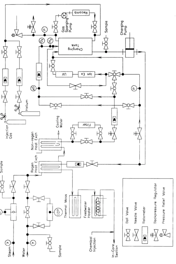
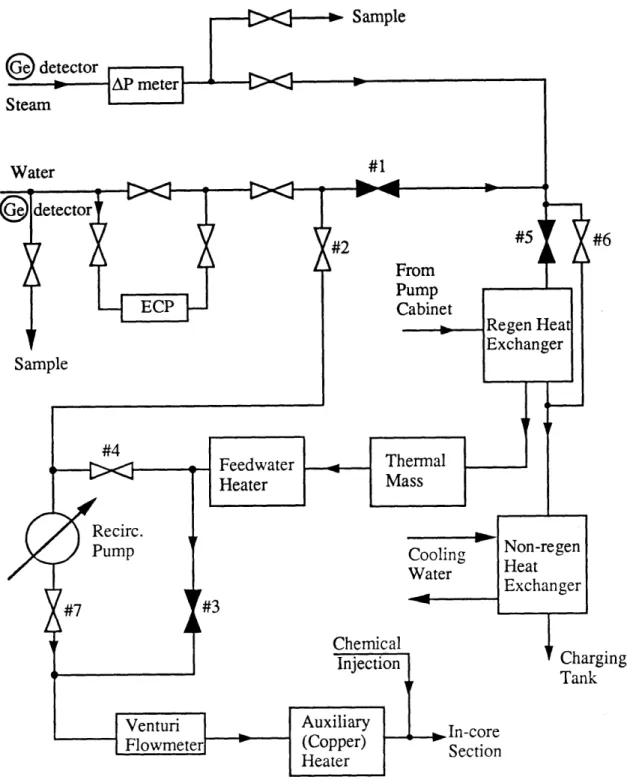
2.2 OUT-OF-PILE SYSTEM
The loop out-of-pile system consists of the charging tank system, pump cabinet, heat exchangers, steam and liquid letdown lines, return line transit section, including the recirculation line, the return water cleanup system, and the chemical injection system. The tube internal diameter remained the same as during the previous campaigns (0.48 cm), although the connecting tubes were made of stainless steel instead of titanium. Employing stainless steel allowed simulation of BWR fluid systems more realistically. The principle differences between the design of the out-of-pile fluid system for current
and past campaigns are shown in Figure 2-1 and Figure 2-2. FACILITY DESIGN
Table 2.1. List of Facility Modernizations
LOOP BCCL CAMPAIGN
SYSTEM 1992 1993/94
-Replaced feedwater -Ditto heater
-IX cleanup on return -IX cleanup on return and charging tank MAKEUP/ stream only streams
LETDOWN -Installed: recirculation pump, venturi flowmeter, auxiliary heater, low flow rate charging pump, advanced chem. injection pump
-Grounded sheath heater -Ditto
-Aluminum block in-core section, ECP plenum, enlarged steam/separator plenum, IN THIMBLE new H202 sampler, new ECP electrodes
SS instead of Ti
-Cherenkov detector for -No Cherenkov detector for N-13
INSTRUMEN-N-13
TATION
-Ion Chromatograph -No Ion Chromatograph
-Nal Detectors for N- 16 -Ge detectors for N- 16 and C- 15 -HYDRAN® H2 meter -Ditto
-Orbisphere® 02 low -Ditto flow meter for water
SAMPLING/ letdown line
ANALYSIS -New design of the H202 sampler -Luminol method
New and redesigned components include the recirculation line, recirculation pump, auxiliary heater, new charging tank system, and pump cabinet.
Table 2.2. List of the BCCL Components and References
LOOP COMPONENT REFERENCE
OUT-OF-PILE SYSTEM Charging Tank System
Charging tank O-1 (p.48)
Recombiner R-1 (2.2.1)
Gas sparging pump R-1 (2.2.1)
Cover gas flowmeters R-1 (2.2.1) Ion exchange columns O-1 (p.161)
UV tube H-1 (2.2.6)
Back-pressure regulator O-1 (p.161)
Pump Cabinet * (2.2.2)
CAT pump O-1 (p.50)
American LEWA pump * (2.2.2)
Micro pump * (2.2.2)
Back-pressure regulators O-1 (p.17 7)
Flowmeters on inlet lines R-1 (2.2.2),* (2.2.2) Return water flowmeters 0-1 (p. 178)
Ion exchange columns O-1 (p.161) Filter on return line H-1 (2.2.6) 02 Orbisphere sensor R-1 (3.3.3)
11H2 Orbisphere sensor R-1 (3.3.3)
HYDRAN H-1 (3.3.3)
Conductivity meter R-1 (2.6.3)
Flowmeter on the sensor line * (2.2.6) Non-regenerative heat exchanger O-1 (p.54)
Regenerative heat exchanger O-1 (p.54)
Thermal mass R-1 (2.2.3)
Feedwater heater O-1 (p. 164)
AE recirculation pump * (2.2.4)
Venturi flowmeter * (2.2.4, 5.2)
Auxiliary (copper) heater * (2.2.3)
ECP electrode autoclave H-1 (2.5.2), * (2.5.2)
CHEMICAL INJECTION SYSTEM
PulsaFeeder pump *(2.2.6)
Flowmeter on the PulsaFeeder pump suction line H-1 (2.2.7)
THIMBLE AND INTERNALS
Thimble O-1 (p.25)
In-core section *(2.3.3)
In-core electrical heater H-1 (2.3.3)
Outlet plenum/steam separator H-1 (2.3.4), *(2.3.4)
ECP plenum *(2.3.5)
LEVEL CONTROL SYSTEM 0-1 (p.36)
Float R-1 (2.7.1), *(App. H)
Coils O-1 (p.38)
Electronics O-1 (p.39)
ECP MEASUREMENT SYSTEM
ECP electrodes *(2.5.1)
ECP autoclave *(2.5.2)
Data acquisition system *(2.5.3)
HYDROGEN PEROXIDE SAMPLE SYSTEM
Sample cooler *(2.8.1)
Mixed cooling injection system H-1 (2.8.2)
Sample tap H-1 (2.8.3)
CONTROL/POWER/DA SYSTEM H-1 (2.9)
N-16 MEASUREMENT SYSTEM
Shielding blocks O-1 (p.52)
Detectors *(2.4.1)
Electronics O-1 (p.54)
Figure 2-1. Out-of-Pile Fluid System Schematic.
Cover gas bottles
Continued on next page
Figure 2-2. BCCL Out-of-Pile System in the 1993/94 Campaign Charging
rging k
2.2.1 Charging Tank System
The charging tank system, which is shown in Figure 2-2, was entirely rebuilt to simplify system operation, to make operation more reliable, and to provide more space in which to install new elements. The old charging tank system was disassembled, and new lines and valves were installed. It was also decided to take several system components out of the charging tank and to integrate them into the pump cabinet.
In order to support the recirculation mode of operation, a charging pump capable of providing low flow rates (50-200 cc/min) had to be installed. During the recirculation run shakedown at the end of the 1992 Campaign, the required low feedwater flow rate (150 cc/min) could be supplied by the main charging pump, but stability problems associated with flow oscillations were observed and attributed to operating the pump below its stability range. Hence, a new charging pump was obtained, and both the old and new pumps were installed together in a separate cabinet. From an operation standpoint, the new charging tank design did not introduce any differences from past practice.
The charging tank system comprises a reservoir of clean water, a cover gas injection and purge system, and a gas recirculation system that recombines dissolved oxygen and hydrogen. A detailed description of these systems is given in (H-1). A shelf was mounted on the charging tank to hold the installed oxygen and hydrogen Orbisphere® meters, and a HYDRAN® hydrogen meter.
2.2.2 Pump Cabinet
As has previously been mentioned, both the new and old charging pumps were installed in the subject cabinet. The pump cabinet built for the 1993/1994 Campaign includes three pumps: a high capacity charging pump-CATO piston pump (nominal flow rate of 5000 cc/min)- which is operated to provide feedwater for the once-through mode, an American LEWA® diaphragm pump (flow rate up to 220 cc/min) which provides
feedwater during recirculation mode operation, and a Micro® circulation gear pump to circulate charging tank water through dedicated ion exchange columns. The pump cabinet layout is shown in Figure 2-2.
There is a common feedwater line coming out of the charging tank reservoir and going to the distribution cross. Three lines start from the cross and go to either the CAT® pump, LEWA® pump, and/or circulation-Micro -pump. There is also a 3-way valve on the cleanup line in the cabinet used to fill the feedwater reservoir from a deionized water supply. All pump suction lines are equipped with shutoff valves to allow pump maintenance in-situ. In order to monitor flow rate, several flowmeters were installed on the pump cabinet. They are: a high capacity return line flowmeter (up to 2000 cc/min) and an inlet line flowmeter (up to 9000 cc/min) to measure flow rates when the loop is operated in its once-through mode, a low capacity return line flowmeter (up to 200 cc/min) to measure the return flow rate when the loop is operated in the recirculation mode, and a low capacity flowmeter on the LEWA® pump suction line to measure feedwater flow rate (up to 200 cc/min), again during recirculation mode operation. Two back pressure regulators and flow control valves are installed to control operational loop pressure and flow rate. A description of the system operation is given in Chapter 3.
2.2.3 Heat Exchangers
Several heat exchangers are employed in the loop. Their purpose is to bring water up to the desired temperature prior to the core section inlet. A detailed description of the ex-core heat exchangers has been given in previous reports and theses. Table 2.2 indicates where such information can be found. An extra heater was installed in the loop to support the recirculation mode operation.
At the very end of the last BCCL Campaign, the feasibility of loop operation in a recirculation mode was demonstrated. The only problem was relatively low core inlet temperature, which leads to an extension of the non-boiling length in the core. Therefore
to achieve a more realistic performance, a new heater was installed in the line leading to the MITR core tank. An additional benefit of this extra heater is that it allowed us to decrease the load on the feedwater heater and to permit its operation even in case of failure of one heating element. This is a very worthwhile advantage, since heating elements have a tendency to fail at high load.
The design of the new heater is shown in Figure 2-3. It consists of a copper block cut in halves and machined with grooves to contain two electrical heaters, and three passes of stainless steel tube. Heat is transferred from the surface of the heating elements to the water flowing inside the stainless steel tube. To provide reliable heat transfer, to avoid heating element failure, and to increase the thermal efficiency of the heater, a copper grease (see G-l) was applied to the outer surface of the tube and heating elements to couple them with the copper block. This auxiliary heater was thermally insulated and installed inside a support frame on the reactor top. Electrical connections were made to tie the heater in with the loop control system on the front mezzanine of the MITR-II.
2.2.4 Recirculation Pump
The recirculation pump, which allows recirculation mode of operation, was installed on the reactor top immediately downstream of the mixing Tee connecting the feedwater line and the recirculation line. The pump was mounted in a separate (from the main feedwater) line to permit maintenance while the loop is operated (in the once-through mode). An Autoclave Engineering® pump (see G-l) was chosen for this purpose. Since in the recirculation mode a large fraction of the return water stream is directed back to the in-pile thimble, the flow rate through the in-core section cannot be measured the same way as during the once-through mode using the return water flowmeter. To serve this goal, a venturi flowmeter was installed between the recirculation pump and auxiliary (copper) heater (see Figure 2-2). This flowmeter has a
SS Tube
--Wa
3.25"
1.25"
Cartridge Heaters Figure 2-3. Auxiliary (Copper) Heater
range of 0-5 psi for normal operating parameters (maximum flow rate 1500 cc/min), and it was used directly during recirculation mode runs, and to verify the pump cabinet flowmeter during the once-through mode runs.
2.2.5 Return Line Transit Section
A detailed description of the return line transit section can be found in the previous reports and theses, e.g. (H-1). During preparations for the 1993/94 Campaign several changes were implemented to allow operation in a recirculation mode. For this purpose a new line (see Figure 2-2) was installed to connect the existing water return line, right after the N-16 measurement system, to the feedwater line going to the in-pile thimble. Several shutoff valves were installed to easily switch from once-through to recirculation modes of operation. The steam orifice (maximum pressure drop of 5.0 psi), that was used in the previous campaigns, was calibrated both under atmospheric conditions and at nominal loop parameters (see Section 4.3 of Chapter 4).
2.2.6 Return Water Cleanup System
The return water cleanup system is shown in Figure 2-2. A set of ion exchange columns was installed in this subsystem. These columns are used to clean up loop return flow. In the 1993/94 Campaign once-through mode of operation, the return water flow rate was 1500 cc/min. A small fraction of the return flow is directed through a flowmeter and then through oxygen and hydrogen sensors mounted on the pump cabinet. After passing the sensors, the water flows through the columns before returning to the charging tank. This column was also used to purify the circulating water in the charging tank cleanup line. To avoid complications with operation and to simplify maintenance, a minimum number of valves are used. These valves are installed on a shelf on the pump cabinet. Several sample taps are provided to monitor the quality of charging tank water, return water, and circulation water.
2.2.7 Chemical Injection System
The chemical injection system was not changed since the last BCCL Campaign. It comprises a chemical injection pump, a flowmeter, bottles containing chemicals of interest, and a line going from the back mezzanine to the place on the reactor top where this line merges with the loop before entering the thimble. A detailed description of the system can be found in the references listed in Table 2.2. A new PulsaFeeder® pump replaced the older Milton-Roy® pump (see G-1). Its maximum capacity is 180 cc/min. Pump flow rate can be varied either by changing piston stroke or by changing current frequency. The chemical injection system is shown in Figure 2-4.
2.3 THIMBLE AND INTERNALS
Many changes were introduced in the design of the thimble and its internals during preparation for the 1993/94 Campaign. To decrease gamma heating of the in-core section and, therefore, to allow operation at reduced flow rates, the average density of the in-core section had to be reduced. As a result, lead was replaced by aluminum. The design of the new in-core section is described in Section 2.3.3 in greater detail. New internals were also designed to reduce potential water carryover into the steam line, the ECP electrodes were moved into a special plenum to avoid their operation in two-phase flow, and to decrease hydrogen peroxide decomposition.
2.3.1 Thimble
The BCCL thimble is designed to provide support for internals and to separate MITR coolant water from the loop coolant. Since the 1992 Campaign no significant changes in the thimble design have been introduced. A detailed description of the thimble design can be found in Ref. (H-1). Thimble dimensions can be found in (R-1).
To Core - I 1/4" Tubing Sample Chemical Injection PulsaFeeder Pump Flowmeter Bubbler
Figure 2-4. Chemical Injection System From
Feedwater
Heater Hater.
Aw-2.3.2 In-Pile Fluid System
The in-pile fluid system is made up of the same components as in previous campaigns. This system is shown in Figure 2-5. However, there are a number of differences implemented in the current design that allow closer simulation of the radiolysis chemistry of a BWR. First of all, all elements of the in-pile fluid system (except the in-core section) are made of stainless steel. Some design changes were also incorporated to place ECP electrodes inside a separate plenum ("ECP plenum"), and the peroxide sampler was completely redesigned to minimize peroxide decomposition in the sampling device. To decrease water carryover into the steam line, the steam separator plenum was significantly modified. The sections which follow focus on the following features:
1. Change from Ti to SS. 2. New peroxide sampler. 3. A plenum for ECP electrodes. 4. New steam separator plenum. 5. Features to reduce carryover.
2.3.3 In-Core Heated Section
One of the goals of the present campaign was to conduct experiments at reduced flow rates. For this purpose the in-core section was redesigned to generate less gamma heat than during previous campaigns. Since the main source of the gamma heating was the lead coupling the electrical heating elements with the in-core Zircaloy tube, lead was replaced by aluminum. After several unsuccessful attempts to create reliable thermal coupling between a slotted aluminum block and the electrical heating elements and Zircaloy tube it was found necessary to use a thin film of lead to fill in the remaining gap. This design allowed reduction of the lead mass by a factor of six and, therefore to decrease gamma heating by approximately 50%. The design of the new in-core section is
kluminum 'himble H202 Sample Water Out Line 0 cm ---
---In-Thimble
1/16" OD 0.0425" ID 107.2 cm...---... 5/8" OD 0.495" IDI
146.4 cm H202 Sample---228.0 cm 271.8 cm ---287 1 cm .. .,. . .. . .. . .. . 316SS 5/16" OD Fused quartz0.6 cm OD
0.4 cm ID ---44 cmTV
318.5 cm---175 cm .---Steam SOut Feedwater Line 316SSS0.25"OD
0.18" ID ECP Plenum..-
---114.3 cm... 13•0 cm
--- 14.4 cm ... 156.4 cm 316SS c---1.32"IOD Separator I Plenum --- 208.9 cm --- 225.7 cm Zircaloy0.31" OD
-... '. . " t U./.J IliFigure 2-5. In-Pile Fluid System
'Aw-.. - --, I. m It A .
0O
ECP Plenum
In-Core
Section
SteamOut
Peroxide
Sample
Line
Feedwater
Line
eparator
lenum
shown in Figure 2-6. Details of the new in-core section design can be found in the Safety Evaluation Report (S-I) presented to the MITR Safeguards Committee. All other elements, the Zircaloy tube and the heating element, were the same as before. During the campaign no failure of, or other problems with the new in-core section occurred.
2.3.4 Outlet Plenum/ Steam Separator
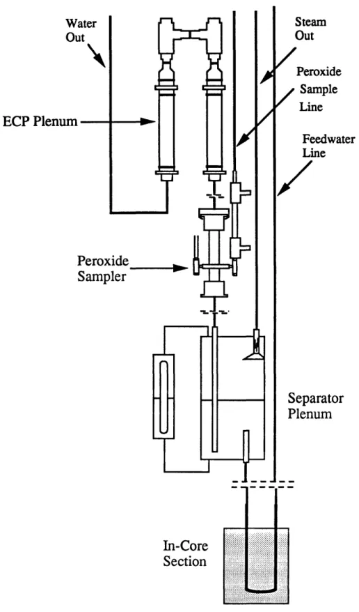
The BCCL outlet plenum/steam separator separates water from steam in the two-phase flow exiting the in-core section. It corresponds to the separator and dryer regions of a full scale BWR. The new plenum features an extended length (82 cm compared to 52 cm) to allow more volume for separation and to assure that water carryover into steam is less than 0.1%. For this purpose the steam exit tube was equipped with an impingement cone to prevent carryover of water droplets directed at the tube. The water exit line path was also redesigned to decrease the effect of gamma dose on either hydrogen peroxide production or decomposition. A quartz tube was introduced inside the water exit line to help reduce peroxide decomposition by elimination of water contact with a hot metal wall. The design of the new plenum is shown in Figure 2-7, and the differences in dimensions between the past and current designs are demonstrated in Figure 2-8.
2.3.5 Instrumentation
The two in-thimble ECP probes were removed from the outlet plenum and installed in a special ECP plenum designed to allow the probes to operate in a single phase medium. The ECP plenum design is shown in Figure 2-9. The two ECP probes used in the 1993/94 runs were provided by Toshiba Corporation.
A number of thermocouples were installed to measure in-core section inlet and outlet temperatures, lead bath temperature (to protect the aluminum block from excessive softening and failure), and to monitor peroxide sampler temperatures.
U N oo c5 Ira 00
0
In-Core Heater Block (Continued) C &
Ln
0-,O 0 dI 0 " S> L d d: EL Q . 0 OI G LO d t E O)aa
Z"ET--I,
Figure 2-6..Steam Exit Quartz Tube 0.6 cm OD 0.4 cm ID Inside SSTu (see Figure : 0.64 cm OD 0.48 cm ID
Figure 2-7. New Steam Separator Plenum Design
82cm
---Both separators have 1.32" ID (3.35 cm) 52cm 100% --- 42cm 50% --- 22cm
0%---1992 BCCL
Campaign
42cm 22cm 2cm0-100% Indicates
Level Detection
Range
100% 50% 0%1993/94 BCCL
Campaign
Figure 2-8. Comparison Between Plenum DesignsECP Electrodes
Insertion aseal Tee
ded Lnd Welded 3land Socket to 5/8" Tube OD
n) ID
Itraseal Socket Fitting Figure 2-9. In-Thimble ECP Electrode Plenum2.4 NITROGEN-16 MEASUREMENT SYSTEM
The N-16 measurement system is designed to measure N-16 gamma activity in the water and steam return lines. It has the same features as before, except that Nal detectors were not widely used in this campaign. They were employed mostly to normalize new data against the data obtained in the past. Two Ge detectors were installed to measure the gamma spectra from both the steam and water lines. A computer was connected to the MCA to save data for future analysis. Specifications of the new detectors are summarized in G-1.
2.4.1 Nitrogen-16 Detectors
As mentioned above, the two Nal detectors were replaced by Ge detectors. One of the reasons for this upgrade was to permit measurement of C-15, since one of the C-15 peaks lies in the vicinity of the 5.5 MeV peak of N-16. Employing Ge detectors allows determination of the effect of C-15 on the accuracy of N-16 measurements, and also to help understand the results of previous campaigns in greater detail.
2.4.2 N-16 Data Acquisition System
In order to provide for thorough analysis of N-16 data, an IBM computer was hooked up to the MCA. This permitted recording all data on disc for retention, later interpretation, and archiving.
2.5 ECP MEASUREMENT SYSTEM
The electrochemical corrosion potential (ECP) of a metal is the electrical potential between the metal and a reference electrode. In the BCCL, the ECP measurements are
conducted using two types of electrodes under different loop conditions including chemical addition.
2.5.1 Description of Reference ECP Sensors
Two types of reference ECP sensors were employed during the BCCL 1993/94 Campaign: 1) internal silver/silver-chloride (Ag/AgCI) sensors provided by Toshiba and 2) external silver/silver-chloride (Ag/AgC1) sensors with 0.1N KCI electrolyte solution fabricated at MIT. The two Toshiba sensors were placed in the ECP plenum (shown in Figure 2-11) located 0.1 meters above the steam separator plenum. The external Ag/AgCl sensors were located in an autoclave on the water line approximately 2.7 m beyond the thimble exit.
The Toshiba sensors are a standard design fabricated for use in BWR pressure vessels as in-core and recirculation line ECP monitoring devices. They are a self-contained unit with the Ag/AgCl electrode housed within a stainless steel body and use a sapphire plug as the semi-porous membrane allowing ionic contact with the water (see Figure 2-11). Because the corrosion current is so small, the current-carrying wire (1/8" MI cable) must be judiciously insulated from the outside stainless steel shell and this is done by a ceramic to metal braze developed for this technology. Because of the limited space for feedthroughs on the thimble lid, the MI cable was junctioned with copper wire in the 12" pod section in a manner similar to that used in the 1992 BCCL Campaign (H-1). ECP measurements made by the Toshiba Ag/AgCI reference sensors are corrected to the standard hydrogen electrode (SHE) scale by the following correlation,
EIntAg/AgC1 = Emeas + 642.9 - 1.645 x (T), mV SHE (2-1)
where T is the temperature in degrees Celsius.
The design of the second type, the external reference sensor, was developed by Peter Andresen at GE Research Laboratory in Schenectady and has been used in previous
tted with Silver Chloride
• protection
.e Teflon tubing
tion
60 -eE: C UC"-E
ug
00 0 0 0V
the basic design which consists of a zirconia plug as the semi-porous ionic conducting path, a Teflon heat shrink tube (which houses the Ag/AgCI electrode, the KCl fill solution and the zirconia plug forming a pressure boundary with the environment of interest) and the Conax® fitting which provides the pressure seal against the environment while ensuring an insulated wire for the current path. The electrochemical potential measured against a 0.1N KCl filled external Ag/AgCI sensor is corrected to SHE by the expression below (M- 1),
EextAg / AgCI = Emeas + 286.6 - 1.003 x (T -25) + 1.745 x 10⁻⁴ x (T-25)2 (2-2)
- 3.030 x 10⁻⁶ x (T-25)3 , mV SHE
where T is the temperature in degrees Celsius. During the out-of-pile tests, all external sensors produced meaningless results due to leakage of the fill solution out the top fitting (a Conax® with a Teflon® gland). This problem was eliminated by heat shrinking the tube where it seals on the silver rod to make a snugger fit around the silver rod, thereby reducing the likelihood of a leak. Details of fabricating these external reference sensors are specified in Appendix G.
2.5.2 Water Return Line Autoclave
The water return line autoclave was redesigned to simplify its maintenance and operability. It is shown in Figure 2-12. The autoclave was fabricated from four 1/2" Ultraseal® tees and a union gland similar to the original design, but ports for sensor employment were changed to face in the same direction and a drip-tray was installed. Two pairs of two tees welded together formed the body of the autoclave, thus minimizing the length, but maintaining flexibility. Compared to the design for previous campaigns the parallel port design for sensor employment improved the maintainability in the event of a leak which mandated valving out the autoclave, and the drip-tray localized possible leaks in case fittings loosened up during the rapid temperature changes experienced during cooldown.
on ao o~ cme b 50 a '-0) H a
2.5.3 Data Acquisition System
Signals from the ECP electrodes, both in thimble and autoclave, are read by a HP 3457 A Digital Voltmeter and recorded directly on the BCCL DA system which was installed on the reactor front mezzanine. (In the 1992 Campaign the ECP signals were recorded by a Hewlett-Packard computer and printed out every two minutes.) The ECP signals were also displayed on the computer screen, so that ECP behavior and trends could be observed in real time.
2.6 STEAM AND WATER EFFLUENT SAMPLING SYSTEM
The system was not changed since the 1992 Campaign. It consists of a sample cooler and water and steam sampling lines. The chiller bath was moved from the reactor top to the back mezzanine to reduce personnel dose, and the bath volume was increased to enhance cooling potential. Design of the system can be found in the previous reports.
2.7 LEVEL CONTROL SYSTEM
The level control system is necessary to maintain the level in the steam separator plenum in order to monitor stable boiling conditions and avoid water carryover in the steam line. A detailed description of the system is given in previous reports (see Table 2.2). This system was not changed significantly; only minor engineering changes were implemented to increase system reliability. The level monitoring range is shown in Figure 2-8.
2.7.1 Float
New floats were manufactured from quartz tubing of 8.0/6.9 mm OD/ID. After manufacture, the floats were tested at 1200 psi and 5500F for 8 hours and at 1500 psi at
room temperature for 24 hours. Those floats that withstood the tests were considered qualified for use in this campaign. However, after one month of loop operation (when the thimble was already in the core tank of the MITR) the float failed, so the thimble was taken out of the reactor, and the internals were taken out of the thimble to install a new float and continue the run. Appendix H describes in detail the fabrication of this key component, including changes implemented to make them more robust following the most recent failure incident.
2.7.2 Coils
Issues regarding the durability of the aluminum wire used for the coils have already been addressed in a previous thesis (H-1). In the present campaign the aluminum wire on the upper coil broke. As a result, the steam-water level in the outlet plenum was monitored and maintained in the lower part of the plenum using the lower coil only, i.e. at 40% of full height instead of the originally planned 50%. Changes to remedy this problem in future runs are recommended in Chapter 7.
2.7.3 Electronics
The electronics used to monitor the level in the outlet plenum remained the same as in the past. However a filter was introduced to smooth the signal from the coil, and the high frequency level oscillations formerly seen on the computer screen were eliminated.
2.8 HYDROGEN PEROXIDE SAMPLING SYSTEM
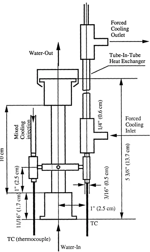
The purpose of this system is to allow sampling from the water return line for hydrogen peroxide analysis. The system consists of a peroxide sample cooler, a forced cooling heat exchanger, mixed injection cooling system, a sample line and tap.
The hydrogen peroxide sample cooler underwent further modifications during preparations for the 1993/94 BCCL Campaign. One of the major changes in the design was relocation of the sampling line. In the 1992 Campaign the water exit line left the steam separator plenum from the bottom (towards the in-core section), one potential factor leading to relatively high measured H202 concentrations. During this campaign the steam plenum was redesigned, so that the water line exits the separator from the top, thereby avoiding high neutron and gamma doses. The peroxide sampler is located where the water line leaves the steam plenum.
Figure 2-13 shows the configuration of the new peroxide sampler. A 3/16" fitting is welded to the water line right after the water leaves the steam plenum. In this fitting the sample water is mixed together with the cooling water (so that the mixed temperature drops below the -4000F-threshold above which significant peroxide decomposition
occurs) and goes to the tube-in-tube heat exchanger for further cooling. Two thermocouples are provided to measure the temperature of the cooling water before mixing, and the mixed temperature. Dimensions of the sampler are given in the same figure. Design of the mixed cooling injection system and sample tap is discussed in (H-I) in detail.
2.9 CONTROL/POWER/DATA ACQUISITION (DA) SYSTEMS
The BCCL control system allows monitoring of thermocouple readings, level in the steam separator plenum, thimble humidity, pressure, and the power level of the in-core heater. During this campaign, the ECP electrodes were also hooked up to the DA system computer. All these data were recorded on the computer hard disc. A detailed description of the control system and alarm signals can be found in Ref. (H-l). The current BCCL campaign also featured the recirculation mode of operation, and, therefore, new auxiliary copper heater and recirculation pump controls were provided; they were
Water-Out
Forced Cooling Outlet
Figure 2-13. Hydrogen Peroxide Sample Cooler
0
Forced Cooling Inlet
placed on the reactor front mezzanine. A venturi flowmeter was installed on the reactor top downstream of the recirculation pump to measure recirculation flow rate. The signal from the venturi flowmeter was sent to a pressure drop monitor. Another signal was sent from the steam orifice to determine the flow rate through the steam line to calculate steam quality. A revised list of data acquisition and control signals is compiled in Table 2.3 and 2.4.
2.10 CHAPTER SUMMARY
As discussed in this Chapter, the BCCL consists of the following systems: out-of-pile system, thimble and internals, N-16 and ECP measurement systems, steam and water effluent sampling system, level control system, hydrogen peroxide sampling system, and control/power/data acquisition system. These systems have been described in great detail in (0-1), (R-1), (H-1), and previously cited EPRI Report (E-1); in the present write-up attention was given mostly to recent loop modifications.
Table 2.3. List of Data Acquisition Signals
# DA SIGNAL SIGNAL DESCRIPTION
1 CORE-IN Coolant temperature at the in-core section inlet 2 CORE-OUT Coolant temperature at the in-core section outlet 3 SAMPLE BLK Temperature of the mixed cooling injection
measured prior to mixing with the sample stream 4 RHX-TUBE-IN Coolant temperature at the tube-inlet of the
regenerative heat exchanger
5 RHX-TUBE-OUT Coolant temperature at the tube-outlet of the regenerative heat exchanger
6 RHX-SHL-IN Coolant temperature at the shell-inlet of the regenerative heat exchanger
7 RHX-SHL-OUT Coolant temperature at the shell-outlet of the regenerative heat exchanger
8 LEVEL-DET Water level in the steam plenum
9 DELTA-P Pressure drop across venturi or steam orifice 10 WATER-COND Water conductivity
11 WATER-PH Water pH 12 PRESSURE Loop pressure
13 POWER In-core section heater power 14 OXYGEN Oxygen concentration 15 HYDROGEN Hydrogen concentration
16 ECP1 Toshiba in-thimble ECP sensor 17 ECP2 Toshiba in-thimble ECP sensor
18 ECP3 Ag/AgC1 MIT ECP sensor in autoclave 19 ECP4 Ag/AgCl MIT ECP sensor in autoclave
Table 2.4. List of Control Signals
CONTROL SIGNAL NOMINAL ALARM
VALUE
In-core section lead bath high temperature 4150C (7800F) 4270C (8000F)
Low BCCL pressure 7.0 MPa 3.55 MPa
Low water level in the charging tank 55 L 30 L
High thimble humidity 5% 40%
Low thimble pressure 12 psig 10 psig
Low in-core section heater current 5 KW 0.5 KW Low water level in out-of-pile test tank 4.58 m (15 ft) 3.66 m (12 ft) Regenerative heat exchanger tube outlet 2770C (5300F) 2880C (5500F)
high temperature during experimental run
Feedwater heater outlet temperature 2600C (5000F) 2880C (5500F) Auxiliary (Copper) heater outlet 2820C 5400F) 2880C (5500F)
temperature
EXPERIMENT PROCEDURES
3.1 INTRODUCTION
The BCCL experiment procedures did not undergo significant changes since the 1992 Campaign. The loop was operated at hot standby, hot single phase, and boiling in the once-through and recirculation modes. Primary data included the oxygen and hydrogen concentrations in the charging tank, mixed-return line and water sample line. N-16 activity was measured in the steam and water lines with Ge detectors. In several runs Nal detectors were used to obtain results for the 1993/94 Campaign comparable with those recorded in the past. Hydrogen peroxide was measured in the loop water letdown line, in the charging tank, and the mixed return. Electrochemical corrosion potential (ECP) was measured in the in-thimble ECP plenum and the external autoclave. Water conductivity was measured by using an in-line conductivity meter. Data were gathered both on-line and in batch samples. Several samples were taken for ICP analysis.
All actions performed by the loop operators were recorded, as in the past, in the BCCL Run Log on the back-mezzanine Mac computer, the IBM-386 data acquisition (DA) computer located on the front mezzanine, and on the log sheets. For more details refer to (H-1). The Hewlett Packard computer previously used for processing ECP signals was eliminated in this campaign, and the signals were sent directly to the front mezzanine DA computer, and trends displayed on the monitor. As before, the cover gas in the charging system was varied to simulate both NWC and HWC conditions.
To permit operation in the recirculation mode, the BCCL featured new components, as described in the previous chapter. A typical recirculation run will be presented later in this chapter. A list of standard operating parameters for the BCCL is given in Table 3.1.
Table 3.1. Standard Operating Parameters for the BCCL
PARAMETER HOT SINGLE PHASE BOILING
Coolant Flow Rate (Once-Through) 1500 cc/min 1500 cc/min Coolant Flow Rate (Recirculation) 900 cc/min 750-1000 cc/min Feedwater Flow Rate 200 cc/min 80-150 cc/min
(Recirculation Mode Only)
Loop Pressure 7.0 MPa (1000 psi) 7.0 MPa (1000 psi) Core Inlet Temperature 2330C (4500F) 2800C (5350F)
Core Outlet Temperature 2750C (5300F) 2900C (5550F)
In-Core Lead Bath Temperature 3600C (6800F) 4150C (7800F)
Reactor Power 4.5 MW 4.5 MW
Outlet Plenum Water Level 100% 40%
Steam Exit Quality (Once-Through 0% 10% Mode)
Steam Exit Quality (Recirculation 0% 15% Mode)
In-Core Heater Power 3.5 KW 5.0 KW
Feedwater Heater Outlet 221 C (4300F) 2630C (5050F)
Temperature
Feedwater Heater Current 10 A 20 A
Auxiliary (Copper) Heater Current 10A 20 A
3.2 LOOP OPERATION
Three operation regimes in the once-through mode of operation-standby, hot single phase, and boiling-have already been discussed in detail in previous reports (R-1) and (H-1). The only significant change for this campaign was the use of an auxiliary