Publisher’s version / Version de l'éditeur:
Proceedings of the Eighteenth International Conference on Surface Modification
Technologies,Dijon, France, November 15-17, 2004 >, 2004
READ THESE TERMS AND CONDITIONS CAREFULLY BEFORE USING THIS WEBSITE.
https://nrc-publications.canada.ca/eng/copyright
Vous avez des questions? Nous pouvons vous aider. Pour communiquer directement avec un auteur, consultez la
première page de la revue dans laquelle son article a été publié afin de trouver ses coordonnées. Si vous n’arrivez pas à les repérer, communiquez avec nous à PublicationsArchive-ArchivesPublications@nrc-cnrc.gc.ca.
Questions? Contact the NRC Publications Archive team at
PublicationsArchive-ArchivesPublications@nrc-cnrc.gc.ca. If you wish to email the authors directly, please see the first page of the publication for their contact information.
NRC Publications Archive
Archives des publications du CNRC
This publication could be one of several versions: author’s original, accepted manuscript or the publisher’s version. / La version de cette publication peut être l’une des suivantes : la version prépublication de l’auteur, la version acceptée du manuscrit ou la version de l’éditeur.
Access and use of this website and the material on it are subject to the Terms and Conditions set forth at
Wear Behaviour of Al-based Composite Coatings Obtained by Laser
Cladding and Reinforced with WC, TiC and SiC Particles
Dubourg, L.; Ott, A.; Hlawka, F.; Cornet, A.
https://publications-cnrc.canada.ca/fra/droits
L’accès à ce site Web et l’utilisation de son contenu sont assujettis aux conditions présentées dans le site LISEZ CES CONDITIONS ATTENTIVEMENT AVANT D’UTILISER CE SITE WEB.
NRC Publications Record / Notice d'Archives des publications de CNRC:
https://nrc-publications.canada.ca/eng/view/object/?id=06202f61-830b-4cca-871f-b4274cf37f8e https://publications-cnrc.canada.ca/fra/voir/objet/?id=06202f61-830b-4cca-871f-b4274cf37f8eIMI2004-106917-G CNRC 47577
Wear behaviour of AI-based composite coatings obtained by laser cladding
and reinforced with WC, TiC and SiC particles.
L. DUBOURGa,1,A. OTIb, F. HLAWKAc,A. CORNETd
a Aluminium Technology Centre, National Research Council Canada, 501, Boul. de I'Universite, Saguenay (Quebec) G7H 8C3 Canada. E-mail: laurent.dubourg!a2cnrc-nrc.g:c.ca
b. IFSW - Institut fUr Strahlwerkzeuge, Pfaffenwaldring 43, 70569 Stuttgart Germany. The Institute belongs to the University of Stuttgart. E-mail: agnes.ott@daimlerchrvsler.com
CLaboratoire d'lngenierie des Surfaces de Strasbourg, ENSAIS, 24 bd de la victoire, 67000 Strasbourg, France.
E-mail: f.hlawka@insa-strasbourg.fr
d Laboratoire d'lngenierie des Surfaces de Strasbourg, ENSAIS, 24 bd de la victoire,67000
Strasbourg,France.E-mail: a.comet@insa-strasbourg.fr
1Corresponding author: Tel. +1418 545-5098; Fax +1418545-5345 (L. Dubourg)
ABSTRACT
This study investigates the influence of the composition and the reinforcement nature of laser cladded metal-matrix
composite (MMC) coatings onto the hardness and the adhesive wear behaviour. Laser cladding was carried out on an
Al-Si-Mg substrate using a cw Nd:YAG laser and a coaxial powder injection system. Coatings were made of an AVSi matrix containing 12 wt.% Si and reinforcements of WC (spherical or crushed), TiC or SiC particles with a volume fraction ranging from 0 to 50 %. Samples were characterised using optical microscopy, hardness measurement and adhesive wear testing (ball-on-disk device). Reinforcement ratio increased the bulk coating hardness up to a maximum value of280 HVs regardless of the reinforcement particle nature. As the volume fraction of TiC, WC or SiC increases, adhesive wear damage evolved from severe to mild wear and the worn volume can be
reduced by a 20 factor. Regardless of the reinforcement particle type, the higher wear resistance was observed with a reinforcement ratio of 35 vol. %. The carbide nature did not seem to have a great influence, neither its shape. Although the mechanical characteristics of the different reinforcement particles are dissimilar, no significant difference could be observed between laser cladded MMC coatings containing TiC, SiC or we.
1.0 INTRODUCTION
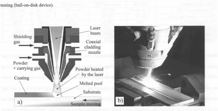
Aluminium alloys offer important advantages in terms of their specific weight, corrosion resistance and thermal conductivity. However, they have poor tribological characteristics. This drawback can be corrected using laser surface treatment, which does not affect the global properties of the bulk material. In the case of aluminium alloys, two surface treatments have been thoroughly investigated: laser alloying and laser cladding. Laser alloying consists in melting the aluminium surface with a laser beam while adding element. Laser cladding, as studied in the present work, consists in covering the substrate surface with a coating of a different nature as illustrated in Fig. I.a. This process can be carried out in different ways: wire feeding and lateral [1] or coaxial [2] powder injection (see Fig. l.b). In the case of powder injection, the cladding powder is injected into the laser beam by an inert gas flow.
The energy delivered by the laser is absorbed both by the powder stream and the substrate material. This enables the
melting of the in-flight particles and the fusing of the powder onto the substrate surface. A clad is formed by moving the sample under the laser beam. An uniform layer is obtained by partially overlapping individual clads. A slight dilution of the cladding material in the substrate generates a perfect metallurgical bonding between them. Over the last fifteen years, many studies on aluminium laser surface treatment have been carried out with the objective of improving the mechanical characteristics of coatings (hardness, elastic modulus, wear resistance). Several authors have already investigated the formation ofintermetallic aluminium compounds (alloys AI-Ni [3], AI-Fe [4], Al-Cu [5], Al-Mo [6] and Al-Cr [7]) and silicon precipitation in Al-Si alloys [8]. Another field of study consisted in the development of metal matrix composites (MMC) coatings. In laser surface treatment, these materials are composed of hard reinforcement particles distributed in a softer metal matrix. In the case of aluminium, the reinforcements are more often silicon carbide [9] and titanium carbide [10]. In the present study, composite coatings were made of an Al/Si matrix containing 12 wt.% Si and reinforcements of WC (spherical or crushed), TiC or SiC powders with a volume fraction ranging form 0 to 50 %. The laser cladding is carried out using a coaxial powder injection system
(see Fig. l.b). Samples were characterised using optical microscopy, hardness measurement and adhesive wear testing (ball-on-disk device).
Shielding
gas
.
Laser beam
Figure 1: principle oflaser cladding with coaxial powder injection.
2.0 EXPERIMENTAL PROCEDURE
Laser cladding was carried out using a continuous wave 4000 W Nd:YAG laser of 1,064 /lm wavelength and a 600 /lm diameter optical fiber. A lens with a 280 mm focal length focus the laser beam. The selected parameters were as follows: the laser beam power was adjusted to 3700 W on the workpiece surface, with a spot diameter of 4 mm; the calculated power density is then 290 W.mm-z.The angle between the laser beam and the surface sample was set at 80°. Normal incidence was not used to avoid the risk of beam reflection, which could damage the optical fibre or the laser cavity. Samples were placed on an X-Y table. The sample translation velocity was varied from 0.4 to 0.6 m.min-1depending on the coating composition. Laser treated specimens were circular to allow wear tests with a ball-on-disk-type device. Substrates were composed of AllO% Si 1% Mg (wt.%) and their size was 060 x 8 mm. Their surface was sand-papered using a l20-grit SiC paper followed by cleaning with acetone prior to laser treatment. Powders of pre-allied AVSi matrix (12 wt.% Si content) and reinforcement particles were premixed prior the injection with a volume fraction ranging form 0 to 50 % (see Table 1). These were injected inside the laser beam at a
Table 1: Characteristics and mechanical properties of used materials [11].
Microstructure examination was performed by optical microscopy after mechanical polishing (diamond with 1 f..lm grain size) and chemical etching using Keller's reagent. Vickers hardness measurements were performed with a load of 50 N on the coating surface after machining. A ball-on-disk-type tribometer was used for wear experiments under dry-sliding conditions. The laser coating was machined to obtain a flat surface of about 2 mm wide (Ra = 6 f..lm)and cleaned with acetone. A tungsten carbide ball (diameter of 6 mm, hardness of 1400 HVo.2and load of 5 N) slided on
the machined circular coating as the substrate was rotated. The tangential speed was 0.4 m.s.l and the sliding distance
was fixed at 1600 m. The wear experiments were not carried out under a controlled atmosphere. Wear was characterised using the worn volume of the specimen and by observing the wear tracks. The worn volume was calculated fTomthe coating density and the sample mass loss (measured with an accuracy of::!:0.1 mg). The coating density can be adequately estimated using the law of mixture between the matrix and the carbides [12]. This approximation was valid, as the coatings were not porous. On the other hand, comparison of mass loss is not significant due to the large difference of used carbide densities (see Table 1). Moreover, direct worm measurement
was not possible due to the strong damage observed on the low carbide content coatings. Observation of wear scars
was performed by microtopography and SEM. The mass variation of the WC ball was not measured. Microtopographic data of wear tracks were obtained by an extended field confocal microscope with a vertical resolution of 0.01 f..lmand lateral resolution of2 f..lm.The topography was measured on a 5 x 3 mm2 surface, with a sampling step of2 f..lmin the horizontal plan. The SEM used was a Phillips type XL30.
Nature of powders Al 12Si Spherical WC Crushed WC TiC SiC
Composition (wt.%) 12 Si 88 AI 99,5 WC 99,5 WC 99,5 TiC 99,5 SiC
Particule size range (f..lm) 45-90 50-150 50-150 50-150 50-150
Melting point (°e) 550 2870 2870 3250 2700
D(gjcm3) 2,7 14,9 14,9 4,95 3,2
Hardness (HV 02) 80 2500 2500 3200 3350
3.0 RESULTS AND DISCUSSION
3.1 Microstructural analysis
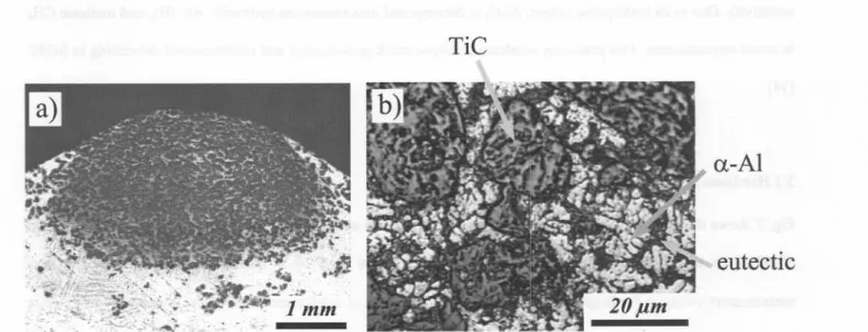
Coatings were produced with a AUSi matrix containing 12 wt.% Si and reinforcements ofWC (spherical or crushed), TiC or SiC powders with a volume ftaction ranging form 0 to 50 %. The coatings were ftee of pores or cracks and showed a metallurgical bonding to the substrate. The typical coatings were approximately 1.5 mIDthick and 4 mm wide. All coatings showed a homogeneous carbide distribution, as shown in Fig. 2.a. Moreover, these coatings were uniform: microstructure scale and type were similar through the entire coatings.
TiC
Figure 2: (a) Cross section of AI l2Si- 50vol.%TiC coating produced wi
I
powder feed rate of 10 g.min-1(b) Micrograph of AI 12Si- 50vol.%TiC coatibg.
1
I
I
For TiC reinforcement, microstructures were composed of intact TiC parti~les, white a-AI primary dendrites and a
I
dark AUSi eutectic component (see Fig. 2.b). The single eutectic microstructure predicted by the binary diagram at 12% Si was not observed. This phenomenon can be explained by the rapJ solidification rate peculiar to the laser
pmoo", Undo<dynamic conditio",. woe, of phMe exi_ce can be modifif and the eutectic composition is shifted to the silicon side of the diagram in case of rapidly solidified AI-Si alloys [13]. Similar phenomenon can be observed in laser treated Al-Cu alloys [5]. Microscopic observations revealed no supebcial dissolution of the TiC particles in
1
the aluminium matrix nor the presence of any A4C3 aluminium carbides aSlpreviously observed by Lietchi et al. in AI-TiC laser cladding [9]. Even though the TiC melting temperature is hig~er than the boiling point of aluminium,
this can be p"",ible " tbe abso<ptioncoefficient ofTiC at tbe lase, waveletgtb is tbree time, the ooe of aluminium
a-AI
WC. This phenomenon can be explained by the A14C3carbide precipitation observed previously. This led to matrix
strengthening and then to a bulk hardness increase.
300 300
'.
---
250 >'"~
~
200 (J) c:: "0 tv 150 ..c: 0 .... c.>~
100u.
--- 250 >'" :I:-;;
200 If) (J) c::~
.... 150 ..c:e
~ 100,
:2
/ // ,/oF '. ~ , // ~.
r-T-iT - r-'t'-ib)
~
~
50! , , , , 20 30 40 50 0 10 20 30 40 50Carbide ratio (voL%) Carbide ratio (voL%)
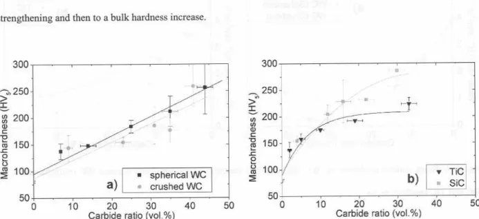
Figure 3: Vickers hardness evolution vs. WC, SiC and TiC contents. Each value is an average of six measurements
+t/:~:~>/4-~v// I'
.
spherical WC.
a)
I .
crushed WC50
0 10
takenwith a load of 50 N on the coating surface after machining.
3.3 Wear experiments
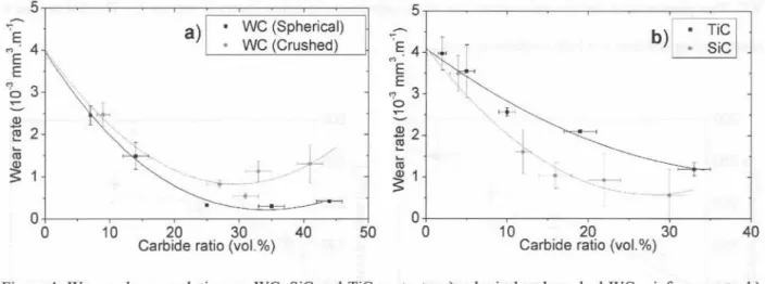
Wear resistance was characterised using the worn volume of the specimen: Fig. 4 shows these results as a function of
WC, SiC and TiC content. Increase of carbide content improved the wear behaviour of the coatings: the wear rate
was decreased by a 20-ratio. In spite ofthe heterogeneous properties of the carbides used (see Table 1), no significant
difference was observed on the wear resistance. This can be explained by the strong hardness difference between the
carbides and the Al/Si matrix (see Table 1). Nevertheless, the spherical WC particles showed a higher wear resistance than the crushed WC ones. In fact, the angular shapes of the crushed particles are more sensible to the failure and to the picking out the matrix. A similar phenomenon has been observed by Lagrange [16] for the laser cladding of steel substrate with WC reinforcement. For all MMC coatings, the lowest wear rate is observed at around 35 vo1.% carbide reinforcement (see Fig. 4). Two behaviours are noted on the wear tracks:asevere adhesive wear that evolves to a mild wear when the carbide ratio increases. The mild/severe wear transition is observed between 23 to 30 vo1.%for spherical WC reinforcement, between 29 to 38 vo1.%for crushed WC reinforcement, at 21 vo1.%for TiC reinforcement and between 14 to 17 vo1.%for SiC reinforcement.
II I
i
5 5 'E M' 4 E 1\, E 1\. Mb 3 ..-~a)
.
.
WC (Spherical) WC (Crushed) ----'E.4 ME "IE 3 0 ..-~b)~
~
2 ~ 2 .... (1J~
1 " """'--~-..,,~ -,--+
--//'-~
! ;> , . 0 0 10 20 30 Carbideratio(vol.%) 40 22 ~ .... (1J~
1 0 0."'<:
}
. '';,. '-' ", i'-'" .. 1 -'-~ t... 50 10 20 30Carbide ratio (vol.%)
40
Figure4: Worn volume evolution vs. WC, SiC and TiC contents: a) spherical and crushed WC reinforcements, b)
SiC and TiC reinforcements.
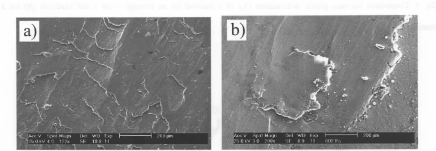
In the case of severe wear, tests led to a strong damage of the surfacewith material transfer from the sample to the ball. Plastic zones were noticed where the material is pushed leading to a wave type profile (see Fig. 5). After a sliding distance of 1600 m, the wear track depth evolved from 50 to 150 11mon the Al12Si coating (see Fig. 5.a) and from 20 to 70 11mon the Al 12Si- 14vol.%WC coating (see Fig. 5.b). SEM micrographies confirmed this point by
showing ahigh deformation of track (see Fig. 6.a).
a)
b)
fS21
'"Q
'"Q
:
:~tszl
". ,~ ~ ". .,. ". .. ~ - ,.. " .. .. .. . .. .. .. - ~ .. ~ ~ ~ " "-
, .. , .. "..""
...,.., u"".
. .., , .. ,,,...
,...,..Profil I Profil2 Profil 3 Profil4
Figure 5: Microtopographies and transverse sections of wear tracks after the 1600-m sliding test on: a) a coating performed from Al12Si, b) a coating performed from A112Si- 14vol.%WC(spherical particles).
SEM observations revealed also many wear scars. These may have a large size: up to 1 mm long and 0,5 mm wide. This delamination appears when the breaking stress is reached in the subsurface. The crack then growths to the surface forming a wear debris as shown in Fig. 6.b. This wear mechanism can be associated with "severe wear" as observed by Zhang and Alpas [17] during wear experiments on bulk aluminium-silicon alloys at high-applied loads. According to these authors, severe wear involves massive surface damage, high wear rate and large scale material
transfer to the counterface.
Figure 6: SEM micrographies of wear tracks after 1600 m sliding on a coating performed from AI12Si- l4vol.%WC
(spherical particles): a) plastic strain zones, b) delamination in progress.
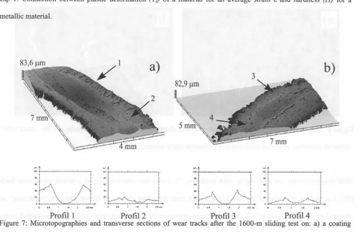
Mild wear is characterised by a regular track depth (Fig. 7), a wear rate reduction (Fig. 4), a homogeneous wear track (Fig. 8.a) and the formation of fme black debris. This type of damage gathers the characteristics of "mild wear" as observed by Zhang and Alpas [17] during wear experiments on bulk aluminium-silicon alloys at low-applied loads. For example, for the Al12Si- 44vol.%WC coating, the track depth was constant at around 30 ~m as shown in Fig 7.b. Moreover, the wear rate was significantly lower than the one observed with the lower carbide content: for Al l2Si- 35vol.%WC coating, it was 0,3.10-3mm3.m-lcompared with 2,5.10-3mm3.m-lin case of AlI2Si- 7vol.%WC coating or 4,0.10-3mm3.m-lin case of Al12Si coating. The wear rate was reduced by a factor ranging from 8 to 13. The same phenomenon was also noticed with the SiC- and TiC-reinforced coatings. The severe/mild transition can be explained as follows. Deuis et al. [18] showed that adhesive wear occurs when surfaces slide against each other and
the pressure between the contacting asperities is high enough to cause local plastic strain. The hardness of the surface
noted between the carbide content and the bulk hardness as shown in Fig. 3. As a result, this enhancement can explain the wear depth reduction as a function of reinforcement content (see Fig. 5 and 7) since the plastic deformation (YJ is linked to the hardness (H) according to the Eq. 1 [19]. A hardness increase causes therefore a plastic strain reduction, a wear depth reduction and a transition from severe wear to mild wear.
H=3Y
&Eq. I: Connection between plastic deformation (YJ of a material for an average strain E and hardness (H) for a metallic material.
a)
b)
_ELi
"0
'"Q
-0
'" .~ ,.. ... .. .. .. .. .. '" .. .. ., ., .. ., .. .. ., ..,, " . .. . u.. ,,..,,,, u.. ., .. , " , u.. ,, " . ..
Profil 1 Profil 2 Profil 3 Profil 4
Figure 7: Microtopographiesand transversesectionsof wear tracks after the 1600-mslidingtest on: a) a coating
performed from AI 12Si- 29vol.%WC (spherical particles), b) a coating performed from AI 12Si- 44vol.%WC
(spherical particles).
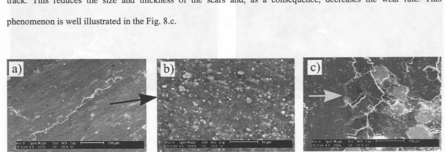
Mild wear is also characterised by the lack of strongly delaminated zones (Fig. 8.a). SEM observations only revealed some delaminations of fine sizes (10-100 !lm) and small depth (around 10 !lm) compared with severe wear. This small delamination can be explained by the plastic strain of the Al/Si matrix. In fact, during the sliding, the ductile Al/Si matrix is spread on the wear track, forming a tribolayer. The effect of the Hertz stresses caused subsurface fractures between this tribolayer and the reinforcement particles. Crack growth within the coating is limited by the
reinforcement particles under the tribolayer. These cracks grow up to the surface leading to the removal of the fractured fragments. Consequently, delamination mechanism only appears in the tribolayer that covered the wear track. This reduces the size and thickness of the scars and, as a consequence, decreases the wear rate. This phenomenon is well illustrated in the Fig. 8.c.
Figure 8: SEM micrographies of wear tracks after 1600 m sliding on a coating performed from Al12Si- 29vol.%WC (spherical particles).
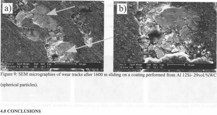
At high magnitude, the track surface of mild wear was composed of encrusted carbide debris (size ranging from 0,1 to 2 flm), as shown in Fig. 8.b. EDS analysis of this tribolayer showed also a high quantity of oxygen (around 20 at.%) compared with the as-deposited coating (oxygen content lower than 1 at.%). These EDS measurements were carried out on several coatings and wear zones. This may indicate that a certain volume of Ah03 was precipitated during the sliding and an oxidation wear was possibly established. Like carbide debris, Ah03 oxide has high mechanical properties and high wear resistance [18]. The simultaneous presence of carbide debris and Ah03 precipitates contributes to the protective properties of the tribolayer and the wear rate decrease. On the other hand, tribolayer effects were limited during severe wear. High plastic deformations and large debris delaminations contributed to the tribolayer disappearance. At a high reinforcement ratio (> 35 vol.%), SEM observations revealed the fracture of many carbides as shown on the Fig 9.a. These fragile particles were fractured by the ball impacts. This lead to the formation offine debris and to the protective tribolayer (Fig 8.b). However, the ball can embed a carbide debris oflarge size in a reinforcement carbide, leading to an important failure (see Fig 9.b). All these phenomena can explain the wear rate increase for coatings containing a reinforcement ratio higher than 35 vol.% (Fig. 4). As carbides have a density much higher than the Al/Si matrix (see Table 1), their failure increases quickly the mass loss and
(spherical particles).
Figure 9: SEM micrographies of wear tracks after 1600 m sliding on a coating performed from A112Si- 29vol.%WC
4.0 CONCLUSIONS
1. Al-based MMC laser cladding on Al substrate was successfully carried out using a Nd:YAG laser and a coaxial
powder injection system. Composite coatings were made of an Al/Si matrix (12 wt.% Si content) and reinforcements ofWC (spherical or crushed), TiC or SiC powders (volume fraction ranging form 0 to 50 %). 11. Coatings were free of pores or cracks and very well bonded to the substrate. Carbides were uniformly distributed
in the surface and appeared unaffected by the treatment, except for SiC adding.
111. Carbide reinforcement increased the bulk coating hardness up to a maximum value of 280 HV 5 regardless of the
AI/Si matrix.
reinforcement nature. This can be mainly explained by the shielding effect between reinforcement particles and
IV. As the volume fraction of TiC, WC or SiC increases, damage evolved from a severe to a mild wear and the worn volume was reduced by a 20 factor. Combination of three phenomena can explain this improvement: the decrease of surface deformation, the tribolayer formation and the lack of delamination.
v. Regardless of the reinforcement particle type, the higher wear resistances were observed with reinforcement
ratios of around 35 vol. %. The carbide nature did not seem to have a great influence, neither its shape. Although
the mechanical characteristics of the different reinforcement particles are dissimilar, no significant difference
5.0 REFERENCES
[1]: Y. Li, H. Yang, X. Lin, W. Huang, J. Li and Y. Zhou, Material Science Engineering A, vol. 360, n° 1-2 (2003) 18-25.
[2]: 1. Lin and W. M. Steen, Journal of Laser Applications, vol.10, n02 (1998) 55-63.
[3]: D. K. Das, K. S. Prasad and A G. Paradkar, Material Science Engineering A, vol. 174 (1994) 75-84. [4]: W. J. Tomlinson and AS. Bransden, Journal of Material Science Letters 13 (1994) 1086-1088. [5]: L. Dubourg, H. Pelletier, D. Vaissiere, F. Hlawka and A Cornet, Wear 253 (2002) 1077-1085. [6]: Y. Y. Qui, A Almeida and R.Vilar, Material Science Engineering A, vol. 33 (1998) 2639-2651. [7]: Y. Y. Qui, A. Almeida and R.Vilar, Scripta Metallurgica et Materialia, vol. 33, n06 (1995) 863-870. [8]: Y. T. Pei and J. Th. M. De Hosson, Acta Materialia (2000) 2671-2624.
[9]: T. Lietchi and E. Blank, Surface modification technologies VIII, Ed T.S.Sudarshan, TMS pub (1995) 421-427. [10]: J.M. Pelletier, P. Sallamand and B. Criqui, Journal de Physique IV, vol. 4 (1994) 93-96.
[11]: P. Tassot, Revue de metallurgie, 1 (1988) 81.
[12]: M. F. Ashby, Journal de Physique IV, Vol. 3 (1993) 1595-1600.
[13]: W. J. Tomlinson, J. R. McAra and AS. Bransden, Surface Engineering, vol. 6, n06, (1990) 213-218. [14]: J. A Vreeling, V. Ocelik and J. Th. M. De Hosson, Scripta Materialia, vol. 42 (2000) 589-595. [15]: J. Phillibert, A Vignes, Y. Brechet and P. Combrade, Metallurgie, Editions Masson, Paris (1998).
[16]: L. Lagrange, Caracterisation microstructurale et tribologique de revetements MMC elabores sous faisceau laser, PhD Thesis, University of Nancy, France (1997).
[17]: J. Zhang and AT. Alpas, Acta Materialia, vol. 2, n02 (1997) 513-528.
[18]: R. L. Deuis, C. Subramanian and J. M. Yellup, Computer Science Technologies, vol. 57 (1997) 415-435. [19]: A Cornet and J. P. Deville, Physique et Ingenierie des Surfaces, EDP Sciences, Paris, ISBN 2-86883-352-7 (1998) 102
![Table 1: Characteristics and mechanical properties of used materials [11].](https://thumb-eu.123doks.com/thumbv2/123doknet/14191479.478147/5.918.122.819.133.304/table-characteristics-mechanical-properties-used-materials.webp)