READ THESE TERMS AND CONDITIONS CAREFULLY BEFORE USING THIS WEBSITE. https://nrc-publications.canada.ca/eng/copyright
Vous avez des questions? Nous pouvons vous aider. Pour communiquer directement avec un auteur, consultez la
première page de la revue dans laquelle son article a été publié afin de trouver ses coordonnées. Si vous n’arrivez pas à les repérer, communiquez avec nous à [email protected].
Questions? Contact the NRC Publications Archive team at
[email protected]. If you wish to email the authors directly, please see the first page of the publication for their contact information.
NRC Publications Archive
Archives des publications du CNRC
This publication could be one of several versions: author’s original, accepted manuscript or the publisher’s version. / La version de cette publication peut être l’une des suivantes : la version prépublication de l’auteur, la version acceptée du manuscrit ou la version de l’éditeur.
Access and use of this website and the material on it are subject to the Terms and Conditions set forth at Errors when using façade measurements of incident aircraft noise
Bradley, J. S.; Chu, W. T.
https://publications-cnrc.canada.ca/fra/droits
L’accès à ce site Web et l’utilisation de son contenu sont assujettis aux conditions présentées dans le site
LISEZ CES CONDITIONS ATTENTIVEMENT AVANT D’UTILISER CE SITE WEB.
NRC Publications Record / Notice d'Archives des publications de CNRC:
https://nrc-publications.canada.ca/eng/view/object/?id=8065ec2b-9231-429c-8a29-bbc37909a3e4 https://publications-cnrc.canada.ca/fra/voir/objet/?id=8065ec2b-9231-429c-8a29-bbc37909a3e4
Errors when using façade measurements of incident aircraft noise
Bradley, J.S.; Chu, W.T.
NRCC-45384
A version of this document is published in / Une version de ce document se trouve dans : Inter-Noise 2002, Dearborn, Michigan, August 19-21, 2002, pp. 1-8
The 2002 International Congress and Exposition on Noise Control Engineering Dearborn, MI, USA. August 19-21, 2002
Errors When Using Façade Measurements of Incident
Aircraft Noise
J.S. Bradley and W.T. Chu
National Research Council, Montreal Rd., Ottawa, Canada, K1A 0R6
Abstract
This paper considers the problem of measuring incident aircraft noise when validating predictions of indoor aircraft noise levels from free-field outdoor levels such as those obtained from airport noise level contours. Both ASTM E966 and ISO 140/V indicate that the incident outdoor noise for measurements of the sound insulation of building facades can be obtained using microphones positioned at the building façade. Measurements of the incident aircraft noise at the façade and in the free field indicate that this can lead to large differences from simple expectations. This paper presents the results of measurements of aircraft passbys showing the variations in the incident sound levels as a function of the aircraft elevation. These were related to the effects of diffraction from the building façade as well as to the effects of ground reflections. This interpretation was confirmed both mathematically and using a scale model façade in an anechoic room. It was concluded that more general and easier to interpret estimates of incident sound levels can be obtained from free field measurements than from façade-mounted microphone measurements.
1. Introduction
ASTM E966 [1] and ISO 140/V [2] describe recommended procedures for measuring the sound insulation of building facades exposed to external noise. Although it may seem most ideal to measure the incident sound energy in the free field (i.e. away from reflecting surfaces), ISO 140/V does not recommend this approach and both standards permit other procedures for measuring the incident sound energy. These include façade-mounted microphones and microphones located 2 m from the façade surface. In ASTM E966 it is suggested that incident sound levels measured at the façade-mounted microphone will be 6 dB greater than those measured at a free-field position such as on a tall mast due to simple pressure doubling at a reflecting surface. At a position 2 m from the façade, coherent effects are expected to average out and an approximate 3 dB energy doubling is expected relative to a free-field measurement. However, when the sound source is aircraft noise, both standards suggest that the situation is more complex. ISO 140/V states that the results of global façade insulation measurements to aircraft noise cannot be compared with equivalent laboratory results. ASTM E966 suggests that the wide range of possible vertical angles will lead to
problems and accurate estimates of transmission loss are not possible using aircraft noise as the source.
Measurements in a large study of sound insulation to aircraft noise [3] included comparisons of measured incident sound levels for a test house at Ottawa airport as well as for new homes near Toronto airport. The ultimate goal of the work was to predict indoor sound levels from free field values of outdoor aircraft noise levels such as those obtained from airport noise contour calculations. The systematic series of measurements was intended to validate these predictions. This paper explores some measurement problems in attempting to accurately measure incident aircraft noise levels for these predictions.
The measurement results indicate very complex effects occur at the non-free-field locations and suggest these locations are not ideal for obtaining accurate measures of the incident aircraft noise. The results were confirmed using measurements on a scale model façade in an anechoic room and are explained as due to the combination of ground reflection and diffraction effects.
2. Measurements for Houses Exposed to Aircraft Noise
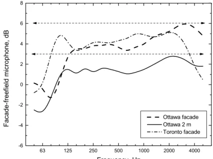
Measurements of the sound insulation of a small wood-frame test house at Ottawa airport [4] and of new houses near Toronto airport included both free-field and façade-mounted microphones to measure the incident sound energy. In some cases the incident sound at the Ottawa airport test house was also measured at a position 2 m from the building façade. The differences between the free-field results (obtained for a microphone 8.5 m above ground level) and the façade microphone results were expected to indicate an approximate 6 dB difference. Similarly the difference between free-field levels and those 2 m from the building façade were expected to approximate 3 dB. The average results of a number of aircraft flybys shown in Figure 1 indicate significant differences from these expectations.63 125 250 500 1000 2000 4000 -6 -4 -2 0 2 4 6 8 Ottawa facade Ottawa 2 m Toronto facade Facade-fr ee fi eld micr ophon e, dB Frequency, Hz
Figure 1. Average differences between the façade or the 2m positions re. free-field results. The two average façade-microphone results in Figure 1 are similar at mid-frequencies. At higher frequencies there are differences that may be influenced by the different facade materials (vinyl siding in Ottawa and brick in Toronto). The low frequency differences will
be related to the different heights of the façade microphones above ground level (1.65 m Ottawa and 2.1 m Toronto).
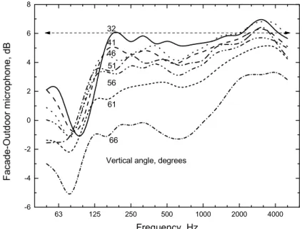
The large number of recordings at the Ottawa site were analysed in more detail to further explore the cause of the differences. Figure 2 shows measured differences between façade-microphone and free-field results for 23 different flybys by F28 aircraft. These were averaged in groups according to the measured vertical angle of the aircraft when it passed the test house. There are clearly large variations with frequency and with the vertical angle of the aircraft. Results seem to approach the simple +6 dB expectation for higher frequencies and lower vertical angles of the aircraft source.
63 125 250 500 1000 2000 4000 -6 -4 -2 0 2 4 6 8
Vertical angle, degrees 66 61 56 51 46 41 Facade-O u td oor micr ophone, dB Frequency, Hz
Figure 2. Measured façade effect for F28 aircraft vertical angle groups.
63 125 250 500 1000 2000 4000 -6 -4 -2 0 2 4 6 8 32
Vertical angle, degrees 66 61 56 51 46 41 F a cade -O ut door m icr opho ne, dB Frequency, Hz
Figure 3. Measured façade effect by vertical angle groups averaged over aircraft type. To determine whether the results in Figure 2 were related to the particular characteristics of the F28 aircraft, this analysis was repeated for results averaged over 81 events for 9 commercial jet aircraft types. These results shown in Figure 3, show a quite similar trend to
those in Figure 2 and again indicate large variations with frequency and the vertical angle of the aircraft.
The differences between the measured façade effects and the simple expectation of a +6 dB difference are thought to be due to a combination of ground reflection effects and diffraction effects. These will be explored separately in the following sections.
3. Ground reflection effects
The façade effect measurements are first complicated because the incident sound is the combination of a direct sound component and a ground-reflected sound component. These components combine at a measurement point to form a complex interference pattern that varies with frequency and with time as the aircraft passes the measurement point. The combined pressure at a microphone above the ground surface can be calculated as follows,
[
− + = 1 1 ( r d)2π /λ r d r r COS r r P]
(1)where, rd is the direct path length, m, and
rr is the ground-reflected path length, m
λ is the wavelength, m
The total effect of ground reflections over a complete passby was calculated by moving a source in steps along a flight track and summing the energy of the combined pressure values given by equation (1) at the receiver position. This was done for each 1/3 octave centre frequency and these sums were compared to similar sums for an equidistant direct sound only case. The model was further improved by adding an estimate of typical aircraft directionality [3] and of the effective reflection coefficient of the ground determined from published values of the acoustical impedance of a ground surface [5].
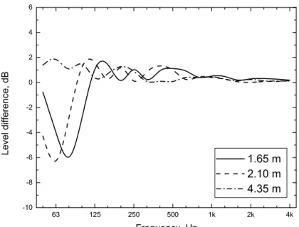
Figures 4 and 5 show some of the results of these calculations in terms of differences in levels integrated over complete simulated aircraft passbys. Both sets of results are for the case where the flight track is 240 m from the receiver as occurred for the measurements at Ottawa airport. The expected influence of receiver height above the ground is shown in Figure 4 for receiver heights of, 1.65 m (corresponding to the façade microphone at the Ottawa test house), 2.1 m (corresponding to the height of the façade microphone at the Toronto house) and 4.35 m (corresponding to a typical second floor room). There is a dominant low frequency dip that varies with frequency similar to the actual measurement results shown in Figure 1. The results in Figure 5 also show that the frequency of this low frequency dip is expected to vary with the vertical angle of the source. Again this is similar to the measurement results shown in Figures 2 and 3.
These calculations seem to explain the cause of the large low-frequency dip in the measurement results in Figures 1-3 as being due to destructive interference of direct and ground reflected sound from the aircraft. The results in Figure 4 suggest that this unwanted effect could be minimized by avoiding ground floor measurements where receivers are located relatively close to the ground.
63 125 250 500 1k 2k 4k -10 -8 -6 -4 -2 0 2 4 6 1.65 m 2.10 m 4.35 m Lev el differ enc e, dB Frequency, Hz
Figure 4. Calculated effect of ground reflections for varied receiver height.
63 125 250 500 1k 2k 4k -10 -8 -6 -4 -2 0 2 4 6 35 degrees 45 degrees 55 degrees 65 degrees Lev el differ enc e, dB Frequency, Hz
Figure 5. Calculated effect of ground reflections for varied vertical angle of the source.
4. Diffraction effects
To study the influence of diffraction effects on façade-microphone results and how these might vary with the angles of the incident sound, measurements were made on a model façade in an anechoic room. The model façade was ¼ scale of the actual façade of the test house at Ottawa airport. It was a plain sheet of 1.6 cm (5/8 inch) thick Melamine covered particle board. No attempts were made to model the details of the house which the façade was part of nor the effect of the ground in this study. Thus possible effects of the roof overhang and ground reflections were ignored. Measurements were made using an omni-directional sound source and with a microphone located at the center of the model façade and flush with its surface. The omni-directional sound source was moved by the measurement microphone along a straight line in steps simulating a passing aircraft. This was repeated for several
vertical angles of incidence. The diffraction effects are described in terms of the ratio |p/po|,
where p is the measured pressure at the centre of the façade and po is the measured pressure at
the same distance without a façade present.
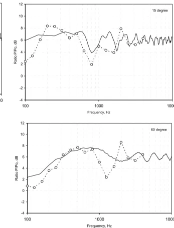
Figure 6. Comparison of measured (solid line) and computed (dashed line and circles) diffraction effects versus frequency and by vertical angle of the source for the model façade.
0 degree -4 -2 0 2 4 6 8 10 12 100 1000 10000 Frequency, Hz Ra tio P/Po , d B 45 degree -4 -2 0 2 4 6 8 10 12 100 1000 10000 Frequency, Hz Rati o P/Po, dB 15 degree -4 -2 0 2 4 6 8 10 12 100 1000 10000 Frequency, Hz R a ti o P/ Po, dB 60 degree -4 -2 0 2 4 6 8 10 12 100 1000 1000 Frequency, Hz Ratio P/Po, dB
For a simple verification of the experimental procedure, results obtained for the different vertical angles of the sound source in the plane perpendicular to the façade were compared with computed values using the approximate diffraction theory of Wiener [6]. Comparisons were first made for the more ideal cases of a square and a circular model façade. These showed good agreement between scale model measurements and calculated results. Reasonable agreement was also obtained between experimental and computed results for the ¼ scale model of the actual house façade as shown in Figure 6. These results compare calculated results with scale model data for four different vertical angles: 0, 15, 45 and 60 degrees. Both measurements and calculations show that significant variations in levels at the façade microphone occur due to diffraction effects.
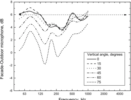
Figure 7 shows scale model measurements of the diffraction effects for a more extensive range of vertical angles of the source and for averages over the complete simulated passby of the source. Because it was a ¼ scale model, measurements were made at 4 times the scale frequencies. However, in Figure 7 results are plotted in terms of the equivalent full-scale frequencies to allow easy comparisons with the results obtained at the test house in Figures 2 and 3. It was not possible to include results at higher frequencies because the measurement microphone was not capable of correctly recording the higher frequencies used in the model measurements.
The results in Figure 7 for the model façade again show complex variations with frequency that also vary with the vertical angle of the sound source and tend to approach the simple +6 dB expectation for normal incidence of the passing sound source. That is, when the source is in the horizontal plane. These results indicate that diffraction effects could cause errors of up to 8 dB from the expectation of a +6 dB pressure doubling at the façade microphone. They tend to approach the simple +6 dB expectation for vertical angles approaching normal incidence of the passing sound source.
The scale model measurements and calculations both represent a simpler situation than the real building façade in at least two important features. The models do not include a ground surface nor a roof overhang as were present for the measurements at the test house. Therefore the low frequency interference dip in the Figure 2 and 3 results, due to ground reflections, is not present in these diffraction results. The diffraction effects for the real house would also be different because the model was a simple rectangular panel in a fee field with no adjacent surfaces. The façade of the Ottawa airport test house was connected to the ground at the bottom and partly shielded by an overhanging roof at the top. Thus one would not expect the details of Figure 7 to match those of Figure 2. However, the results do show a similar magnitude of fluctuations and a similar departure from the +6 dB expectation as the vertical angle increases. 63 125 250 500 1000 2000 4000 -6 -4 -2 0 2 4 6 8
Vertical angle, degrees 0 15 30 45 60 75 F a cade -O ut door m icr opho ne, dB Frequency, Hz
Figure 7 Measured diffraction effect for a ¼ scale model façade for varied vertical angle. (plotted versus full scale frequencies).
The total measured effects at the test house would be expected to be a combination of the ground interference effects in Section 2 and the diffraction effects illustrated here. Since the calculated diffraction effects do not include the full details of the façade of the test house, no attempt was made to combine the expected effects of ground reflections and diffraction.
5. Conclusions
The problems of predicting indoor aircraft noise levels from free field outdoor levels such as those indicated by calculated airport noise contours is complicated by ground reflections and diffraction effects.
The assumption, that the difference between measurements of incident aircraft noise at façade-mounted microphones and free-field microphone positions is a simple +6 dB correction, will lead to large errors in estimating incident sound levels. Similarly, measured incident sound levels at positions 2 m from the façade are not always 3 dB greater than free-field measurements. Large differences from these simple expectations occur and vary in a complex manner with frequency and the vertical angle of the source. Errors of up to 12 dB were measured at important low frequencies for actual aircraft flybys.
Measurements at positions 2 m from the façade would be less affected by diffraction effects but would still include large effects of ground reflections. Façade mounted microphones at
2nd floor (or higher) locations would avoid the major effects of ground reflections but would
still include significant diffraction effects. These effects may be different for road and rail noise sources because of the different vertical angles of incidence.
Relatively simple estimates of the effects of ground reflections are possible. However, it seems impractical to attempt to produce accurate corrections to account for the combined effects of ground reflections and diffraction effects as a function of the particular source position at façade-microphone positions. Averaging over multiple façade microphone positions as suggested in the standards [1,2] may help but a complete understanding of the effects of diffraction on the transmitted sound energy are not available. In addition, the details of the façade surface properties and the mounting of the façade microphone can also influence façade microphone measurements. It was therefore decided that for our field sound insulation tests, the incident aircraft noise would be measured at free-field microphone positions remote from reflecting surfaces to give more generally representative numbers.
Acknowledgements
The project was jointly funded by the National Research Council, Transport Canada, and the Department of National Defence with further support from Vancouver International Airport.
References
1. Anon, ASTM E966-99, “Standard Guide for Field Measurement of Airborne Sound Insulation of Building Facades and Facade Elements”, Am. Soc. for Testing and Materials, Philadelphia.
2. Anon, ISO 140/V-1998, “Laboratory Measurement of Airborne Sound Insulation of Building Elements – Part V, Field Measurements of Airborne Sound Insulation of Façade Elements and Facades”.
3. J.S. Bradley and J.A. Birta, “Laboratory Measurements of the Sound Insulation”, IRC Internal Report, IR-818, October 2000.
4. J.S. Bradley, “Comparison of Laboratory and Field Measurements of the Sound Insulation of a Wood Frame Home”, Proceedings of Inter Noise 2002, paper N404, Dearborn, August 2002.
5. M.J. Crocker (ed.), “Encyclopedia of Acoustics, Vol. 1, p. 347, John Wiley, New York (1997).
6. F.M. Wiener, “The Diffraction of Sound by Rigid Diskes and Rigid Square Plates”, J. Acous. Soc. Am. 21, 4 (1949).