Symeon Gerasimidis
Diploma Civil EngineeringAristotle University of Thessaloniki (2005)
Submitted to the Department of Civil and Environmental Engineering
In Partial Fulfillment of the Requirements for the Degree of
Master of Engineering in Civil and Environmental Engineering
at theThe author hereby grants to MIT permission to reproduce and to
distribute publicly paper and electronic copies of this thesis document in whole or in part in any medium now known or hereafter created.
Massachusetts Institute of Technology
June 2006O
2006 Syrneon Gerasimidis All rights reservedSignature of Author May 23,2006 A
wms
,NSM-' OF TECHNOLaGYpi'izq
LIBRARIES
...
...
Certified by ! Z .:.: .:. ...
b..I f - Professor o Civil and Environmental Engineering
/
Jerome J. Connor Thesis SupervisorAccepted by
...
.=...
%-....
-. . *.- ... Andrew Whittle Chairman, Departmental Committee for Graduate StudentsSymeon Gerasimidis
Submitted to the Department of Civil and Environmental Engineering
on May 23,2006 in Partial Fulfillment of the
Requirements for the Degree of Master of Engineering Civil and Environmental Engineering
Abstract
The need and ambition of humanity to go higher and higher is something that is amplified as time evolves. It is the same need that leads engineers to push their structures to higher limits.
However, when engineers design higher structures their knowledge and their abilities are challenged. In that sense, during the design process of a high-rise building all the strange phenomenon of the behavior of the structure must be considered.
A very significant factor that affects the limits of today's high-rise construction is the wind loading. Bracing the building in a clever and more efficient way was always a difficult task for designers and engineers. This thesis deals with a bracing system called the knee-bracing system. The application of knee-bracing system for high-rise buildings is not yet fully determined and this study will try to describe the problem and provide some solutions. Knee-bracing will be checked and the possibility of providing the required results using the minimum amount of material and giving the maximum space for use from the residents or workers of the building will be examined.
Several different cases of loading and knee-bracing systems are considered and an optimization for the design of such systems is described. The last part of the document describes the idea of adaptive stiffness, something new for high-rise buildings. Reinforcing these ideas, solutions for the construction of these bracings are also provided.
I am deeply grateful to my s u p e ~ s o r Jerome J. Connor. For me, his advice on everything was always an invaluable guide for all my choices. I consider myself very fortunate having met and worked with a person like him. His example is always going to be a pharos for my life.
My family Thomas, Efi and Despina is one of the main reasons why I am in this place. Their upbringing makes me very confident and their support throughout my whole life gives me strength and courage to continue improving myself.
My friends and especially Dimitrios Iliadelis who was more like a brother to me during our year in MIT helped me go through a lot of difficult situations. Petros Englezos and Dimitrios Andritsos, my closests, have been an incredible, everyday support. I am sure and happy that this deep friendship will keep strengthening.
I am also very indebted to my friends from the program who made this year special. I will always look back upon my time at MIT with great memories with Jeremiah, George, Despina, Aurelie, Takis, Naeem, Alessia, Roberta, Violeta, Milan, Juan, Lauren, Ricardo, Adrian, Nick, Claire, Samar, Maria, Rosella, Sinan, Paul.
Table
of contents
1. Introduction 5
2. Stiffness problem 9
2.1. Bracing a 20 floor building
-
description of the building, geometry and l o a d i n ~ 92.2. The bracing system 15
2.3. Results 20
2.3.1. Displacements 21
2.3.2. Bending moments on the columns 24
2.3.3. Bending moments on the beams 29
2.4. Variable sizes of the diagonals 37
2.5. Optimizing the distribution of the diagonals 46
2.5.1. General 46
2.5.2. Different loads 48
2.5.3. Position of diagonals 50
2.5.4. Local change of stiffness 51
Adaptivity-active stiffngs 53 Constructability 57 Conclusions 59 References 60 List of figures 61 List of tables 64
1)
Introduction
The race towards new heights has not been without challenges. After the invention of the elevators by E.G. Otis and the use of structural steel as the material for the structure, skyscrapers have continued to go higher and higher where they started to face strange wind effects and very high wind loading. Unfortunately, these advances in height were often combined with increase in flexibility and lack of stiffness or damping, increasing their vulnerability to the actions of the wind.
Lateral loading was a loading condition that structural engineers considered relatively late. It was the damaging force of nature in the form of wind or earthquake that made the engineers think that the lateral load could indeed produce very significant problems in the structure. Therefore, the idea that permitted structural engineers to design high rise buildings was the bracing of the building with several different ways. The use of the stiffest geometrical form, which is the triangle, was the dominant idea. Triangular form can be integrated in the geometry of the building with infinite ways.
Figure 1 illustrates different schemes of integrating the triangular shape inside a square. - - - -
a) D-I
bracing \ K h d n g bracing X hmring
6)
0 1 2 3 4 5 6
Figure 1. Image from 'Parametenzed versus Generative representanons in smctural design : an empinkal comparion. "
The selection of each of the above shown geometries depends of course on the loading problem, the overall geometry, the desired result, the availability of the material and on several other reasons. All the above bracings, when used for wind loadings, are called wind bracings.
Wind bracing provides the lateral stability of the building. It consists of cross bracing located in roof and sidewalls, in one or more bays depending on the loadings and the height of the building.
Although the bracings shown above have been mostly used throughout the history of high rise buildings, they have a common disadvantage. There is no possibility of having openings in the square, therefore the option of having windows, doors or any kind of opening is not
-- -- -
feasible anymore. That is why engineers came up with a scheme of bracing, the so-called knee bracing.
Figure 2. Knee bracing
The knee bracing provides the same stiffness as all the above bracings, without having the disadvantage of blocking the space inside the square of beams and columns. As shown in figure 2, the only area that is blocked by the bracing elements is the area around the connection of columns and beams which is usually already hidden by false ceiling because of mechanological purposes.
The structural result is to stiffen significantly the column-beam connection whose flexibility usually produces the overall flexibility of the building. It must be noted that the result of the knee bracing depends on whether the column-beam connection is a moment connection or a braced connection.
Figure 3. Application ofknee bracing by Ceco Building Systems. Image taken from Ceco website
According to their website:
cciUWE
BRA
CING: This system consists of a knee brace and beam armogement which, when connected to Pn'mary Fmme columns, provides economical bracing to resist moderate eave hrces. 72e diagonal knee braces, llorated a t each end of the beam, consist of double aogle members which will intemect the column 4'0" below the beam member on buildings up to I4'0"eave hekht and 5'0" below on buildings w*th eave hexghtsgreater than I4'O9;The
beam
is an extm member added, parallel to the eave stlut, in knee braced bays. The number of knee braced bays prowdedin any side w d will be as required by design. 72e stlucturd design of the knee brace is based on the beam bahgpimed a t both ends, wirb rlie Primary Frame column designed h r weak axis bending.Koee Bmcing is designed to c a q the entire longituuCnal wiad/seism'c eave h e load ~ ~ ' t h o u t
sban'ng any of this land wWIth any other bracing system."
The application of Ceco deals with small buildings and low wind loads. The effect of the application of knee bracing in high-rise buildings still remains not widely applied. This thesis will try to investigate what are the effects of using knee bracing in high-rise buildings.
Chapter
2.
Stiffness
problem
2.1
Bracing on
a 20 floor
building -
description of
the building
Geometry
The material in this section demonstrates that small elements located close to the connections of beams and columns (knee bracing), provide adequate lateral stiffness for a high rise building structure. Based on the resulu of this analysis, the rest of the chapter focuses on how to distribute these diagonals throughout the height of the building to optimize their performance. A lot of factors were taken into account such as different sections for the diagonals, different loading conditions, different locations and others.
For the purpose of the analysis a 20 floor steel frame building was selected. The geometry of the building is shown in the following images.
A simple building was considered to be more appropriate for the analysis, since a complicated geometry would be comparatively intensive. The software used for all the analysis and simulation is SAP 2000. Furthermore, the effect on a 20-story building would provide insight on the behavior of taller buildings.
Figure 4. Front view of r6e modelin SAP
The plan view of the building is shown in figure 5.
5
Figure 5.
PIan
view of the modelin SAPThe building is a steel frame building which is supported by 4 comer columns which are box sections, a middle column which is also a box section and another 4 columns which are I sections. The cross section of the building is a square and this was selected in order to have symmetry in the two different wind directions. For that reason only one of the wind directions was analyzed and not both of them. The dimensions of the elements as shown in figure 5 result in an aspect of :
m
height
l
which is typical of non-slender buildings.
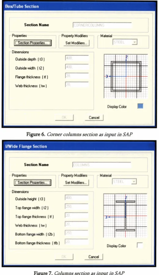
Some dimensions were input for the elements themselves. The beams are I sections. The dimensions of these sections, in millimeters are shown in the following figures:
Boxllube Section
Figure 6. Comer coIumm section as hput in SAP W i d e Flange Section
I
2- , ,,- -, ---F---+*9F ., .-
, < . w : . A 1;- .- ' : .P : .?! *cT'F . :I .I,. - ,
Figure 7 . C o h s section as input in SAP
1 C - J
Figure 8. Beams seerion as input in SAP
The sections of the columns were considered to be uniform throughout the height of the
building. In a more realistic case it is possible to have changes in the different heights of the building. Nevertheless, for a 20 story building, the use of uniform columns sections is considered to be realistic.
Loads
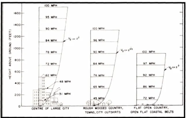
The critical loading that the structure will be evaluated for is the wind loading. Although there are a lot of different factors that affect the application of the load in a dynamic way, the load for this first analysis will be considered to be static. In case of a more time flexible schedule the effect of making the knee braces also working as dampers would be analyzed. It is proven that the wind load on a structure follows a pattern which can be shown in figure 9 below. However, for the purposes of this thesis a linear increase of the wind load throughout the height of the building was considered to be accurate enough.
Figure 9. Ideal wiod load dismibution. Image taken from http:/ivww.geocities. com/lpittac~cae6~4pro~ htm2
The wind load that was considered for the model is shown in figure 10 on the next page. This wind load is not scaled or calculated in detail, so using the load combination factor can be changed so that real values can be reached.
2.2
The bracing system
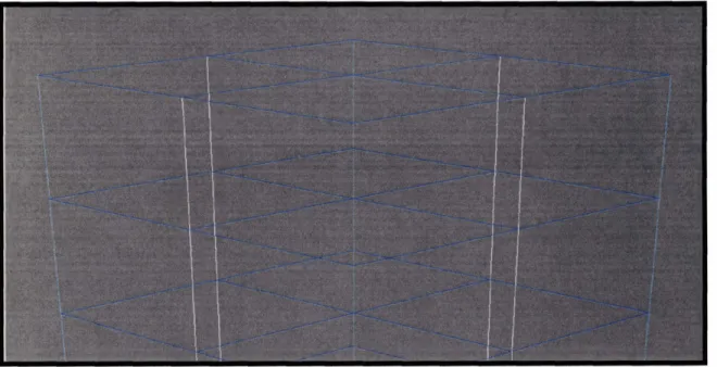
The bracing system that is going to be analyzed in this building does not consist of the usual big diagonal elements that would be connected from the base of a column to the head of the adjacent one or like any other bracing that is described in the introduction. The bracing system that was designed in the particular building consists of small diagonal braces that are connected close to the joints of columns and beams. The unbraced building is shown in the figure 12 below.
Figure 12. Unbraced buildnggeometly
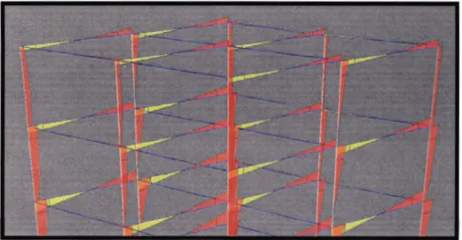
A wind load applied on this unbraced building produces the moment diagram, which governs the design of all the elements and mainly the columns and the beams, as shown in figure 13. The highest values appear close to the beam-column connection. Taking into account the fact that each element must be a uniform element the designer is forced to design each element with this very high value which appears at the two ends of the element. The rest of the element is not working with the same efficiency, since there is much more material than needed.
'L
Figure 13. Unbraced builchg moment of diagrams under h e a r wiod load
Applying the normal bracing solutions to this geometry to avoid this moment diagram with the diagonal bracing as shown in figure 14 does not change the shape at all.
Figure 14. Diagonally braced building
In figure 15, the moment diagram of the diagonally braced building is shown. It is obvious that the shape of the diagram is not at all lowers from the unbraced building. It is true though that the values of the moments in the plane, perpendicular to the loading are now much higher than the values in the longitudinal plane (parallel to the loading).
The The in a
bracing elements as a first approach were selected to be pipe sections shown dimensioning of the bracing elements and the distribution of their stiffbess later chapter.
figure 17. described
Figure 17. Bracing elements section charactenstics
These elements are connected to the beams and the columns, with pins. There is no moment transfer through the bracing elements. They only transfer axial loads.
Figure 18 shows the moment diagram of the knee-braced building. The first goal which was to reduce the maximum bending moments at the two ends of all the elements is now achieved since the bracing elements have the effect of changing the diagram in to a more uniform one.
The maximum moment value of the beam or column now appears at the point of the connection of the bracing element, a point which can be also easily locally reinforced with stiffeners. Thus, the governing design moment can be even more decreased.
2.3
Results
The main goals of any bracing system are to make the structure stiffer and to reduce moments and forces in the rest of the elements. What follows are the results showing this effect of the knee-bracing system on displacements and moments of the beams and columns.
2.3.1.
Displacements
A major function of the bracing system in any structure is to reduce the displacements of the structure. In a high-rise building in particular the displacements play a very important role since they can produce discomfort for the residents or workers that work at high floors. By inputting this bracing system the deflections at the top and centre of the building are decreased as shown in the table below:
Ratio: Displacementheight of the building
1
Knee- bracedI
201,13
I
1/300
I
Percentage decreasedI
27,2%
I
I
- - -Table 1. Displacements a t the top of the building of the unbraced and the knee-braced building
The percentage that the displacements are decreased is significant and it proves that the bracing system works indeed and it is crucial for bringing the displacements inside the allowable limits. The deformed shape of the main column is shown in the following diagram.
Figure 19. Deformed shpe of the centre column building
Figure 20. Percentage decrease of the displacements w'th the he~ght of the building
It is obvious that the centre column of the building behaves as a fixed cantilever.
In figure 20 the percentage of the decrease for the displacements is presented. It can be noted that the effect of the bracing starts at the fourth floor approximately where the percentage decrease of the displacement is around 25%.
In addition one can see that the percentage above the seventh floor remains constant around
26-27% although the loading is still rising. A first conclusion that one can draw from this graph is that the knee-bracing elements affect the displacements in a uniform way. The effects of the knee-bracing system in the lower floors are not so significant and maybe they
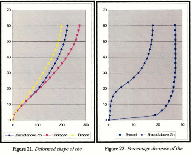
could be avoided. For the lower floors, say below the seventh floor figures 21 and 22
compare deformed shapes for the braced and partially braced cases.
Figure 21. Deformed shape of the centre column building
Figure 22. Percentage decrease of the displacements w*th the height of the building
This transition part for the half braced building is longer now and it covers approximately from the 4th floor (12m) to the 17& (51m), in total 39m, while for the fully braced building this part is only 4 floors = 12m.
A second conclusion that comes out of these graphs is that bracing the building horn the ground floor is something that provides extra stiffness to the building which is not negligible since it permits the bracing to start working at a lower height and decreases the displacements all along the building.
- -- - -- - - - -
2.3.2.
Bending
moments on the columns
One very important characteristic of a high-rise building that affects the design and cost, is the bending moment values and diagram of the columns. It is usual that a lot of details depend on the section and the dimensions of the columns section. So, in addition to the main load carried by the column which is the axial load, the bending moments due to lateral loads such as wind or earthquake play a very important role in the overall design of the building. In order to get a good perspective of the nature of the bending moment diagram for the columns of the building under the applied wind load, the centre column was considered. Figures 23 and 24 show the bending moment diagrams for that column corresponding to the unbraced and the braced condition.
This can be easily noticed through a closer look at the base part of the columns which is shown in figures 25 and 26. It is obvious that there is a change between the two cases which
creates a more uniform and more efficient diagram for the braced condition. The strength of the column can be better used in the braced case while in the unbraced condition the column is designed for the maximum value which appears only at the end of the column.
r lgure u. om&g moments of the unbraced buildhg
Figure iu. bend'& momeua of the braced building
In more detail the difference between the two bending moment values is shown in table 2 which follows on the next page.
- -
Table 2. Bending column moment values for the braced and the unbraced case and the percenrile difference
One can notice that the decrease in the moment values follows again a uniform pattern above the seventh floor. This can be noticed easily in figure 27 (next page). Until that there is a part that the percentage decrease is increasing until reaching the average value, which is around 20%.
Figure 27. Percentile column moment values decrease as a function of height
According to the code then, having reduced the applied moment by 20% and calculating the
wpi for the column:
One can see that there is a 20% decrease in the required wpi of the column. This can be
translated in weight as shown in the following table.
I
section (wpl in Weight of section (kgdm)=
Unbrac building
2.548.000
I
Knee- braced building
2.038.400
135,O
Percentile decrease
20%
8%
Table 3. We~ghr decrease of the column
The effect of knee-bracing on the columns is significant since they can be reduced as much
as 8% from their initial weight. This means an immediate decrease in the dimensions of the
2.3.3. Bending moments on the beams
One main factor that affects the total behaviour of the structure is how the beams are connected to the columns. The two different ways in which this connection is realised are:
1. Moment bearing connection = Moment Frames 2. Pin connection = Braced frames
So far, all the analysis that has been done and presented incorporated moment frame
connections for the beams. This does not mean that this is the only way though. In this
chapter the braced frames will be analysed and the comparison between moment and braced frames will be presented.
1. MOMENT FRAMES
In case of wind load applies on the structure, the shape of the bending moment diagram for the beams and for the braced and unbraced structure is like the one shown in figures 28 and 29 below.
Figure 28. Beam moment diagmm for the unbraced building
One can notice once again the triangular shape of the diagram, which means as mentioned that there is not very high efficiency in the design process for the beam, since the design is governed by the high end value of the diagram.
Figure 29. Beam moment diagram for the braced building
Bracing the building immediately changes the shape of the moment diagram for the beams. It creates a more uniform shape having the maximum value in the connection of the bracing
element with the beam. The values of the moments for the two conditions and the percentile difference can be shown in table 4 below.
Table 4. Bending
beam
moment values hr the braced and the unbraced case and the percentile dfferenceThese values are plotted as a function of the height of the building in figure 30. It is noticed that the same pattern appears. Below 21m (seventh floor) there is the transition part of the building where the percentile decrease of the moments is increasing until reaching the average value of decrease, which is 27%.
Figure 30. Percentile beam moment values decrease as a finction ofheight
Applying the code again, having reduced the applied moment by 27% and calculating the wpl for the column:
One can see that there is a 27% decrease in the required wpi of the column. This can be
translated in weight as shown in the following table.
Necessary section (wpl in Weight of section (tonslm) mm3)
Unbraced building
F%iE
45,5Knee- braced building
460.630
40,4
Percentile decrease
I
27%
I
1
1,29/0
I
Table 5. Weight decrease of the beamThe effect of knee-bracing on the beams proves to be more significant than the columns since they can be reduced as much as 11,2% from their initial weight. This means an immediate decrease in the dimensions of the column which can provide even more space for the working area of the building.
Table 6 contains a summary of the two decreases in weight (columns and beams), along with the increase in the total weight of the structure by inputting the bracing elements.
I
ColumnsI
BeamsI
Bracing elements7
Total weight of the unbraced elements (other
columns and comer
135,02/238,64
columns, in m)Percentile
8%
1
1,296
-
decreaselincrease (%) Total length of elements
(other columns and comer
240+300
1440
226,416
columns, in m)
Absolute weights (tons)
104
65,6
Absolute decrease/increase
8,32
7,3
20,1
Total weight of the braced
elements (kgr/m)
95,68
58,3
20,l
Table 6. Calculation of the weight of all elements of the structure From the above we have a total increase in the weight of the structure of about:
This means that not only the building is stiffer and the displacements are limited, but also the total weight of the building is increased by a very small number. As a percentage the increase of the weight of the building is:
This
means that there is a increase of approximately 2,6% of the total weight of the steel structure.2.
BRACED
FRAMESAnother way to connect beams and columns is with pin connections. This way is preferred since these connections are much easier to be constructed than moment frame connections. However, the overall stiffness of such a building is none (unbraced).
The first approach to the braced kame problem was simply to input the kame releases at the ends of all the beams and run the analysis keeping all the rest of the characteristics of the sections and the geometry the same. However, when this analysis run, the results for the unbraced "braced" frame were extremely out of the normal spectrum because this building is a mechanism. When the same geometry including the bracing run, the results were logical. It has to be noted here that a frame building with pin connections at the end of its beams is an unstable building. That is why when putting knee-bracing the building becomes incredibly stiffer than before. Something that proves that bracing is much more important in braced frames.
However, in order to start with good results the sections of the elements of the structure were changed. All the above are summarized in table 7 below.
Unbraced (moment frame)
276,34
I
-
I
Knee-braced (moment frame)
I
201,13
I
27%
I
Unbraced (braced frame-
Several
meters
(&Jm)
same geometry)Knee- braced (braced frame) - -
I
207,26
I
Very
high
I
Unbraced (braced
changed geometry)
frame-
I
Knee-braced (braced frame-
80
98%
changed geometry)
Table 7 . Displacements at the top of the buildng for the unbraced and the knee-braced building (moment aad braced fiarne)
close to the moment frame building. Something that leads us to the conclusion that in case a knee-bracing system is used a simply braced frame system must be preferred and there is no need for moment bearing connections between the beam and the column.
Regarding the moment diagram for the beams, the effect of knee-bracing is again much beneficial. In figures 31 and 32 the beam moment diagrams are shown for the unbraced and the braced "simply braced building".
m
Figure 31. Beam bending moments for the unbraced C'simply braced" building
r
Figure 32. Beam bending moments for the braced '$imply braced" building
It
must
be noted here though
that the maximum values of the
moments
for the
beams
are
much
lower for
the
unbraced condition. This happens
because
the
beams
in
the unbraced condition do
not
take
part
in
the
structural system
of
the
building
that
reacts to the wind load.
On
the other
hand,
when
braced, they
become a part
of
the structure
that
actively plays a role bearing
lateral
loads.
That is why the diagram for the unbraced condition is a parabola. It is only because of the dead loads, there is no moment transfer in the ends of the beam. In the braced case there is moment transfer because of the bracing elements.
Variable sizes of the diagonals
A very important factor when designing the knee-bracing system is the section of the diagonal bracing elements. For the purpose of the analysis a pipe section was used initially as
described in previous chapters. However, the dimensions and characteristics of the section is something so far not defined and at the same time is something that can change a lot the
behaviour of the bracing system. For that reasons several different sections were used and
the structure was analysed after each change. According to the results and the best behaviour of the system, the optimized section will be selected in the end of the chapter. In table 8
below all the different sections are presented:
Table 8. DMerent sections of diagonah checked Analysis #1 Analysis #2 Analysis #3 Analysis #4 Analysis #5 Analysis #6 Analysis #7 Analysis #8 Analysis #9 Analysis#lO Analysis # 1 1 Analysis #12 A
Three different diameters for the pipe section were selected and for each diameter four different thicknesses were also selected, in total 12 sections. After running the analysis for all these different cases the displacements at the top of the building were extracted. In figures 33 and 34 these displacements are shown in graphs firstly as groups of the same diameter and secondly as a function of the weight of the diagonals.
100110 100/12 100115 100/20 120/10 120/12 12011 5 120/20 150/10 150112 150/15 150/20 L
21 2 210 208 206 204 202 200 198 196 1 94 I I 1 1 2 3 4
+
Diameter 100 -m- Dameter 120 + Diameter 150 - -Figure 33. dip lace men^ at the top of the building asgroups for the same diameter From figure 33 one can notice that there is a logical decrease in the deflection of the building as the stiffness of the diagonal increases, either because of diameter increase or of thickness increase. On the other hand figure 34 shows a rather not uniform pattern of decreasing the
deflection with the increase in the weight of the diagonals, which means that the
optimization of the diagonal section does not only depend on the weight, thus the area of the section, but also on other characteristics such as the moments of inertia. Optimizing the section of the diagonal also must include the result that comes out of a change in the
diagonals. For instance a decrease of 5% in the deflection (from 210mm to 199,3mm) is
translated into an increase in the weight of the diagonals of as much as 30096. Increasing the weight of the diagonals 300% just for a minor decrease in the deflection is certainly not the most efficient way of doing it.
21 2 21 0 208 206 204 202 200 1 98 1 96 194
Table 9 below shows all the different sections and their characteristics.
Table 9. DMerent secaons and their charactenstics
Considering the fact that all the deflections are very close, compared to the initial not braced building, it is reasonable to try to compare the total increase in the tonnage of the structure due to the bracing. The heaviest diagonal used from the above table is the diagonal with a diameter of 150mm and a thickness of 20mm. The total increase in the structure's self weight is calculated and shown in table 10 below. It has to be noted that the self weight of the building without any bracing is around 167,37tons.:
Weight (kgr) - 20,939095 17 24,56853833 29,6637 1816 37,22505808 25,59222743 30,15229704 36,64341655 46,5313226 32,57192582 38,5279351 1 47,1129641 3 60,49071938 Diagonals Deflection at the top (mm) Area (mm2) Length
(mm) lCrv/lO 10011 2 100115 100120 120110 120112 120115 120120 150110 150112 150115 150120
Table 10. Total increase of self weight of the structure due to diagonal bracing (the worst
case)
Number of single diagonals
Number of double diagonals
Total number of diagonals Total weight of diagonals
Increase in the tonnage of the building
MASSACHUSETTS INSTITUTE OF TECHNOLOGY 39
210 207,9 205,62 203,22 207,4 205,4 203,4 201,23 204,6 202,9 201,13 199,3 200 40 280 16940kgr= 17tons 4 0 % 2827,433388 3317,521842 4005,530633 5026,548246 3455,75 1919 4071,504079 4948,008429 6283,185307 4398,229715 5202,477434 6361,725124 8168,140899 943,4 943,4 943,4 943,4 943,4 943,4 943,4 943,4 943,4 943,4 943,4 943,4
In table 10 there are two types of diagonals described. Single diagonals and double diagonals. This will be analysed in detail in chapter "adaptivity-active stiffness" but a note must be written here as well. The concept was to put double diagonals in places that could have the space and the possibility to do that. In figure 35 below, these diagonals are shown in a different colour. The only difference in the simulation of these diagonals was that they only
double the area of the section, so they can take double the axial force. The reason why these diagonals appear at that points is explained in chapter "adaptivity-active stiffness". In a more
detailed simulation two actual elements should be included in the model.
Figure 35. Places of the double diagonals
It is shown from table 10, that the maximum increase is about 10% of the self weight of the unbraced building. This number is considered to be very low, since the benefits of using these elements are very important and create a much stiffer structure than the unbraced one. Having all these results of sections with different diameters and different thicknesses was very helpful and gives a very good perspective of how the knee-bracing works, but at the same time creates some confusion. A better way of approaching the problem would be to change one of the two variables to a constant number so that it would be easier to understand the behaviour of these elements. So, in order to find out better and more reliable results, a further analysis was conducted. It was decided, considenhg also constructability constraints, that a reasonable diameter of the diagonals could be 200mm. Having this as a constant, different thicknesses were examined to see the comparison between the decrease in
compared to the one of the unbraced structure and the change in the period of the structure using all these different diagonals.
able
11. Difirent diagonah used WIUI h e same diGeter and resultsAs shown above, many different thicknesses were examined, starting from a very thin profile of 5mm and reaching a very thick one of 50mm. Figure 36 below shows the increasing weight of the diagonals.
Figure 36. Weight of diagonals
Projecting the results that appear in table 11, the following graphs came out. In figure 37 the deflections at the top of the building are shown as a function of the thickness of the diagonal bracing elements. It can be noticed that small changes in the thickness of the diagonals, when the thickness is still low, produce significant decreases in the deflection of the
building, while changes in the thickness of the diagonals in high thicknesses hardly affect the deflections of the building. It must be noted here that the decreasing tangent of the curve of figure 37 shows that the thicker the diagonal becomes the lea impact rate can have on the deflection of the building. That is why the optimum thickness that can be extracted from
that graph is around 20mm, since above that thickness there is much weight increase and less stiffness increase.
Figure 37. Deflections at the top of the bw'Idli3g as a function of the thickness of the diagonals
This can be also shown from the graph of figure 38 which show the same curve of figure 37
Figure 38. Deflections a t the top of the building and weight o f the diagonals as functions o f
the thickness o f the diagonals (all percentages)
An important characteristic of the structure that is affected by the change in the section of
the diagonal is the period of the structure. In figure 39, the fundamental period of the
building is presented. However, it must be noted that the first mode of the structure is not the most relevant with the stiffness of the diagonals since it deforms the building laterally to the knee-bracing. The second mode of the structure is again an irrelevant shape and it deforms the building in torsion as height increases. The third mode of the structure deforms the building along the knee-bracing. In figure 40 the periods of the third mode are plotted as a function of the thickness of the diagonals.
Although the fundamental periods of the building seem to increase in a linear way (something that does not lead us to any conclusions because the fundamental mode is not critical), the periods for the third mode of the structure start to increase above a certain value of the thickness of the diagonal (around 12mm).
Above that value of thickness, the period starts to rise. The fundamental period of the unbraced structure is 1 J77sec which is much higher than the braced one. This in a simple way means that according to the formula,
there is more stiffness input in the building than mass. However, as the thickness of the diagonals increase, the period tends to reach the period of the unbraced building, which cancels the positive effect of the knee-bracing. According to that criteria then, the thinnest the diagonal the better it is for the period. Of course this criteria depends a lot on the applied frequency of the wind load for the
.
In case the wind load's frequency is low then a high eigenmode period is preferred. In addition other factors that affect this criteria are: the foundation of the building which can affect the period, or in case of an earthquake area, the soil conditions and the applied earthquake load period.Taking into account all the above mentioned, it was considered that the optimum diagonal for this building is the 200/20.
This diagonal knee-bracing provides a decrease in the deflection at the top of 28,5% and an increase in the total tonnage of the structure of 14%.
Optimizing the distribution of the diagonals
2.5.1. General
Although designing the diagonals according to the criteria described in chapter 2.4, it is common sometimes not to use one section for all the diagonals of the building. That is more efficient because not all diagonals work under the same load, so it is not an efficient way of designing to select one section for different places in the building where the forces are different. The proof to that comes from figures 41 and 42 where the axial forces of the diagonals throughout the height of the building are shown. Figure 41 shows the axial forces from dead load, where the distribution is almost uniform, while figure 42 shows the distribution of the axial forces from the wind load combination.
Figure 43 shows the variation of the diagonal forces for each series with height. Each of the
different series of the diagonals represent diagonals that are in a vertical line. There are 12 locations in plan view where diagonals are placed, so there are 12 series of diagonals. As expected half of the diagonals work in compression and half of them in tension.
Figure 43. Axidhrces of the diagonals dIroughout the he~ght of the buildiag
The plot shows that the diagonal forces seem to reach their maximum value at a height of 10- 30m, while the logical thing to expect would be to have the maximum values at the base of the building. This graph brings up again the pattern that was noticed in the graph of figure 20 where the diagonal seemed to start working above a certain height. It must be noted here that this graph occurs under triangular wind load and the expected diagram would be a
parabolic diagram. In order to comprehend this diagram and how the building and the knee-
bracing behaves, different load cases were considered.
2.5.2. Different
loads
Having a triangular load condition on a building with a knee-bracing system and extracting values for the diagonal elements of the bracing system is not very straightforward as to how this system works. For the better understanding of its behaviour the model was also analysed under different and easier loadings that are presented in the following figures:
i) Triangular load ii) Uniform load
Figure 44. Triangular load ii) Concentrated load at the top
The model was analysed under the three loading conditions and the results were obtained for the axial forces in the diagonals, which are plotted in figure 47.
-loom0 -50000 0 50000 loom0 150000 2oaxx) 250000
+ Ti- + W m +- m a t e d Figure 47. Results of the three loading conditions
It is obvious from this graph that the diagrams are following an expected and logical way. Firstly, regarding the concentrated load, the values of axial forces of the diagonals (or otherwise considered as the shear of the whole building) are almost constant throughout the height of the building, while for the uniform load it is linearly growing to the base of the building. That explains the parabolic shape of the shear for the triangular load as well.
Regarding the strange curve at the bottom of the building, a conclusion that can be extracted from this diagram, comes out from the concentrated load diagram in combination with all
the others. That is that the reaction in a building like this does not appear in
the ground floor
but as can be seen from above, starts to affect the forces in the building at the third or forth floor. This height is proportionally the 1A -117 of the height of the building.
2.5.3.
Position
of
diagonals
The previous results refer to a comer column of a building. Thus, in order to eliminate the maximum amount of variables for the results and to ensure that all the conclusions and results can be applied to the knee-bracing system in general, values for the axial forces of the diagonals were extracted for the centre column as well. As presented in figure 48 below, the diagonals that are attached to the centre column follow the same pattern as the ones attached
to a comer column.
-250000 -zOmOO - 1 50000 -10M00 -50000 0
+- Tngkr + Worm -+ m a t e d --
2.5.4.
Local
change of s a e s sThe precious results indicated that, there was a need to change this design so that the either the axial forces of the diagonals would be more uniform or the diagonals should be designed in a more effective and independent way. That is why the idea of changing the sections of
the diagonals depending on their height came up.
The part of the building that appeared to have the maximum values of the axial forces of the diagonals was the height between 10m and 30m. So the diagonals from 10m to 30m height
were changed and then results for only one group were examined.
The first change was to increase their thickness, thus increasing the stiffness. This change resulted in more force, indicated by figure 49 the results that plotted are for diagonals that
are attached to a comer column.
Figure 49. Increashg the t.&ckn~ of the diag0na.h l d y
However, the goal of a designer would be to have a more uniform axial force diagram in the
whole height of the building. So, the next step was to decrease the stiffness of these members
between heights 10-30x11 so that the other diagonals could be better exploited.
In the following graph it is obvious that a change like this immediately creates a non uniform diagram with some steps at the points of change.
F i e 50. Decreasing tlie tliickneps of the diagonah I x d y
Concluding from the above two graphs one can say that the best way to distribute the
sMhess of the diagonals b to hllow the pattern of their axial loads, thus to design a
parabolic stifbe88 pattun
throughout
theheight
of the building. This would optimize the2)
Adaptivity-active stiffness
This chapter will try to describe an idea that the author and his supervisor had regarding the option of an active and adaptive system of stiffness for a building as the one analyzed above. An innovative approach to the bracing of a high-rise building is definitely using the knee- bracing system. As proven the knee-bracing system can result in an effective way of bracing a high-rise building since it can limit deflections, make the design of the columns and beams more effective and with a careful design these advantages can become bigger and bigger. However, another idea that could lead to an even more effective use of a knee-bracing system could be to have an active way of stiffening the building. This idea of adaptive structures is a field of interest that nowadays researchers are very interested in. In that way, there have been a lot of cases where active dampers have been used. This way of designing dampers makes them much more efficient and cheaper since they can really adapt themselves for every different loading that hits the building. In contrast to tuned dampers, these devices have the ability to recognize several important characteristics of the applied load, such as the frequency or the amplitude and adapt themselves likewise to produce the optimum response of the building.
Although research regarding damping has evolved and these devices are already being produced there is not much about adaptive stiffness of a building. It is considered that knee- bracing's other advantage is that there is the possibility of making the system active so that less elements are needed for the bracing of the building.
The traditional and logical way in which a high-rise building would be designed, would be to analyze the wind loads and design a bracing system, one for each main direction of the wind. In case of a symmetry the same amount and characteristics of the elements used for the bracing in one direction would be used for the bracing of the other direction as well. This means that the overall increase in the tonnage of the building would be calculated if all the elements of the bracing system would be considered.
However the way the wind loading is designed in all the load codes requires that the wind should be considered to be in both directions with its maximum value. This means that the wind would load the building either in the x direction (with the maximum value), or in the y direction (again with the maximum value). This fact immediately concludes that when the x wind will hit the building, the bracing which reinforces the building in that direction will fully work, while the bracing elements which reinforce the building in the y direction will not work at all. So, in any case there is always much more material on the structure than it will be ever needed.
The solution to this problem seems to be either finding a bracing system that braces the building equally in two directions with half of the weight and elements of the building described above, or to creating a mechanism in the structure which could move bracing
In the case of an active stiffness system one of these bracing elements could be avoided. There would be the need only for one. There are two solutions in which this could be realized.
The first solution would be to create an element like a spring that could extend from the initial position close to the column and reach its final position. This element would follow already placed tracks at the bottom flange of the beams while it would be permanently pinned on the column. The fact that the ends of the diagonals are pins helps in that sense because the diagonal could roll on the track below the beam and reach the final position. When there is no need for the diagonal to be in the final position, it would be by the column, where using a device that could turn around the column, it would be ready to turn to the critical wind direction at any time. In figures these devices could be as the ones shown in figures 53 and 54.
Figure 53. Extension of the digonal
The different lengths of the diagonal that are shown above could be achieved by having one part of the diagonal going inside the other. This technology is used a lot in cranes.
r i
MASSACHUSETTS INSTITUTE OF TECHNOLOGY
Figure 54. Plan view of the system
I
L
The second solution would be to have the diagonal permanently in the final position and not with the possibility to extend or to shrink. This would mean that a big circular plate would provide the area for this diagonal to rotate around the column. The only change from solution 1, is that here the circular plate is also at the top of the diagonal. The big advantage of the second solution is that the diagonals can also perform in an intermediate position and not only below the two beams. Something that allows the knee-bracing system to be every time completely aligned to the wind direction. ible
positions
--...--- I I+
L= x3) Constructability
Having described all the above about the knee-bracing system, it is necessary to give also a solution regarding the construction of a building like that.
Nonnally the way these high-rise buildings are constructed is starting from the foundation and then by building columns and attaching the beams they rise to the sky.
Trying to put all these small diagonals on site it could create a very tiring and difficult task. That is why a very good solution for solving this problem would be to create pieces in the shop that would include these diagonals, like a column tree. A piece like this can be shown in figure 56 below. This piece would then arrive at the site as a whole and connect to the adjacent ones. This would speed up a lot the procedure and create a very easy way to construct the building.
Figure 56. Separae piece dunhg constmction
es-
Figure 57 shows the construction process for the ground floor. The same procedure is followed for the rest of the building.
SEPERATE PIECE
X
4)
Conclusions
The main conclusion that can be drawn fiom all the analyses carried out here is that knee- bracing can provide adequate bracing functions for a high-rise building. The data was gathered using a 20 floor building which was analysed for a triangular wind load. The main conclusions that all the analyses showed are the following:
1. The deflections of the building were decreased by 30%, compared to the unbraced building. Furthennore the bending moments of the columns were decreased by 20% and the bending moments of the beams by 27%. This immediately means a decrease in the total weight of these elements, for the columns 8% and for the beams 112%.
2. The bracing of the building is achieved with a minor increase in the total weight of the
strum^^^ of 2,696.
3. Another conclusion is that knee-bracing is much more important for buildings with no moment capacity in their beam-column connections (unstable buildings). The effect of the knee-bracing in these buildings is very big, so in case a knee-bracing system is going to be used, there is no need for moment bearing co~~nections at the h eof the building.
4. It was proved that the reactions of the building start to af&ct the forces inside the building from a height of 10m approximately. That is why the forces of the knee- bracing system are highest at the height of 1/5 to 117 of the total height of the building (from the ground).
5. In addition, the shape of the axial forces diagram for the diagonal elements of the knee- bracing system was proven to be independent of the position of the diagonals on the building.
6. The best way to distribute the stifhe88 of the diagonals is to follow the pattern of axial forces of the diagonals which is parabolic.
5)
References
Ahsan Kareem, Tracy Kijewski, Yukio Tamura, "Mitigation of Motions of tall Buildings with Specific Examples of Recent Applications", http://www.nd.edu/-nathaz/iournals/~1999)
Mitigation-of-Mo tion~of~Tall~Buildings~with~Recent~Applications.pdf
Rafal Kicinger Tomasz Arciszewski, Kenneth De Jong, "Parameterized versus Generative Representations in Structural Design: An empirical Comparison". GECCO '05, June 25- 29,2005, Washington D.C., USA
Prof. P. Jayachandran, "Structural Engineering: A historical perspective", http://cee.wpi.edu/ce 1030~b02/structures/f
Rafal Kicinger Tomasz Arciszewski, Kenneth De Jong, "Distributed Evolutionary Design: Island-Model Based Optimization of Steel Skeleton Structures in Tall Buildings", Proceedings of the Xth International Conference on Computing in Civil and Building Engineering (ICCCBE-X), Weimar, Germany, June 2-4,2004
V. Goias e Silva, Paulo B. Lourenco and Luis Ramos, Carlos G. Mesquita, "Accounting for the "block effect" in structural interventions in Lisbon's old "Pombaline" downtown buildings, Historical Constructions, P.B. Lourenco, P. Roda (Eds.), Guimaraes, 2001. Tomasz Arciszewski, Ryszard S. Michalski, "Learning Design Rules for wind bracings in tall
buildings", http://citeseer.ist.~su.edull86974. html
6)
List of figures
Figure 1. Image fmm 'Parameterized versus Generadve representaons in s ~ ~ c t u ~ ; a l design :
an empin'cd comparison. " 5
Figure 2. KneP bracing 6
Figure 3. Application ofknee bracing by Ceco Building Systems. Image taken from Ceco
website 7
Figure 4. Front view of the model in SAP 8
Figure 5. Plan view of the model in SAP 10
Figure 6. Corner columns section as input in SAP 11
Figure 7. Columns section as input in SAP 11
Figure 8. Beams section as input in SAP 12
Figure 9. Ideal wiod load distn3ution. Image taken fiom
hii~://www. - geociiies. ~0m/l~iitaCWCae6I4Dro~ him] 13
Figure 10. Wind load distniburon in the model 14
Figure 1 1. Wind load distn3ution in the3d model 14
Figure 12. Uobraced buildinggeometry 15
Figure 13. Unbraced building moment of diagrams under linear wind load 16
Figure 14. Diagonally braced building 16
Figure 15. Moment diagram of the diagonally braced building 17
Figure 16. Knee bracing 17
Figure 17. Bracing elements section charactenkics 18
Figure 18. Moment diagram of a knee-braced building 19
Figure 19. D e h e d shap of the centre column building 21
Figure 20. Percentage decrease of the displacements with the height of the building 21 Figure 21. Defbnned shape of the centre column building 22 22 Figure 22. Percentage decrease of the displacemen rs witb the helght of the building
Figure 23. Bending of the unbraced building 24
Figure 24. Bending moments of the braced buildng 24
Figure 25. Bending moments of the unbraced building 25
Figure 26. bending moments of the braced building 25
- - - -
Figure 27. Percentile column moment values decrease as a function ofheight 27
Figure 28. Beam m o m t diagram for the unbraced buildtog 29
Figure 29. Beam moment diagram for the braced building 30
Figure 30. Percentile beam moment values decrease as a function ofheight 31
Figure 31. Beam bending moments for the unbraced '$imply braced" building 35
Figure 32. Beam bending moments for the braced '$imply braced" building 35
Figure 33. Displacements at thetop of the building asgroups for the same diameter 38 38
Figure 34. Displacements at the top of the building as a fuoction of the weight of the
Figure 35. Places of t6P double diagonals 40
Figure 36. Weig6t of diagonals 41
Figure 37. Deflections a t the top of the building as a function of the thickness of the
diagonals 42
Figure 38. Deflections a t the top of the building and weight of the diagonals as finctions of
the thichess of the diagonals (aflpercentages) 43
Figure 39. Fundamentalpenods of the buildng as a function of the thickness of the
diagonals 44
Figure 40. Penods of the third mode for the building as a function of the thickness of the
diagonals 44
Figure 41. Axial forces on diagonals under dead hads 46
Figure 42. Axial forces on diagonals under wind loads 46
Figure 43. Axial forces of the diagonals throughout the height of the building 47
Figure 44. Triangular load 48
Figure 45. Uoifom load 48
Figure 46. Concentrated load a t the top of the building 48
Figure 47. Results of the three loading conditions 49
Figure 53. fitension of the diagonal 55
Figure 54. Plan view o f the system 56
Figure 55. Solution
#Z
56Figure 56. Separate piece during construction 57
Figure 57. Construction sequence 58
7)
List of
tables
Table 1. Dispiacemenn a t the top of the building of the unbraced and the knee-braced
building 21
Table 2. Bending column moment values fbr the braced and the unbraced case and the
percentile difference 26
Table 3. We~ght decrease of the column 28
Table 4. Bending beam moment values fbr the braced and the unbraced case and the
percentile difference 31
Table 5. Weight decrease of the beam 32
Table 6. Calculation of the weight of all elements of the smcture 33 Table 7. Displacements a t the top of the building for the unbraced and the knee-braced
budding (moment and braced frame) 34
Table 8. Different sections of diagonals checked 37
Table 9. Different sections and their characte~sti'cs 39
Table 10. Total increase of self weight of the smcture due to diagonal bracing (the womt
case 39