Can corrosion and CRUD actually
improve safety margins in LWRs?
The MIT Faculty has made this article openly available.
Please share
how this access benefits you. Your story matters.
Citation
Buongiorno, Jacopo. "Can corrosion and CRUD actually improve
safety margins in LWRs?." Annals of Nuclear Energy 63 (January
2014), pp.9-21.
As Published
http://dx.doi.org/10.1016/j.anucene.2013.07.019
Publisher
Elsevier
Version
Author's final manuscript
Citable link
http://hdl.handle.net/1721.1/105164
Terms of Use
Creative Commons Attribution-NonCommercial-NoDerivs License
1
Can Corrosion and CRUD actually Improve Safety Margins in
LWRs?
Jacopo Buongiorno
Nuclear Science and Engineering, Massachusetts Institute of Technology (MIT) 77 Massachusetts Ave, Cambridge 02139 MA, USA, [email protected]
It is well known that boiling and quenching heat transfer depends strongly on the morphology and composition of the solid surface through which the heat transfer occurs. The relevant surface features are roughness, wettability (hydrophilicity), porosity, presence of cavities, size and shape of cavities, and thermo-physical properties of the surface material. Recent work at MIT has explored the separate effects of surface roughness, wettability and porosity on both Critical Heat Flux (CHF) and quenching heat transfer (Leidenfrost point temperature). Briefly, interconnected porosity within a hydrophilic matrix greatly enhances the CHF limit (by as much as 60%) and the Leidenfrost temperature (by as much as 150C). Surprisingly, surface roughness has a comparably minor effect on both CHF and quenching. There are opportunities to exploit in Light Water Reactor (LWR) nuclear plants, where CHF and quenching determine the thermal margins during loss-of-flow and loss-of-coolant accidents, respectively, and the surface of the fuel naturally develops porous hydrophilic layers because of CRUD deposition and corrosion. This paper reviews the MIT experimental database generated using engineered surfaces with carefully-controlled characteristics, and discuss its applications to LWR safety, both design-basis and beyond-design-basis accidents.
Keywords: hydrophilicity, porosity, boiling heat transfer, quenching, Critical Heat Flux, LOFA,
2
1. INTRODUCTION
The effectiveness of convective heat transfer between a solid surface and a single-phase fluid (either gas or liquid) depends on the fluid properties (i.e. density, viscosity, thermal conductivity, specific heat), the fluid velocity and the system geometry (e.g. channel shape, hydraulic diameter). The microstructure of the solid surface has an indirect effect on heat transfer, as surface roughness creates turbulence, which in turn affects heat transport within the thermal boundary layer. Hence the generic functional form of all empirical correlations for prediction of the single-phase forced convective heat transfer coefficient is
Nu=Nu(Re,Pr,/D), where Nu is the Nusselt number, Re the Reynolds number, Pr the Prandtl number, and /D the relative roughness [1].
The situation is fundamentally more complex in two-phase heat transfer phenomena with phase change, such as boiling, condensation and quenching, which typically occur at the interface between a solid surface and a liquid-gas mixture (Fig. 1). It is well known that in nucleate boiling the nucleation of bubbles occurs preferentially at microcavities present on the surface [2]; in the absence of such cavities or in case those cavities are flooded, the temperature of nucleation can be much higher than the stable equilibrium (saturation) temperature of the liquid-vapor mixture, depending on the actual size of the cavities [2,3] and the surface energy (wettability) of the surface material [2]. As the bubble grows at the wall, pinning of the triple-phase contact line can occur at the base of the bubble, if roughness features and/or heterogeneities are present on the surface [4,5]. The Critical Heat Flux (CHF), in both pool and flow boiling, is sensitive to surface characteristics such as wettability [6-11], surface roughness [5,12-14], and also to the presence of porous structures on the surface [15,16]1. The minimum film boiling temperature (or Leidenfrost point) has been found to depend on surface roughness and oxidation [18], as well as wettability (contact angle) [19]. The heat transfer coefficient in film boiling depends on the emissivity of the solid surface, as radiation heat transfer occurs through the vapor film at high temperature [20]. In dropwise condensation the nucleation temperature and size of the condensate droplets depend on the wettability of the surface [2].
1 The earlier models of pool-boiling CHF (e.g. [17]), still widely reported in heat transfer textbooks and handbooks, assumed that CHF is a Kelvin-Helmholtz hydrodynamic instability phenomenon and thus ignored the effects of the boiling surface texture altogether.
3
(a) (b)
(c) (d)
Figure 1. Representation of two-phase heat transfer phenomena: (a) Nucleate boiling (isolated bubble), (b) high-heat-flux nucleate boiling (close to CHF), (c) Leidenfrost point, and (d) dropwise condensation.
Finally, as most phase change phenomena of practical interest are unsteady (e.g. the cyclic nucleation, growth and departure of bubbles in nucleate boiling, the cyclic droplet nucleation and roll-off in dropwise condensation, the collapse of the vapor film in quenching), conduction and storage of sensible heat in the solid can affect the rate at which phase change occurs; therefore the heat transfer coefficient may also depend on the thermal properties (i.e. density, specific heat and thermal conductivity) and dimensions (e.g. thickness) of the surface material.
In summary, heterogeneous two-phase heat transfer depends strongly on the properties and chemico-physical conditions of the solid surface near which the phase change occurs. As such, knowledge of the thermal and hydraulic conditions of the fluid alone is not sufficient to understand and predict two-phase heat transfer. The objectives of this paper are to review the findings of recent MIT studies on surface effects in CHF and quenching heat transfer (Section 2), and discuss their implications on the assessment of the thermal margins in nuclear systems of the Light Water Reactor (LWR) type (Sections 3 and 4).
4
2. SEPARATE SURFACE EFFECTS ON CHF AND QUENCHING
2.1 CHF
CHF marks the transition from an efficient heat transfer mode (i.e. nucleate boiling or forced convective evaporation) to a liquid-deficient and thus inefficient heat transfer mode (i.e. film boiling or mist flow). As such, CHF is also known as the boiling crisis, i.e. an event in which the heat transfer coefficient is drastically reduced. Depending on the actual value of CHF and the materials involved, the occurrence of a boiling crisis can result in physical destruction of the boiling surface, known as “burnout”. CHF has been found to depend on surface wettability, roughness and porosity. The common understanding is that hydrophilicity (wettability) delays CHF because it promotes rewetting of dry patches that develop on the surface at high heat fluxes [21]. Conversely, hydrophobicity is thought to impair surface rewetting and thus reduce CHF. A porous matrix on the surface can enhance the number of nucleation sites (if the pores have the right size) by creating cavities that seed bubble formation [15]. If interconnected, porosity also allows for transport of liquid between nucleation sites through capillary wicking. Therefore, rewetting of nucleation sites following bubble departure is enhanced, which can help delay CHF [16]. However, if the matrix is hydrophobic, the fluid is repelled from the pores, which accelerates occurrence of CHF. The effects of roughness on boiling heat transfer and CHF are more indirect: roughness features typically increase the effective surface area, and thus can either promote or hinder wettability depending on the intrinsic contact angle of the material [22]; if the surface is rendered more hydrophilic, surface roughness is expected to increase CHF [5]. Depending on their shape and size, roughness features may or may not serve as nucleation sites. If they do, the boiling heat transfer coefficient is also expected to increase [23,24]. The above arguments are applicable to both pool and flow boiling.
Semi-empirical correlations/models attempting to capture the effects of surface conditions on pool-boiling CHF are available: Kandlikar’s [6] for wettability, Polezhaev and Kovalev’s [25] for porosity, and Ramilison et al.’s [12] for roughness and wettability. The issue with these correlations/models is that they are fitted to data in which multiple surface features are present simultaneously, thus making it hard to distinguish which feature is important from which is not. Motivated by this shortcoming, we have recently conducted a study in which the effects of surface porosity, roughness and wettability on CHF were isolated experimentally. This objective was accomplished through the use of carefully-engineered surfaces for which roughness, wettability and porosity could be changed precisely and independently, a key feature made possible by the recent advances in micro- and nano- manufacturing. A detailed description of these experiments can be found in [26,27]. Here we present only the main findings, as they will inform the discussion on the thermal margins in the LWR application.
5
Briefly, pool boiling tests with water at atmospheric pressure were conducted on thin (0.25-mm) nano-smooth sapphire heaters. Surface features were engineered independently on the side of the sapphire exposed to water. Surface roughness was controlled by implanting micro posts 15-μm tall, 20-μm in diameter, and spaced according to a 500-m hexagonal pitch. As we wished to isolate the effect of roughness from that of wettability, the spacing of the posts was selected large enough to yield a negligible change in the effective surface area. Porosity was controlled by depositing 2.5-μm thick layers of silica nanoparticles of 50 nm diameter, using the layer-by-layer technique (LbL) [28]. The nanoparticles assemble in a loose packed fashion to around 50% of the total volume. LbL enables creation of a very smooth porous layer which basically does not affect roughness. Wettability was controlled by depositing thin, smooth, non-porous layers of hydrophilic (silica) or hydrophobic (fluorosilane) materials by electron beam physical vapor deposition or chemical vapor deposition, respectively[29,30]. Nine combinations of surface roughness, wettability and porosity were analyzed, as shown in Table I. Surfaces were categorized as hydrophilic (static contact angle < 10°) or hydrophobic (static contact angle > 110°), smooth (Rz <0.1 m) or rough (Rz>10 m), porous (porosity 50%) or non-porous (zero porosity). For
each combination, at least three heaters were fabricated and tested, to ensure repeatability of the results. Representative images of the porous and rough engineered surfaces are shown in Figure 2a and 2b, respectively.
(a) (b) (c)
Figure. 2. (a) Scanning electron microscope image of Smooth Porous Hydrophilic heater at 100,000x. (b) Measured profile of posts. (c) Contact angle of water droplet on the smooth non-porous hydrophobic surface.
The rightmost column in Table I reports the CHF data, from which it is possible to draw several intriguing observations. First, wettability alone did not appreciably affect CHF: the uncoated, smooth non-porous hydrophilic and smooth non-porous hydrophobic heaters (Patterns 1, 2 and 3, respectively), in spite of a contact angle difference of more than 100, had similar values of CHF. Note that the contact angles reported in Table I were re-measured after the boiling tests to verify they had not changed during
6
the tests. Second, porosity had a dramatic effect on CHF: smooth porous hydrophilic surfaces (Pattern 4) realized CHF enhancement of up to 60% with respect to the reference heater (Pattern 1) and had the highest absolute CHF values of any feature tested. Conversely, hydrophobic porous surfaces (Pattern 5) exhibited a CHF reduction of up to 97%, i.e. essentially the heater transitioned immediately to film boiling. Third, roughness (Ra, Rq, Rz) per se, although varied by two orders of magnitude, did not affect
CHF at all on the engineered surfaces interrogated here, regardless of any other surface parameters present. All the rough heaters tested behaved similarly to their smooth counterpart (Patterns 2 vs. 6, 3 vs. 7, 4 vs. 8 and 5 vs. 9).
2.2 Quenching Heat Transfer
Quenching heat transfer refers to the rapid cooling of an extremely hot object by immersion in a cooler liquid. The process is initially dominated by film boiling in which a continuous vapor film completely separates the liquid phase from the solid surface. During film boiling, heat transfer from the surface to the liquid takes place by conduction and radiation through the vapor layer, and thus the liquid takes a significantly longer time to evaporate than it would on a surface held at lower temperature; however, as the temperature gets closer to the Leidenfrost point (LFP), intermittent and short-lived liquid-solid contacts occur at discrete locations on the surface. If bubble nucleation ensues at such contact points, the vapor film is disrupted and the heat transfer regime transitions from film boiling to transition boiling. In a quenching heat transfer study with nanofluids, we demonstrated that deposition of particles on a surface significantly increases the nominal LFP up to ~500C under atmospheric and saturated conditions, which considerably accelerated the cooling of the test object [31,32]. However, such a high LFP could not be explained by the traditional LFP models based on the Taylor hydrodynamic instability of the vapor film, e.g. Berenson’s [33] model, or even Henry’s model [34] which accounts for transient conjugate heat transfer in the surface. This suggested that the vapor film is destabilized and disrupted by a different mechanism, presumably associated with the thin nanoparticle deposition layer. Characterization of the deposition layer further suggested changes in roughness, wettability, and porosity as plausible causes for such a high LFP. Nevertheless, it was not possible to identify the exact physical mechanism of LFP enhancement because disordered nanoparticle deposition in those experiments changed roughness height, wettability and porosity simultaneously. In a subsequent study we investigated the separate effects of surface roughness, wettability and porosity on the LFP temperature of water droplets with custom-fabricated surfaces. A detailed description of these experiments can be found in [35,36]. Just like in the CHF section above, here we focus only on the findings that will inform the discussion on the thermal margins in the LWR application.
7
Briefly, the LFP temperature was measured using the time-of-evaporation technique for small water droplets (diameter 2.9 mm) on thin (380 m), nanosmooth (Ra < 0.5 nm) silicon wafers. Surface
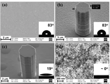
roughness height was controlled in the range from 0 m to 15 m (with 5 m increments) by fabricating a square array of cylindrical posts with 5 m diameter and 500 m pitch on the silicon wafer. The large pitch was selected to prevent appreciable change in the surface area. The surface wettability was controlled by depositing a nano-smooth thin layer of gold (100 nm thick) or silicon oxide (20 nm thick) with a sputtering technique; the resulting contact angles for de-ionized water droplets were found to be 83 on the gold surface and 19 on the silicon oxide surface. To explore the effect of porosity, we used a thin porous layer (about 600-nm thick) made of silicon oxide nanoparticles (23-nm diameter), deposited according to the LbL process. The porous layer further enhances the apparent wettability (the contact angle decreases to ~0) with respect to the smooth silicon oxide surface. On the other hand, the roughness height change due to the porous layer is negligible ( 0.016 m). Representative images of the engineered surfaces are shown in Fig. 3.
8
Table I. Measured values of surface features and CHF data.* Zuber’s correlation [17] for an upward facing flat plate predicts CHF=1100 kW/m2
Pattern Fabrication
(substrate is nano-smooth sapphire in all cases)
Roughness (μm) Porosity Vol. Fraction (%) Contact Angle (degrees) CHF (kW/m2)
Ra Rq Rz Static Advancing Receding
1 Smooth Uncoated Heater (reference) No fabrication required <0.01 <0.01 <0.01 0 75 82 48 92077* 2 Smooth Non-porous Hydrophilic
Electron beam deposition of 20nm SiO2 layer <0.01 <0.01 0.02 0 <5 0 0 1009103 3 Smooth Non-porous
Hydrophobic
Electron beam deposition of 20nm SiO2 layer
Chemical vapor deposition of fluorosilane 0.01 0.01 0.03 0 112 131 81 968173 4 Smooth Porous
Hydrophilic
LbL deposition of 50nm diameter SiO2
particles, fifty layers 0.14 0.18 0.78 50 <5 0 0 1617177
5
Smooth Porous Hydrophobic
LbL deposition of 50nm diameter SiO2 particles, fifty layers
Chemical vapor deposition of fluorosilane
0.12 0.15 0.72 50 137 160 97 344
6
Rough Non-porous Hydrophilic
Photolithography of 20μm diameter, 15μm tall posts; 0.5mm pitch
Electron beam deposition of 20nm SiO2 layer
2.69 4.54 14.96 0 <5 0 0 106358 7
Rough Non-porous Hydrophobic
Photolithography of 20μm diameter, 15μm tall posts; 0.5mm pitch
Electron beam deposition of 20nm SiO2 layer
Chemical vapor deposition of fluorosilane
2.62 4.43 15.22 0 113 132 86 1067163
8
Rough Porous Hydrophilic
Photolithography of 20μm diameter, 15μm tall posts; 0.5mm pitch
LbL deposition of 50nm diameter SiO2 particles, fifty layers
2.22 3.95 14.08 50 5 0 0 1591111 9
Rough Porous Hydrophobic
Photolithography of 20μm diameter, 15μm tall posts; 0.5mm pitch
LbL deposition of 50nm diameter SiO2 particles, fifty layers
Chemical vapor deposition of fluorosilane
Figure 3. SEM images of fabricated samples for LFP tests: (a) smooth Au layer; (b) 15-m posts on smooth Au layer; (c) 15-m posts on smooth SiO2 layer; (d) layer-by-layer SiO2 layer. Insets show static contact
angle for 10-L water droplets on the fabricated samples (a) smooth Au (83o), (b) Au with micro-posts (83o),
(c) SiO2 layer (19o), (d) nano-porous SiO2 layer (~0o).
Table II shows the LFP temperature data. The LFP increases with the height of the micro-posts on all surfaces tested in this study, but the magnitude of the increase is distinctively higher on the porous surface. For a given height of the posts, the LFP increases with wettability. As a result, the hydrophilic porous surface with micro-posts can be considered an optimum (within the limits of this study), exhibiting the highest LFP at 453C, which is even beyond the critical point of water (374C).2 Why do porosity, wettability and the micro-posts result in such a high LFP? High-speed imaging of the evaporating droplets sheds light on the physical mechanisms, when we focused on the intermittent solid-liquid contacts in film boiling. We observed thin liquid filaments intermittently connecting the droplet to the solid surface on the samples with posts (Fig. 4b), whereas the filaments were not observed on the surfaces without micro-posts (Fig. 4a). However, even in the presence of liquid filaments, the evaporation process was quite different depending on whether the surface was nano-porous or not. The gold and silicon oxide surfaces without nano-porosity stably sustained the liquid filaments, typically for a few milliseconds, without triggering any perturbation (Figs. 4b and c). By contrast, the nano-porous surfaces instantaneously reacted to the filament contacts with violent splashes of tiny droplets around the large evaporating droplet (Fig. 4d). This splashing severely disturbed the liquid-vapor interface and prevented the establishment of a stable vapor film at nominal surface temperatures as high as 453C.
2Note that the reported values of LFP are the nominal temperatures of the test surface. Obviously, the local temperature at which the liquid-solid contact occurs must be below the critical point.
In Refs. [32,36] we argue, and justify semi-quantitatively, that (i) the micro-posts augment the frequency of the intermittent contacts between the liquid and the surface, (ii) the wettability increases the residence time of the liquid on the surface, and (iii) the surface pores trigger bubble nucleation that disrupt the vapor film, at temperatures well above those at which a hydrodynamic instability may set in.
Figure 4. Photographs of evaporating water droplets on test surfaces held at 400C: (a) Au without posts; (b) Au with 15-m posts; (c) SiO2 with 15-m posts; (d) nano-porous SiO2 layer with 15-m posts. Arrows
show location of droplet-to-surface bridging by liquid filaments. Table II. LFP temperatures on the engineered surfaces.
Micro post height Hydrophobic, non-porous (Au) Hydrophilic, non-porous (SiO2) Hydrophilic, 50% porosity (Porous SiO2) 0 m 2645C 2745C 3595C 5 m 2955C 3305C 4105C 10 m 2955C 3305C 4405C 15 m 2905C 3255C 4535C
3. THERMAL PERFORMANCE LIMITERS IN LIGHT WATER REACTORS (LWRs)
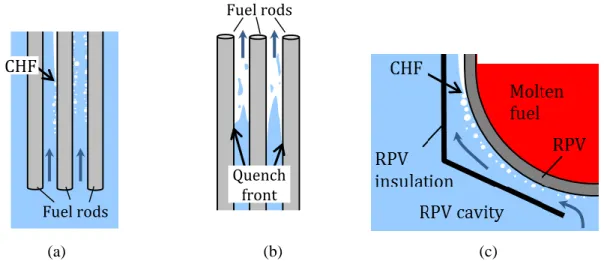
The CHF and quenching heat transfer phenomena described in Section 2 are the key thermal-hydraulic phenomena limiting the performance of Pressurized Water Reactors (PWRs) and Boiling Water Reactors (BWRs), collectively known as LWRs. CHF is the primary limit during a loss-of-flow accident (LOFA) or an overpower transient in which departure from nucleate boiling (PWR) or liquid film dryout (BWR) can occur due to either a reduction in the coolant flow or an excursion of the heat flux (Fig. 5a). When CHF occurs, the nuclear fuel overheats and can be damaged, resulting in fission product release; therefore, regulations [37] establish limits on the allowable heat flux at the cladding surface to avoid CHF. Specifically, a Minimum Departure From Nucleate Boiling Ratio (MDNBR), defined as the minimum ratio of the CHF to the operating heat flux in the core, is imposed in PWRs; and a Minimum Critical Power Ratio
(MCPR), defined as the minimum ratio of the fuel assembly power corresponding to liquid film dryout to the operating fuel assembly power, is imposed in BWRs.
Quenching heat transfer occurs in the wake of a loss-of-coolant accident (LOCA), when the Emergency Core Cooling System (ECCS) injects cold water into the core, to reduce the temperature of the fuel that is no longer covered by the primary coolant (Fig. 5b). The speed at which the quenching process (quenching front) progresses throughout the core determines the maximum fuel temperature attained during the accident, which in turn determines the safety margin to fuel damage. Regulations [38] mandate that during LOCAs the peak cladding temperature (PCT) remain below a postulated limit (1200C, to prevent runaway oxidation of the zirconium cladding), which is ensured by limiting the steady-state reactor power and maximizing the rate of ECCS injection.
In some new designs, such as Westinghouse’s AP1000, the 1200C limit is not challenged since the fuel is not uncovered even during the worst postulated LOCA. However, a new limit arises during hypothetical beyond-design-basis severe accidents in which the fuel melts and relocates to the bottom of the Reactor Pressure Vessel (RPV). In such situations it is desirable to retain the molten fuel within the RPV, to eliminate the possibility of molten fuel/concrete interaction and steam explosion. This In-Vessel Retention (IVR) strategy consists of flooding the reactor cavity, so that the decay heat from the molten fuel is removed by conduction through the RPV wall and flow boiling on the outer surface of the RPV. The decay heat removal is then limited by the occurrence of flow-boiling CHF at the RPV outer surface (Fig. 5c). If CHF occurred, the RPV would breach and the molten fuel would flow into the containment (IVR failure). Note that CHF in IVR is very different from the in-core CHF situation depicted in Fig. 5a: it occurs at much lower pressure (0.1-0.3 MPa vs. 15 MPa), lower mass flux (<1000 kg/m2s vs. >3000 kg/m2s), in a channel with a unique geometry (bottom-facing hemispherical gap vs. vertical rod bundle) and on a surface made of a different material (carbon steel vs. zirconium alloy). However, because of the proportionality between decay power and nominal core power, CHF in the IVR situation can also constrain the power allowable during normal operation.
(a) (b) (c)
Figure 5. Schematic representation of CHF and quenching in the (a) LOFA, (b) post-LOCA and (c) IVR situations in a PWR. Fuel rods CHF Fuel rods Quench front
Accurate quantification of the thermal margins in the situations described above is obviously important to plant safety, but also to plant economics. Overly conservative margins limit the core power density (i.e., power produced per unit volume of the reactor core), thus hurting the reactor’s economic performance. Because capital costs of a typical LWR constitute 65% of the total busbar electricity cost, extracting more power from a reactor or, for given power, reducing the physical size of the reactor reduces the total cost of electricity from nuclear energy considerably. Therefore, there are powerful economic incentives to eliminate un-necessary conservatism in the determination of the thermal margins. It comes down to a more accurate prediction of flow-boiling CHF and quenching heat transfer, including the effects of the surface characteristics.
4. OPPORTUNITIES FOR THERMAL MARGIN ENHANCEMENT IN LWRS
Historically, experiments and analyses in support of LWR safety have been focused on reproducing the correct in-reactor thermal-hydraulic conditions, e.g. see the comprehensive FLECHT SEASET program [39], but essentially have ignored the effects of surface characteristics on CHF and quenching heat transfer. This is understandable as surface conditions are hard to predict and control during reactor operation. However, as shown in Section 2, these effects are not negligible, and since we are beginning to understand them at a more systematic and fundamental level, the time seems ripe to start incorporating them in tests and analyses, in particular in the determination of the reactor thermal margins.
4.1 Normal Operating Conditions
In LWR plants heat generation by nuclear fission takes place within solid cylindrical pellets (10 mm by 10 mm) of uranium dioxide (UO2) fuel, encapsulated in a thin (0.5-0.7 mm), sealed tube called the cladding.
Heat removal by the water coolant occurs on the outer surface of the cladding. The cladding is made of a zirconium alloy. While there exist many variations of such alloy, the two with the largest service experience are the Zircaloy-2 and Zircaloy-4 alloys, both having nominal composition Zr, 1.2-1.7 Sn, <0.2 Fe,Cr,Ni (wt%). Advanced zirconium alloys with less Sn (0-1 wt%) and a small addition of Nb (1 wt%) to reduce corrosion and hydrogen pickup are also available, e.g. Westinghouse’s ZirloTM, Areva’s M5TM. The cladding is fabricated by extrusion, cold drawing/pilgering and belt grinding, which gives it a smooth surface finish. Figure 6a shows the surface of as-fabricated Zircaloy cladding prior to in-reactor service. The surface appears smooth and shiny clean. However, a very thin (2-5 nm) oxide layer ZrO2 is always present from
oxidation in air. Typical surface roughness is Ra0.1-0.6 m [40], and static contact angle (measured at
(a) (b)
(c) (d)
Figure 6. (a) As-fabricated Zircaloy cladding tubes; (b) Time evolution of oxide layer thickness of zirconium alloys in reactor operation (from [42]); SEM images of oxide layer in (c) pre-transition stage (adapted from [43]), and (d) transition/post-transition stage showing heavily cracked oxide layer (adapted from [44]).
The aggressive environment present in the reactor core changes the cladding surface mainly through cladding oxidation (corrosion) and CRUD deposition. Upon exposure to the high-temperature (280-320C) water coolant, the surface of the cladding rapidly oxidizes in a passivating manner, by forming a highly-dense zirconium oxide layer. This layer hinders further oxygen diffusion to the metal substrate, thus slowing down further cladding oxidation. The oxide layer is made of ZrO2 and, for Zircaloy, also Zr(Cr,Fe)2
precipitates in metallic form as well as tin oxide SnO [42]. The oxide layer thickness depends on the duration of the in-core service (i.e discharge burnup), the composition and distribution of the Zr(Cr,Fe)2
precipitates (which anodically protect the substrate), and the specific coolant chemistry of the reactor (e.g. hydrogen water chemistry, lithium hydroxide addition and zinc injection in PWRs, noble metal chemical addition in BWRs). However, given the coolant chemistry, the evolution of the oxide layer is fairly predictable with an initial growth limited by inter-granular diffusion of oxygen exhibiting a cubic root dependence on time (pre-transition stage), followed by periodic oxide layer breakdown/growth cycles (transition stage), followed by linear growth (post-transition stage), as shown in Fig. 6b. The morphology of the oxide layer in the pre-transition and transition/post-transition stages is shown in Fig. 6c and 6d, respectively. It can be seen that the oxide layer is initially a compact (non-porous) oxide; as such, no
Zr
ZrO
2Zr
significant effects on CHF and quenching are expected in this initial phase. However, in the transition and post-transition stages the oxide layer develops nanoporosity at the grain boundaries, and microcracks parallel to the cladding surface; this evolution could be due to cracking from accumulation of compressive stresses in the oxide, or from crystalline phase transition transformation of ZrO2 (from tetragonal to monoclinic), or
from oxidation of the Zr(Cr,Fe)2 precipitates [42]. These pores/cracks range from 1 to 500 nm in size [45]
and can be interconnected, thus letting the coolant percolate to the metal substrate, which compromises the corrosion protection function of the oxide layer [42]. Typical oxide thicknesses at fuel discharge (at 60 MWd/kgHM) are between 10 and 60 m [42]. Roughness <0.5 m and porosity of up to 15% are typical for
the thick oxide layer at discharge [45]. The volume fraction of the larger cracks appears to be order of 20-30% (Fig. 6d), although the cracks may have opened considerably upon cooling of the samples. Interestingly, it was found that the contact angle of Zircaloy is significantly reduced by both oxidation and gamma irradiation; the latter effect is known as Radiation Induced Surface Activation (RISA) phenomenon. Lab samples of oxidized and gamma-irradiated Zircaloy specimens have exhibited contact angles as low as 10-20 [19,41].
Since the characteristics of the oxidation layer are qualitatively similar to those of CRUD, their implications on CHF and quenching heat transfer will be discussed together with CRUD below.
CRUD (Chalk River Unidentified Deposits) refers to deposition of tenacious scale on the cladding surface driven by subcooled nucleate boiling in PWRs (occurring in the upper region of some fuel assemblies) and saturated nucleate boiling in BWRs (occurring primarily in the lower region of the core) (Figures 7a and 7b). The source of CRUD is mainly corrosion products (NiO, Fe3O4, NiFe2O4 with Cr and Zn additions and
sometimes ZrO2) from steam generator corrosion in PWRs, and iron, nickel and copper oxides from
corrosion in the feedwater system in BWRs [46]. Figures 7c through 7g show images of CRUD deposits from various U.S. nuclear plants. CRUD composition and morphology vary somewhat from plant to plant, however, it can be seen that in general CRUD is porous scale with submicronic pores and often featuring large (2-10 m) vapor chimneys, through which steaming occurs (Fig. 7h). Typical CRUD thicknesses can range from a few microns up to 120 m; typical surface roughness, porosity and room-temperature static contact angle of CRUD flakes are 2.5 m, 45-50% and 303, respectively [52].
Towards the upper end of the thickness range, CRUD constitutes a significant thermal resistance, which can increase the cladding temperature by tens of degrees [53]. This can lead to CRUD Induced Localized Corrosion (CILC), potentially resulting in pinhole-leak-type failure of the cladding. However, if CRUD
thickness is limited to 10-20 m, its thermal resistance is negligible and its effect on the boiling heat transfer coefficient and CHF may actually be beneficial. Data with relatively thin (3-38 m) porous magnetite deposits simulating CRUD on PWR steam generator tubes show an increase of the boiling heat transfer
coefficient by as much as 40% in both subcooled and saturated boiling at pressure 4.2-4.4 MPa [54]. The Westinghouse’s WALT loop data [53] also showed that, below 15-40 m thickness, CRUD deposits improve heat transfer. Like the CHF-enhancing engineered surfaces reported in Table I, CRUD features an interconnected porous structure made of hydrophilic particles; therefore, CHF enhancement is expected. Similar considerations apply to the porous ZrO2 layer in the transition and post-transition stages of Zircaloy
oxidation.
Accurate quantification of CHF enhancement by CRUD or ZrO2 porous layers is not possible at this time
because the CHF data in Table I are not reactor prototypical in two ways: first, they are for a pool (vs. flow) boiling situation; second, they are for atmospheric (vs. high) pressure. Flow boiling tests exist for water at atmospheric pressure in tubes coated with porous layers of alumina nanoparticles, which suggest that between 50 and 80% flow-boiling CHF enhancement is possible, depending on mass flux [55]. Unfortunately, data for surface effects on flow-boiling CHF at high pressure do not exist, thus we are forced to extrapolate from the atmospheric-pressure database. If we assume that capillary wicking of liquid through the interconnected CRUD or ZrO2 porosity is responsible for CHF enhancement, then we expect the
governing variables to be: porosity volume fraction (), pore diameter (Dp), pore effective length 4
(L), surface tension (), fluid viscosity (), and fluid density (). Through dimensional analysis it is straightforward to identify the governing groups to be itself, the ratio Dp/L, and the pore Reynolds number Rep Dp/
2
. While and Dp/L are simple geometric quantities, the Reynolds number strongly depends
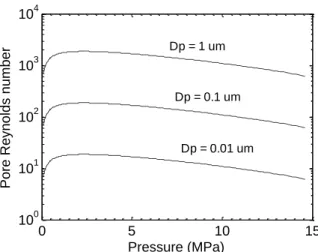
on the coolant pressure (or the corresponding saturation temperature). Figure 8 shows the variation of the pore Reynolds number with coolant pressure and pore diameter. It can be seen that for any given pore diameter, the Reynolds number has a maximum at about 2.5 MPa; interestingly, the values of Rep at
atmospheric pressure and PWR pressure are very similar, suggesting that the capillary wicking observed in our experiments should be effective in supplying fresh liquid to the surface also at reactor conditions. However, tests in rod bundle geometry with prototypical reactor materials and thermal-hydraulic conditions will be needed for confirmation of the flow-boiling CHF gains in a nuclear plant.
4 Alternatively, one could use tortuosity.
(a) (from [47]) (b) (from [47])
(c) (from [48]) (d) (from [49]) (e) (from [50])
(f) (from [51]) (g) (from [48]) (h) (courtesy of M. Short, MIT)
Figure 7. Images of heavily CRUDed rods in (a) PWR fuel assembly and (b) BWR fuel assembly. (c)-(g): SEM images of CRUD deposits from various U.S. plants. (h) Schematic of CRUD deposits.
Figure 8. Pore Reynolds number as a function of pore diameter and coolant pressure.
4.2 Post-LOCA
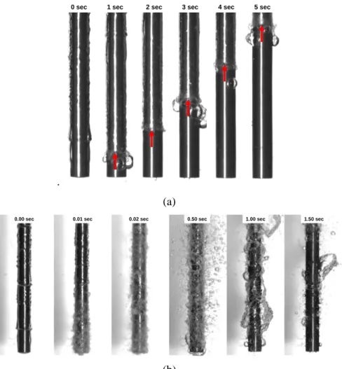
In a post-LOCA situation, the oxidized and CRUDed surface of the cladding may reach very high temperatures (up to 1200C) before being exposed to cold water at near-atmospheric pressure from the ECCS. As suggested by the results in Table II, the presence of a porous hydrophilic layer on the surface could increase the LFP temperature by 100-200C, which in turn would substantially accelerate quenching of the reactor fuel rods. Figure 9 shows quenching tests (taken from Ref. [32]) in which stainless steel rodlets with a clean surface were compared to rodlets with a surface coated by a porous layer of alumina nanoparticles. The rodlets were pre-heated to 1000C and then rapidly plunged into cold (80C) water; the quenching process was observed with a high-speed video camera, while a thermocouple embedded in the rodlet recorded the temperature vs. time evolution. It can be seen that quenching of the clean rods was a relatively slow process, featuring a well-defined quench front which moved upward at an approximate speed of 7 mm/s. This speed is consistent with measured and calculated quench front speeds for simulated reactor fuel rods [56], and would result in a total quenching time of approximately 530 sec for a core of 3700 mm length. By contrast, quenching of the rods with a coated surface occurred through sudden collapse of the vapor film across the whole rod at an estimated speed of 5000 mm/sec, or three orders of magnitude faster than on the clean surface. Under these conditions, the core quenching time would be limited by the rate at which the water level in the RPV is re-established by the ECCS. Since in a typical PWR the ECCS can refill the RPV at a speed of 60 mm/sec (thus covering the core in 3700/60≈62 sec), the estimated potential gain is 53062=468 sec. If we assume that the hot fuel rod during this time has a linear decay power of 0.8 kW/m and a heat transfer coefficient to steam of 75-100 W/m2K, we estimate that the peak fuel temperature during a post-LOCA could be lowered by 150-200C 5, accordingly increasing the margin to the 1200C limit.
4.3 In-Vessel Retention
For IVR, the surface of interest is the outer surface of the RPV. The RPV is made of carbon steel grade SA-508, in Europe known as 16MND5-Cl.3. The nominal composition is Fe, <0.25 C, 1.2-1. 5 Mn, 0.15-0.4 Si,
5 This estimate assumes a linear thermal capacity of 200 J/K-m for a typical PWR fuel rod.
0 5 10 15 100 101 102 103 104 Pressure (MPa) Pore Re ynolds number Dp = 0.1 um Dp = 1 um Dp = 0.01 um
0.4-1.0 Ni, 0.45-0.60 Mo (wt. %). The RPV surface finish varies from vendor to vendor; however roughness order of 6 m is typical [57]. During its 60-year lifetime, the RPV outer surface progressively oxidizes, a process which is greatly accelerated by the hot and wet environment present in the containment during a severe accident. Oxide layer thicknesses 200 µm are possible, with composition being a compact layer of Fe3O4 near the substrate and a layer of FeO(OH), which is porous and hydrophilic [58]. Figures 10a and 10b
show the surface of clean SA-508 and heavily oxidized SA-508, respectively. The room-temperature, static contact angle of clean and oxidized SA-508 is 90 and 40, respectively [59]. Limited tests with oxidized SA-508 in a loop simulating IVR conditions suggest that flow-boiling CHF on oxidized SA-508 is 85% higher than for traditional stainless steel (Grade 316) [59]. Therefore, the previous CHF database used for IVR evaluation of the AP1000 [60] as well as the European database [61,62] appear to be enormously conservative.
Furthermore, in IVR situations the RPV cavity would be flooded with water containing boric acid and lithium hydroxide, as well tri-sodium phosphate (TSP) or sodium tetraborate(STB) 6. Additional debris may be present (e.g. insulation fibers, paint chips, dust) the nature and amount of which depends on the accident initiator and also on containment cleanliness prior to the accident. A generic example of fibrous debris potentially present in the containment following a LOCA is shown in Figure 10c. Boiling of this “soup” on the RPV outer surface would cause deposition of a porous scale which may have characteristics similar to CRUD, which may further increase the CHF. However, CHF data for SA-508 with scale deposits are not available at the present moment
A summary of the Zry cladding and RPV surface characteristics relevant to CHF and quenching heat transfer is reported in Table III.
Table III. Characteristics of Zry cladding and RPV surfaces.
Zry cladding SA-508 RPV
As-fabricated In-service As-fabricated Post-accident
Composition ZrO2, 2-5 m thick NiO, Fe3O4, NiFe2O4, ZrO2, 10-100 m thick Fe3O4 Fe3O4, FeO(OH), B, Li, TSP, 200 m thick
Roughness Ra 0.1-0.6 m Ra 0.5-3.0 m Ra 6 m n/a (presumably high)
Wettability (contact angle)
70-80 10-30 90 40
Porosity Non porous 40-50% Non porous Porous
6 Boric acid and lithium hydroxide are used in the PWR coolant for reactivity control and pH control, respectively. TSP and STB are used in PWR containments to minimize fission products volatility during a severe accident.
.
(a)
(b)
Figure 9. Quenching of stainless steel rodlets (4.8 mm diameter; 50 mm length) in water at atmospheric pressure and 80C. (a) clean surface; (b) surface with porous layer of alumina nanoparticles. Initial rodlet temperature: 1000C.
(a) (b) (c)
Figure 10. SEM images of (a) fresh SA-508, and (b) heavily-oxidized SA-508 (from [63]). (c) Fibrous debris (courtesy of G. Zigler, Senior Scientist/Engineer, ENERCON).
1 sec 2 sec 3 sec 4 sec 5 sec 0 sec
1.50 sec 0.01 sec 0.02 sec 0.50 sec
5. CONCLUSIONS AND FUTURE WORK
Figure 11 synoptically summarizes the contents of this paper. The title asked if corrosion and CRUD can actually improve safety margins in nuclear plants. The answer at this time can only be (an optimistic) “maybe”. While it is obvious that oxidation and some CRUD may create cladding and RPV surface characteristics that are conducive to CHF enhancement and quenching heat transfer acceleration, more information is needed to quantify the magnitude of these effects in nuclear plants.
Figure 11. Synopsis of relations between the service environment, surface characteristics, boiling phenomena and thermal margins in LWRs.
Future work should focus on several important knowledge gaps that exist at the present moment:
- Additional fundamental studies of surface effects on flow-boiling CHF enhancement and quenching acceleration are needed. Specifically, having determined in [26,35] the key role played by porosity, it will now be necessary to elucidate the effects of pore size and shape, pore volume, pore interconnection and porous layer thickness. Particular attention should be paid to thickness: a thick (order of 50 m and above) layer would likely constitute a large thermal resistance and result in higher cladding temperatures, and possibly also lower CHF. On the other hand, current data suggest that a thin (e.g. <20 m) porous layer increases both the heat transfer coefficient and CHF.
- All boiling CHF data presented in this paper are for a boiling crisis of the Departure from Nucleate Boiling (DNB) type, which is relevant to the PWR conditions. However, dryout-type CHF conditions dominate in BWRs. Therefore, data for surface effects on dryout-type CHF are needed.
- CHF and quenching tests for surface effects at prototypical reactor conditions are needed, including actual CRUD and substrate materials (Zr alloys), rod bundle geometry, and, for CHF, also full reactor pressure and temperature conditions. Contact angles data for oxidized, CRUDded and irradiated cladding at reactor temperature and pressure are also needed, but currently lacking7.
7 It is hard, but not impossible, to measure the contact angle of water droplets at temperatures as high as 300C and pressures as high as 15 MPa [64].
Oxidation CRUD deposition
Porosity Roughness Wettability CHF enhancement Quenching acceleration MDNBR (PWR) CPR (BWR) In-reactor environment Surface characteristics Boiling phenomena Thermal margins in LWRs CHF in IVR PCT in LOCA
- Robust and validated models to predict the effects of CRUD and oxidation on CHF and quenching heat transfer are needed. Models of various complexities for determining the thermal resistance associated with CRUD deposits have been proposed in the past [54,65,66], some are under development now [67], and represent a good starting point.
- The interplay of surface effects and chemicals in the coolant (e.g. boric acid, lithium hydroxide, and zinc acetate in PWRs; zinc oxide and noble metals in BWRs) should be investigated. Chemicals can affect CHF and quenching in two ways: (i) change coolant properties (especially surface tension), and (ii) come out of solution and deposit on the cladding upon boiling. Some limited data already exist and suggest that CHF is enhanced by deposition of chemicals on the boiling surface, but more systematic studies are needed [68-70].
- If credit is to be taken for surface effects, a suitable regulatory framework and industry practices have to be developed: the challenge is to ensure predictability of cladding surface conditions throughout the irradiation cycle. This may mandate periodic inspection of the cladding surface, CRUD deposition limits, and/or possibly pre-treatment or periodic conditioning of the cladding surface, to ensure conditions favorable to CHF enhancement and quenching acceleration are maintained.
ACKNOWLEDGMENTS
AREVA NP is gratefully recognized for supporting the work on the effects of surface characteristics on CHF and quenching heat transfer. Special thanks to Bilge Yildiz, Mostafa Youssef, Michael Short, Peter Griffith, Neil Todreas, Eric Forrest, Ron Ballinger at MIT, Mike Pop at AREVA, Arthur Motta at Penn-State and Gilbert Zigler at ENERCON for providing valuable suggestions and information.
NOMENCLATURE
Acronyms
AP1000 Advanced Passive 1000
ASME American Society of Mechanical Engineers BWR Boiling Water Reactor
CHF Critical Heat Flux
CILC CRUD Induced Localized Corrosion CRUD Chalk River Unidentified Deposits DNB Departure from Nucleate Boiling DOE Department Of Energy
ECCS Emergency Core Cooling Systems EPRI Electric Power Research Institute IVR In-Vessel Retention
LbL Layer-by-Layer coating LFP Leidenfrost Point
LOCA Loss Of Coolant Accident LOFA Loss Of Flow Accident LWR Light Water Reactor
MCPR Minimum Critical Power Ratio
MDNBR Minimum Departure from Nucleate Boiling Ratio MIT Massachusetts Institute of Technology
NRC Nuclear Regulatory Commission PWR Pressurized Water Reactor
RISA Radiation Induced Surface Activation RPV Reactor Pressure Vessel
SEM Scanning Electron Microscope STB Sodium tetraborate
TSP TriSodium Phosphate
Symbols
Dp Pore diameter L Effective pore length
Nu Nusselt number
Pr Prandtl number
Ra Average surface roughness
Rz Ten-point mean roughness Re Reynolds number
Rep Pore Reynolds number
Porosity volume fraction
/D Relative roughness
Viscosity
Fluid density
REFERENCES
[1] A. Mills, Heat Transfer, 2nd Ed., Prentice Hall, Upper Saddle River, NJ, 1999.
[2] V.P. Carey, Liquid-Vapor Phase-Change Phenomena, Taylor and Francis, 2nd Ed., 2008.
[3] S. Witharana, B. Phillips, S. Strobel, H. D. Kim, J.-B. Chang, J. Buongiorno, K. Berggren, L. Chen, Y. Ding, Bubble Nucleation on Nano- to Micro-size Cavities and Posts: An Experimental Validation of Classical Theory, J. Appl. Phys, 112, 064904 (2012).
[4] K. Sefiane, On the role of structural disjoining pressure and contact line pinning in critical heat flux enhancement during boiling of nanofluids, Appl. Phys. Lett. 89, 044106 (2006).
[5] K.-H. Chu, R. Enright, E.N. Wang, Structured surfaces for enhanced pool boiling heat transfer, Appl. Phys. Lett., 100(24), 241603-00 (2012).
[6] S. Kandlikar, A Theoretical Model to Predict Pool Boiling CHF Incorporating Effects of Contact Angle and Orientation, J. Heat Transfer, Vol. 123, 1071-1079 (2001).
[7] S.J. Kim, I.C. Bang, J. Buongiorno, L.W. Hu, Effects of nanoparticle deposition on surface wettability influencing boiling heat transfer in nanofluids, Appl. Phys Lett., Vol. 89, 153107, Issue 15 (2006). [8] S.J. Kim, I.C. Bang, J. Buongiorno, L.W. Hu, Surface Wettability Change during Pool Boiling of
Nanofluids and its effect on Critical Heat Flux, Int. J. Heat Mass Transfer, Vol. 50, 4105-4116 (2007). [9] E. Forrest, E. Williamson, J. Buongiorno, L.W. Hu, M. Rubner, R. Cohen, Augmentation of Nucleate
Boiling Heat Transfer and Critical Heat Flux Using Nanoparticle Thin-Film Coatings, Int. J. Heat Mass Transfer, 53, 58–67 (2010).
[10] H.S. Ahn, C. Lee, H.D. Kim, H.J. Jo, S.H. Kang, J.W. Kim, J.S. Shin, M.H. Kim, Pool boiling CHF enhancement by micro/nanoscale modification of zircaloy-4 surface , Nucl. Eng. Des., 240, 10, 3350-3360 (2010).
[11] H. S. Ahn, S.H. Kang; H.J. Jo; H.D. Kim; M.H. Kim, Visualization study of the effects of nanoparticles surface deposition on convective flow boiling CHF from a short heated wall, Int. J. Multiphase Flow, v 37, n 2, p 215-28 (2011).
[12] J. Ramilison, P. Sadasivan, J. Lienhard, Surface Factors Influencing Burnout on Flat Heaters, J. Heat Transfer, vol. 114, pp. 297-290 (1992).
[13] J. Chang, S. You, Enhanced boiling heat transfer from micro-porous surfaces: effects of a coating compositions and method, Int. J. Heat Mass Transfer, vol. 40, no. 18, pp. 4449-4460 (1997).
[14] S. You, J. O'Connor, A painting technique to enhance pool boiling heat transfer in saturated FC-72, J. Heat Transfer, no. 117, pp. 387-393 (1995).
[15] S. Liter, Pool-boiling CHF enhancement by modulated porous-layer coating: theory and experiment, Int. J. Heat Mass Transfer, no. 22, pp. 4287-4311 (2001).
[16] M. Toprak, S. Li, B. Palm, M. Muhammed, The use of a nano- and microporous surface layer to enhance boiling in a plate heat exchanger, J. Heat Transfer, vol. 131, no. 10 (2009).
[18] J. Sinha, L.E. Hochreiter, F.-B. Cheung, Effects of surface roughness, oxidation level, and liquid subcooling on the minimum film boiling temperature, Experimental Heat Transfer, v 16, n 1, p 45-60 (2003)
[19] T. Takamasa, T. Hazuku, K. Okamoto, K. Mishima, M. Furuya, Radiation Induced Surface Activation on Leidenfrost and Quenching Phenomena, Exp. Therm. Fluid Sci., 29, 267-274 (2005).
[20] L.A. Bromley, N.R. Leroy, J.A. Robbers, Heat transfer in forced convection film boiling, Industrial and Engineering Chemistry, 45 (12) 2639-2646 (1953).
[21] T.G. Theofanous, T.N. Dinh, High heat flux boiling and burnout as microphysical phenomena: mounting evidence and opportunities, Multiphase Science and Technology, Vol. 18, No. 1, pp. 1-26 (2006).
[22] R.N. Wenzel, Surface roughness and contact angle (letter), J. Physical Colloid Chemistry, 53, 9, 1466 (1949).
[23] P. Berenson, Experiments on pool-boiling heat transfer, Int. J. Heat Mass Transfer, no. 5, pp. 985-999 (1962).
[24] L. Pioro, W. Rohsenow, S. S. Doerffer, Nucleate Pool-Boiling Heat Transfer. I: Review of Parametric Effects of Boiling Surface, Int. J. Heat Mass Transfer, Vol. 47, No. 23, pp. 5033-5044 (2004).
[25] Y. Polezhaev, S. Kovalev, Modeling heat transfer with boiling on porous structures, Thermal Engineering, vol. 12, pp. 617-620 (1990).
[26] H. O’Hanley, C. Coyle, J. Buongiorno, T. McKrell, L. W. Hu, M. Rubner, R. Cohen, Separate Effects of Surface Roughness, Wettability and Porosity on the Boiling Critical Heat Flux, Applied Physics Letters, 103, 024102 (2013).
[27] H. O’Hanley, Investigation into the Effects of Individual Surface Parameters on Boiling Heat Transfer and Critical Heat Flux and Optimization of Boiling Surfaces through Nano-engineered Surface Features, M.S. Thesis, Dept. Nuclear Sci. Eng., MIT, June 2012.
[28] M. Rubner, D. Lee, Z. Gemici, R. Cohen, Multilayers of oppositely charged SiO2 nanoparticles: Effect of surface charge on multilayer assembly, Langmuir, no. 23, pp. 8833-8837 (2007).
[29] U. Heisig, S. Schiller and S. Panzer, Electron bean technology, Wiley, 1995.
[30] D. Mattox, Handbook of Physical Vapor Deposition (PVD) Processing, Noyes Publications, 1998. [31] H. Kim, T. McKrell, G. Dewitt, J. Buongiorno, L.W. Hu, On the Quenching of Steel and Zircaloy
Spheres in Water-Based Nanofluids with Alumina, Silica and Diamond Nanoparticles, Int J. Multiphase Flow, 35, 427–438 (2009).
[32] H. Kim, T. McKrell, J. Buongiorno, L.W. Hu, Nanoparticle Deposition Effects on the Minimum Heat Flux Point and Quench Front Speed during Quenching of Rodlets and Spheres in Water-Based Alumina Nanofluids, Int. J. Heat Mass Transfer, 53, 1542–1553 (2010).
[33] P.L. Berenson, Film-boiling heat transfer from a horizontal surface, J. H. Transfer 83, 351-358 (1961). [34] R.E. Henry, A correlation for the minimum film boiling temperature, AIChE Symposium Series 70
[35] H. Kim, B. Truong, J. Buongiorno, L.W. Hu, On the effect of surface roughness, wettability and nano-porosity on Leidenfrost phenomena, Appl. Phys. Lett., 98, 083121 (2011).
[36] H. Kim, B. Truong, J. Buongiorno, L.W. Hu, Effects of micro/nano-scale surface characteristics on the Leidenfrost point temperature of water, J. Thermal Science Tech., Vol. 7, No. 3, 453-462 (2012). [37] Nuclear Regulatory Commission, Standard Review Plan for the Review of Safety Analysis Reports for
Nuclear Power Plants: LWR Edition — Transient and Accident Analysis, NUREG-0800, Chapter 15, 3.1-3.2, Rev. 2, 2007.
[38] Nuclear Regulatory Commission, Acceptance criteria for emergency core cooling systems for light-water nuclear power reactors, 10 CFR 50.46, rev. Aug. 28, 2007, Washington, DC.
[39] L.E. Hochreiter, Full-Length Emergency Cooling Heat Transfer Separate Effects and Systems Effects Tests (FLECHT SEASET) Program Final Report, WCAP-10926, Westinghouse Electric Corporation, Nov. 1985.
[40] Mihai Pop, Personal Communication, AREVA NP Inc., February 2, 2013.
[41] T. Otsuka, T. Isotani, K. Nakayama, N. Morishige, K. Hashizume, M. Sugisaki, T. Tanabe, On the wettability change of oxidized and gamma irradiated Zircaloy, Paper 1049, Proc. Water Reactor Fuel Performance Meeting, Oct. 2-6, 2005, Kyoto, Japan.
[42] T.R. Allen, R.J.M. Konings, A.T. Motta, Corrosion of Zirconium Alloys, Chapter 5.03 in
Comprehensive Nuclear Materials, Oxford: Elsevier, 49-68, 2012.
[43] A. Ly, A. Ambard, M. Blat-Yrieix, L. Legras, P. Frankel, M. Preuss, C. Curfs, G. Parry, Y. Bréchet, Understanding Crack Formation at the Metal/Oxide Interface During Corrosion of Zircaloy-4 Using a Simple Mechanical Model, J. ASTM Int., 8(9) (2011).
[44] M. Preuss, P. Frankel, S. Lozano-Perez, D. Hudson, E. Polatidis, N. Ni, J. Wei, C. English, S. Storer, K. Chong, M. Fitzpatrick, P. Wang, J. Smith, C. Grovenor, G. Smith, J. Sykes, B. Cottis, S. Lyon, L. Hallstadius, B. Comstock, A. Ambard, M. Blat-Yrieix, Studies regarding corrosion mechanisms in zirconium alloys, J. ASTM Int., 8(9) (2011).
[45] P. Billot, J.-C. Robin, A. Girodano, J. Peybernes, J. Thomazet, H. Amanrich, Experimental and Theoretical Studies of Parameters that Influence Corrosion of Zircaloy-4, in Zirconium in the Nuclear Industry, 10th Int. Symp., pp. 351-377, A.M. Garde and E.R. Bradley (ed.), ASTM 1245, 1994.
[46] J. Chen, On the Interaction between Fuel Crud and Water Chemistry in Nuclear Plants, SKI report 00:5, Studsvik, Nyköping, Sweden, January 2000.
[47] K. Yueh, LWR Fuel Performance & Reliability, EPRI/NEI Course on Materials Reliability in Nuclear Power Systems, June 2008.
[48] Electric Power Research Institute (EPRI), PWR axial offset anomaly (AOA) guidelines, revision 1. Technical Report 1003213, October 2003.
[49] W.A. Byers, J. Deshon, Structure and chemistry of PWR CRUD, paper 7.5, Proc. Int. Conf. Water Chemistry of Nuclear Reactor Systems, October 11-14, 2004, San Francisco, California.
[50] J.A. Sawicki, Evidence of Ni2FeBO5 and m-ZrO2 precipitates in fuel rod deposits in AOA-affected high boiling duty PWR core, J. Nuclear Materials 374, 248–269 (2008).
[51] G. Wang, W.A. Byers, M.Y. Young, Z.E. Karoutas, Westinghouse advanced loop tester (WALT) update, International Conference on Nuclear Engineering, v 3, p 469-475, Proc. 16th Int. Conf. Nuclear Engineering (ICONE-16), May 11–15, 2008, Orlando, Florida.
[52] Z. Karoutas, Westinghouse, Personal communication, December 2010.
[53] Electric Power Research Institute (EPRI), Simulated Fuel CRUD Thermal Conductivity Measurements Under Pressurized Water Reactor Conditions, Technical Report 1022896, October 2011.
[54] J. Uhle, Boiling Heat Transfer Characteristics of Steam Generator U-Tube Fouling, Ph.D. Thesis, Dept. Nuclear Engineering, February 1997.
[55] T.I. Kim; W.J. Chang; S.H. Chang, Flow boiling CHF enhancement using Al2O3 nanofluid and an
Al2O3 nanoparticle deposited tube, Int. J. Heat Mass Transfer, v 54, n 9-10, p 2021-5 (2011).
[56] N. Chikhi, F. Fichot, Reflooding model for quasi-intact rod configuration: Quench front tracking and heat transfer closure laws, Nucl. Eng. Design, 240(10), 3387-3396 (2010).
[57] R. Wright, Westinghouse, Personal communication, May 2010.
[58] K. Atkhen, Personal Communication, Electricite’ De France (EDF) - R&D, December 5th, 2012. [59] G. DeWitt, T. McKrell, J. Buongiorno, L.W. Hu, R.J. Park, Experimental Study of Critical Heat Flux
with Alumina-water Nanofluids in Downward-Facing Channels for In-Vessel Retention Applications, Nuclear Energy Tech., Vol. 45, No. 3, 1-12 (2013).
[60] T-N. Dinh, J. Tu, T. Salmassi, T. Theofanous, Limits of Coolability in the AP1000 Related ULPU-2400 Configuration V Facility, Univ. California, Santa Barbara, CRSS-03/06, June 30, 2003.
[61] S. Rouge, D. Geffraye, Reactor Vessel External Cooling for Corium Retention SULTAN Experimental Program and Modeling with CATHARE Code, Workshop on in-vessel core debris retention and coolability, March 3-6, 1998, Garching, Germany.
[62] M. Caira, G. Caruso, A. Naviglio, S. Rouge, CHF Prediction for Sloping Surfaces, Proc. 5th Int. Topical Meeting on Nuclear Thermal-Hydraulics Operation and Safety (NUTHOS-5), April 14-18, 1997, Beijing, China.
[63] G. L. DeWitt, Investigation of Downward Facing Critical Heat Flux with Water-Based Nanofluids for In-Vessel Retention Applications, Ph.D. Thesis, Dept. Nuclear Sci. Eng., MIT, September 2011. [64] T. Hayashi, T. Hazuku, T. Takamasa, K. Takamori, Contact Angle of Water Droplets in a
High-Temperature, High-Pressure Environment, ICONE12-49418, Proc. 12th Int. Conf. Nuclear Engineering, April 25-29, 2004, Arlington, VA.
[65] C. Pan, B.G. Jones, A.J. Machiels, Wick Boiling Performance in Porous Deposits with Chimneys, ASME HTD Vol. 47, Multiphase Flow and Heat Transfer, edited by V.K. Dhir, J.C. Chen and O.C. Jones, 23rd National Heat Transfer Conference, Denver, Colorado, pp. 15-24 (1985).
[66] B. Shi, B.G. Jones, C. Pan, Parametric study of boiling heat transfer in porous media, Proc. 4th ASME/JSME International Conference on Nuclear Engineering, ICONE-4, v. 1, p. 393-402, March 10-14, 1996, New Orleans, LA.
[67] M. P. Short, “Multiphysics Modeling & Simulation of PWR Fuel CRUD (MAMBA-BDM)”, Paper N9P0385, 9th Int. Topical Meeting Nucl. Thermal-Hydraulics Oper. Safety (NUTHOS-9), Kaohsiung, Taiwan, September 9-13, 2012.
[68] F.J. Arias, Boron dilution effect on boiling heat transfer with special reference to nuclear reactors technology, Annals of Nuclear Energy 36, 1382-1385 (2009).
[69] J. Lee, Y.H. Jeong, S.H. Chang, CHF enhancement in flow boiling system with TSP and boric acid solutions under atmospheric pressure, Nucl. Eng. Des. 240, 3594-3600 (2010).
[70] J. Lee, S.H. Chang, An experimental study on CHF in pool boiling system with SA508 test heater under atmospheric pressure , Nucl. Eng. Des., 250, 720-724 (2012).