Publisher’s version / Version de l'éditeur:
ASHRAE Transactions, 99, 1, pp. 488-495, 1993
READ THESE TERMS AND CONDITIONS CAREFULLY BEFORE USING THIS WEBSITE. https://nrc-publications.canada.ca/eng/copyright
Vous avez des questions? Nous pouvons vous aider. Pour communiquer directement avec un auteur, consultez la première page de la revue dans laquelle son article a été publié afin de trouver ses coordonnées. Si vous n’arrivez pas à les repérer, communiquez avec nous à PublicationsArchive-ArchivesPublications@nrc-cnrc.gc.ca.
Questions? Contact the NRC Publications Archive team at
PublicationsArchive-ArchivesPublications@nrc-cnrc.gc.ca. If you wish to email the authors directly, please see the first page of the publication for their contact information.
NRC Publications Archive
Archives des publications du CNRC
This publication could be one of several versions: author’s original, accepted manuscript or the publisher’s version. / La version de cette publication peut être l’une des suivantes : la version prépublication de l’auteur, la version acceptée du manuscrit ou la version de l’éditeur.
Access and use of this website and the material on it are subject to the Terms and Conditions set forth at
Comparative performances of mechanical smoke exhaust system,
zoned smoke control and pressurized building method of smoke
control
Tamura, G. T.; MacDonald, R. A.
https://publications-cnrc.canada.ca/fra/droits
L’accès à ce site Web et l’utilisation de son contenu sont assujettis aux conditions présentées dans le site LISEZ CES CONDITIONS ATTENTIVEMENT AVANT D’UTILISER CE SITE WEB.
NRC Publications Record / Notice d'Archives des publications de CNRC:
https://nrc-publications.canada.ca/eng/view/object/?id=bf900adc-2369-49ac-ad77-a37e986e31e6 https://publications-cnrc.canada.ca/fra/voir/objet/?id=bf900adc-2369-49ac-ad77-a37e986e31e6
REF
S E R
TH 1
N21d
National Research Conseil national
1*1
Council Canada de recherches CanadaInstitute for lnstitut de
Research in recherche en
Construction construction
Comparative Performances of
~echanical
Smoke Exhaust
System, Zoned Smoke Control,
and Pressurized Building Method
of Smoke Control
by G.T. Tamura and R.A. MacDonald
Reprinted from:
ASH RAE Transactions (99) 1
,
1 993
pp. 488-495
(Paper presented at the ASHRAE Winter Meeting
Held in Chicago, IL. USA, January 23-27, 1993)
(IRC Paper No. 3397)
NRCC 36851
w-P-
3343
IRI: p a p e r @ j ~ e t h - S t r e n s e n I S M - 2 0--
E e v ~ z r e i g h ' t c s t ~ A N A L Y S E C I S T I / 3: C I S T NF:IZ/II:NRC: I F:IZ R e f Ser Rec ei v e d : 06.-.23--94 IRK: p a p e rCOMPARATIVE PERFORMANCES
OF MECHANICAL SMOKE EXHAUST
SYSTEM, ZONED SMOKE CONTROL,
AND PRESSURIZED BUILDING METHOD
OF SMOKE CONTROL
G.T.
Tamura,
P.E.
Y Fellow ASHRA E
ABSTRACT
Nonfire and fire tests were conducted in the 10-story experimental fire tower to evaluate the performance of the mechanical smoke exhaust system, zoned smoke control system, and pressurized building method of smoke control. All three system have something in comnton-mechanical erhaust of the fire floor.
Tests with fire temperatures of 450°C and 650°C
indicated that the tower was kept smoke free outside theJire compartment with each system when all stair doors were closed. However, when one or two stair doors were open, including the one on the firefloor, smoke contamination of the stairshafi occurred for all three systems. For the mechanical smoke exhaust system, the entire tower was contaminated when two stair doors were opened. For the zoned smoke control system, only the stairshaft was contam- inated, and, for the pressurized building method, the smirshafi and the floor space of rhefloor above the fire was contaminated. When another stair door was opened, the floor spaces of several floors were contaminated for the zoned smoke control system, whereas the contamination pattern remained unchanged for the pressurized building method of smoke control.
INTRODUCTION
Smoke is recognized as the major killer in building fires. Smoke is toxic and can reduce visibility to hamper occupants from evacuating a building during a fire. Al- though a fire can be confined to a room or floor, smoke can leave the fire compartment to spread rapidly into stairs and elevator shafts and then to other floor spaces. Escape routes can become untenable before occupants are able to reach the outdoors, particularly in high-rise buildings where time to evacuate may be long.
Various smoke control measures to protect occupants
R.A.
MacDonald
from such smoke hazards are described in the ASHRAE smoke control design manual (Klote and Fothergill 1983). One of the measures described is the zoned smoke control system, which involves venting the fire floor and pressur- izing adjacent floor spaces. When only a few floors above and below the fire floor are pressurized, this measure is sometimes referred to as the "pressure sandwich" system. In this paper, this system is referred to as zoned smoke control (ZSC).
In the ASHRAE smoke control design manual, zoned smoke control also includes the system that calls for pressurizing all floor spaces, except the vented fire floor. In the Supplement to the National Building Code of Canada (NRCC 1990) and in this paper, this system is referred to as the pressurized building method of smoke control (PBSC). In the latter document, the level of building pressurization required is that necessary to raise the building pressures above those outside for the full height of the building to overcome adverse pressures caused by stack action in winter.
Some measure of smoke control can also be achieved by mechanically venting the fire floor and leaving other floors unpressurized. This system is referred to here as the mechanical smoke exhaust system (MSES).
The three systems (ZSC, PBSC, MSES) have mechani- cal venting of the fire floor in common. These systems are amenable to using the supply air systems of the HVAC systems for pressurizing floor spaces with outside air and to using the return or exhaust air systems for venting the fire floor to outside, provided that the building is sprink- lered.
These three smoke control systems were tested in the 10-story experimental fire tower under nonfire and fire conditions of 460°C and 650°C. Stair doors were operated during these tests. The results of the tests for the three systems were evaluated and compared for their effectiveness in controlling smoke movement.
George T. Tamura is a senior research officer and Robert A. MacDonald is a senior technical officer at the Institute for Rescarch in Construction, National Research Council Canada, Ottawa, Ontario.
EXPERIMENTAL FIRE TOWER
All tests were conducted in the National Fire Labora- tory's 10-story, reinforced concrete fire tower comprising an experimental tower and an attached service tower. The typical floor height is 2.6 m except for the first and second floors, which are 3.6 m. The plan view of a typical floor is shown in Figure 1.
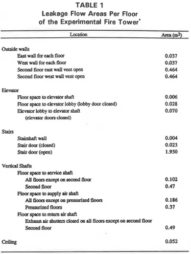
The experimental tower contains all the shafts and other features necessary to simulate air and smoke movement patterns of a typical multi-story building with a center core, including the elevator, stair, smoke exhaust, service, supply, and return-air shafts. All joints in the walls of the reinforced concrete structure are sealed to minimize uncontrolled air leakages. The exterior walls and walls of the vertical shafts are provided with variable openings that can be set to provide desired leakage areas of typical buildings. The leakage areas of the tower were set to simulate those of a building with average airtightness and a floor area of 904 m2, or seven times that of the floor area of the experimental fire tower. The values of leakage areas for the tower given in Table 1 were chosen from measure- ments of multi-story buildings conducted by Shaw et al. (1973) and Tamura and Shaw (1976).
Two propane gas burner sets, each capable of produc- ing heat at an output of 2.5 mW, are located on the second floor. Outside wall vents in the east and west walls of the second floor, each with an area of 0.464 m2, can be opened remotely during a fire test to simulate broken windows.
A separate structure, adjacent to the tower, houses the air moving and heating plant. The air ducts run under- ground through a short tunnel to the bottom of the experi- mental fire tower. One system handles the main air supply and heating load and the other supplies outside air, either to the experimental stair and elevator shafts or to vestibules located between the entrances to these shafts and the bum
14.6 m I_ 6.5 rn Service tower
time^
tower Elevator 1 -1 Building suwly 2 Buildina return 1 exhaust3 Srokerokeshaft 4 Elevator l stair lobby supply
:
%;:PL,
7 Serviceshaft
Figure 1 Floor plan of experimental fire tower.
TABLE 1
Leakage Flow Areas Per Floor
of the Experimental Fire Tower'
-rial A m (mz)
Ourddewalls
Eaa wan for uch floor Wcstarallforeadlfloor
SecoDdtlooresstwPllventopen
Second floor west wall venr o p a Eievaur
moorspace toe leva tors^ 0.006
Floor space to elevator lobby (Lobby door closed) 0.028
EievatorLobbytoeleMurshaft 0.070
(elevamrdoorscbsad)
Stairs
Stairshaftwall
Stair door (dosed)
Stair door (open)
. B & m m u s u r e m e n r r i a d u l b u i l d i n g s ~ d ~ ~ t h e d r l u h g e ~ o f a
building with a floor uea of 904 m*
area on each floor. An exhaust fan located on the roof can exhaust any floor to the outdoors through the return air shaft.
Temperatures are measured at 10 different locations on each floor using chromel-alumel thermocouples. Pressure differences across the various walls are measured using 18 static pressure taps mounted flush with the walls on each floor. All pressure lines are connected to a 24-port pressure switch equipped with a diaphragm-type magnetic reluctance pressure transducer and located on the same floor in the service area. Carbon dioxide concentrations are measured at six locations on each floo; in the shafts, lobbies, com- dors, and bum area by copper sampling tubes connected to a 12-port sampling switch unit with a nondispersive infrared gas analyzer. All measuring devices are controlled and monitored by a computer-based data acquisition and control system.
DESCRIPTION OF TEST SMOKE CONTROL SYSTEMS
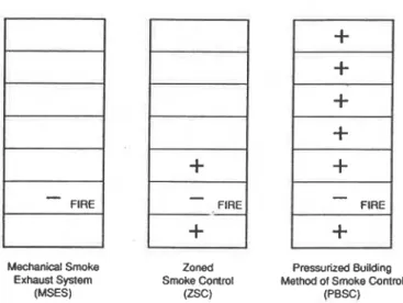
The three smoke control systems (MSES, ZSC, and PBSC) are schematically illustrated in Figure 2. All systems involved mechanical venting of the second floor, which has the propane gas burners used to generate test fire tempera-
-
FIREI
Mechanical Smoke Zoned Pressurized Building Exhaust System Smoke Control Method of Smoke ControlI
--
(MSES) (zsc) (PBSC)Figure 2 Description of test smoke control systems. tures. With the exhaust air inlet shutters of the return air shaft closed on all floors except the one on the second floor, "smoke" on this floor was exhausted through the return air shaft and out at the rooftop through an exhaust fan having a capacity of 9 m3/s at 125 Pa. The exhaust rate was adjusted to depressurize the fire floor to produce a pressure difference of 25 Pa across the stair door. This also resulted in similar pressure differences across the walls of the elevator shaft. The pressure difference of 25 Pa was intended to prevent smoke spread caused by the buoyancy force of fire. Where the floors were pressurized, the outdoor air supply rate (fan capacity of 14 m3/s at 600 Pa) was adjusted before operating the exhaust fan to produce floor pressurization of 25 Pa with reference to outside. For all smoke control systems, the supply air shutter on the second floor, which was not pressurized, was kept closed. Table 2 gives the supply air and exhaust air rates for the three systems. The exhaust air rate for MSES of 4.42 m3/s represents an air change rate of about five, based on the floor volume simulating a floor area of 904 m2 referred to previously. The air change rate of five is within the range of those measured in several multi-story buildings (Tamura and Shaw 1978). The exhaust rate required to produce a negative pressure of 25 Pa decreased as the supply air rate for floor pressurization was increased. TEST PROCEDURE
Initially, each smoke control system was tested under nonfire conditions with all stair doors closed. This was followed by opening stair doors on the fire floor, the first floor (exit to outdoors), and the one above the fire floor. These tests were conducted first with the exterior wall vents on the second floor closed and, secondly, with them open. Pressure differences throughout the fire tower were mea- sured and, for each test condition with the stair door open on the second floor, the average air velocity at this opening was obtained by conducting a 21-point hot wire anemometer
TABLE 2
Description of Smoke Control Systems Des~@tioa of Smoke Central Systems
No Supply Air for P m w h t i o a Semnd Floor Exhaust
2 5 P a ~ s t a i t d o o r
Exha- Rate
-
4.42 11131sSupply Air Rare oa Floor 1
-
1.27 m3ls F1oor3- 1.21 11131sTotal 248 m31s
Buildiog F'mdmi011- 25 Pa (ref presane id&) Supply Air to Floors 1.3
-
10Total Outside Supply Air Rate - 4.90 11131s Secoad Floor Exhaust
25 srair door with b&liq p z d m i o n (ref pressure fire floor) Exbaust Rate
-
323 11131straverse. The duration of each test was at least 15 minutes. The nonfire tests were followed by fire tests conducted under the following conditions:
At a fire temperature of 450°C and with the exterior wall vents on the second floor closed, the door-opening sequence mentioned previously was followed. When a smoke backflow at the stair door opening on the second floor was observed, the stair door was gradually closed until backflow was prevented and the door angle noted. At a fire temperature of 650°C and with exterior wall vents open (simulating broken windows), a test proce- dure similar to the one for the 450°C test was fol- lowed.
Tests were also conducted to determine the perfor- mance of the smoke exhaust system with the damper on the fire floor open but with dampers on a few other floors open as well. All tests were conducted with a wind speed of less than 20 Km/h to minimize the effect of wind on building pressures.
RESULTS AND DISCUSSIONS Nonfire Condition
The airflow and pressure difference patterns for the three systems are shown in Figures 3, 4, and 5. For all
STAIRS ELEVATOR STAIRS ELEVATOR
Mechanical Exhaust 4.42 ni3ls
Numbers are pressure differences in Pa (reference pressure-floor space)
Figure 3 Airflow and pressure dtflerence patterm caused by mechanical smoke exhaust system (MSES)-nonfire. STAIRS ELEVATOR Numbers are pressure differences in Pa (reference pressure-floor space)
+
Mechanical air supply 4.90 +Is-
Mechanical exhaust -3.23 +ISFigure 5 Airjlow pressure dlrerence patferns caused by
.pressurized building method of smoke control (PBSC)-nonfire.
Numbers are pressure differences in Pa (reference pressure-floor space)
+
Mechanical air supply 1.27 m3/s (floor 1) 1.21 m3/s (floor 2)-
Mechanical exhaust -3.73 m3/sfigure 4 Aitjlow and pressure dtrerence paltern
caused by zoned smoke control (ZSC)-non- fire.
three systems, the direction of airflow is into the fire floor from stairs, elevator, and service (not shown) shafts, from floors above and below, and from the outdoors. For MSES and PBSC, air flowed from the floor spaces into stair and elevator shafts and out from them into the floor space of the second floor. For ZSC, the direction of flow was from the stair and elevator shaft into floor spaces, except on the first and third pressurized floors, where the direction of flow was from the floor spaces into the stairshaft to pressurize the stairshaft. Also for the ZSC, the pressure differences across the floor and ceiling constructions of the second floor were about double those of MSES and PBSC.
For MSES, the entire building, along with the second floor, was depressurized with pressure differences across the outside walls of 19 to 26 Pa, except for the second floor, which were about double these values. For ZSC, except for floors 1 and 3, which were pressurized, the remainder of the floors were depressurized but much less than for MSES. The pressure differences across the outside walls on floors 1 and 3 were about 6 to 7 Pa. For PBSC with an initial pressuhzation of 25 Pa with respect to outdoor pressures, the pressure difference across the outside walls was reduced to 0 on the first floor and to 10 Pa on the tenth floor when the second floor was exhausted to produce a pressure difference across the stair door of 25 Pa.
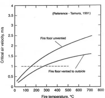
Table 3 gives the average air velocities at the open stair door on the second floor during nonfire tests with the second floor outside wall vents closed. When the stair door on the second floor was opened, the air velocities at the stair door opening for the three systems were less than 1 mls, the value specified in some building codes to prevent smoke backflow at this opening. The air velocities through open doorways required to prevent smoke backflow for various fire temperatures are given in Figure 6 (Tamura
1991).
The flow of air into the second floor through the open stair door resulted in an increase in pressures on the second floor, which reduced the pressure difference across the e l e vator shaft from 25 Pa to about 15 Pa for the three systems. Air velocities at the stair door on the second floor increased when additional stair doors were opened, accompanied by a further reduction in the pressure difference across the elevator shaft walls. These were more than 1 mls when the stair doors of floors 2 and 3 were opened and more than 2 m/s when the stair doors of floors 2 and 1 were opened and when stair doors on floors 1, 2, and 3 were opened.
Table 3 also lists cases with the outside wall vents on the second floor open during which the air velocities were much lower compared to those with the outside wall vents closed.
TABLE 3
Comparison of Air Velocity at Open Stair Door and Pressure Difference Across Elevator Door on the Second Floor-Nonfire Tests, Summer Condition
0 0 100 200 300 400 500 600 700 800 Fire temperature, "C I I I I I I I (Reference
-
Tarnura. 1991-
-
-
-
-
-
Fire floor unvented
-
-
Fire floor vented to outside
Figure 6 Critical air velocity vs. fire temperature.
Fire Conditions
The results of fire tests (450°C with outside wall vents closed and 650°C with outside wall vents open) with all stair doors closed indicated that the three smoke control systems maintained positive pressurization around the fire floor to confine smoke to this floor while maintaining the remainder of the building smoke free. This was essentially the case for the zoned smoke control system tested by Klote (1990) with a wood crib fire in a seven-story building.
The results of the fire tests for open stair doors, given in Table 4, indicate that, with a fire temperature of 450°C and the outside wall vents on the second floor closed, smoke backflow occurred when the stair door was opened on the second floor. Smoke backflow also occurred when the stair doors were opened on the second and third floors. Smoke backflow was prevented when the open stair door angle was reduced from 90" to 10" for MSES, to 13" for ZSC, and to 16" for PBSC with only the stair door on the second floor open. When the stair door on the third floor was also opened, the door angles required to prevent smoke backflow were 14" for MSES, 48" for ZSC, and 56" for PBSC.
When stair doors were opened on floors 2, 1, and 3, smoke backflow was prevented for MSES and ZSC. The data are missing for PBSC, but presumably no smoke backflow occurred for this system either, as the door angle to prevent smoke backflow with stair doors open on floors 2 and 1 was 76". However, with an increase in the flow of air through the stair door opening, the pressures in the fire floor increased to reverse the pressure difference across the elevator shaft wall, causing smoke to flow from the fire floor into the elevator shaft for MSES and ZSC. With MSES for cases with the stair doors open on floors 1 anti
TABLE 4
Comparison of Smoke Backflow at Open Stair Door and Door Open Angle Required to Prevent Smoke
Backflow -Fire Tests, Summer Condition'
* No Smoke. Backflow
-
NSB Smoke m w - SB Door Angk lo Revent Smoke Backflow - e)-.
Fue 450T. Outside Wall vents C l d
Open Stair Doors
on Flm
2
2 . 3 2 . 1
3, and also floors 2, 1, and 3, the flow direction at the holes in the floor of floor 3 (representing floor leakage openings) was from floor 2 (the fire floor) into floor 3 and, from there, into the vertical shafts. The maximum stair temperatures recorded with only the stair door on the second floor open were 139°C for MSES, 107°C for ZSC, and 112°C for PBSC. They decreased to normal tempera- tures at floor 5. Stair temperatures were much lower when additional stair doors were opened.
With a fire temperature of 650°C and with a total exterior wall vent area of 0.93 m2 (Table 4), smoke backtlow occurred with the stair door open on floor 2 and also with doors open on floors 2 and 3 for ZSC and PBSC. No fire tests at 650°C were run for MSES. No smoke backflow occurred for PBSC when stair doors were opened on floors 1 and 2 and also on floors 1, 2, and 3, whereas with ZSC, smoke backflow occurred when stair doors on floors 1, 2, and 3 were opened. The case with open stair doors on floors 1 and 2 was not run. It is likely that smoke backflow would have occurred for this case as well. For both low- and high-temperature fire tests, pressure differ- ences across the walls of the elevator shaft were more favorable in preventing smoke flow into this shaft for PBSC than for ZSC.
Table 5 shows the smoke concentration patterns with open stair doors on floors 1 and 2 for MSES and floors 2 and 3 for ZSC and PBSC and for a fire temperature of 450°C and with the exterior wall vents closed. From the smoke obscuration viewpoint, an area is assumed to be
f ABLE 5
Smoke Concentration Patterns with Open Stair Doors-Fire Tests, Summer Condition
-
Fire 650T. Outdde wauvenrsopen OpenStairDoors 1 on Floor:-
SB (139 2 3 SB (460) 2. I NSB 2 l . 3 NSB Building (PBSC) SB (167 SBmob
SBm-7
-
Mechanical Zone Smoke Exhaust h k 0 1 (MSFS)
Notes:
Smoke. Wty- % of that in the bum area of the m a d floor Fin tempaaturc
-
4 W . ooai& wall veae on a&oad floor closedStairdoorsope.onR00rs l d 2 f o r ~ ~
Stair doors open on FINITS 2 a d 3for ZSC and PBSC
SB (roo) SB (147
NSB
reasonably safe if it is not contaminated to an extent greater than 1 % of that in the vicinity of the bum area (McGuire et al. 1970). The concentration of CO,, as one combustion product, can be considered as a surrogate indicator of smoke and is expressed as a percentage of the concentration
Floor
2
(139 SB (489
-
of CO, in the burn area of the second floor. For MSES, stairshafts and several floor spaces were contaminated with smoke (with concentrations above 1 %), whereas only the stairshaft was contaminated for ZSC and the stairshaft and the floor space of the third floor were contaminated for PBSC.
When stair doors were opened on floors 1, 2, and 3, smoke concentrations were between 1 % and 2 % on the floor spaces.of floors 3, 4, 8, and 9 for
ZSC
and between 3 % and 18% for MSES. The smoke concentration pattern remained the same for PBSC when the stair doors were opened on floors 2, 3, and 5.Tests conducted at the same fire temperatures for combined mechanical venting and stair pressurization systems (Tamura 1990) kept the stairshaft free of smoke with up to four open stair doors, although the remainder of the tower was contaminated with smoke. In general, to cope with the adverse effect of opening doors, which can disrupt the effective operation of most smoke control systems, the fire temperatures and hence fire pressures need to be reduced by installing fire suppression systems. As well, the area of stair door opening should be reduced by installing vestibules to stair door access.
ZoneContml
CSC) Smoke conc.. % SIak Wev Moor
1 0 8 0 1 2 0 0 0 0 0 8 1 6 0 7 6 0 0 0 0 0 6 9 0 6 5 0 0 0 0 0 3 1 7 0 1 6 4 0 0 2 0 2 3 0 100 1 0 0 1 0 0 0 0 0 0 . Smoke Exhaust (MSES) Smoke wnc.. % Stair Elm Floor
5 0 100
NSB NSB
The Effect of Open Smoke Dampers to the Exhaust Shaft on Floors Other than the Fire Floor
P m s u h l Building ( P B X ) Smoke conc.. 8 Stair EIev Flwr
3 0 100
Mechanical exhaust of the fire floor was common to all three systems tested. The exhaust system consisted of a vertical shaft with a closed damper in the wall of the shaft on each floor and a fan on top of the shaft to exhaust above the roof to the outdoors. In the event of a fire, only the
Smoke dampers open on floors:
I
L Pressure difference across-
stair doorI
Number of smoke dampersV) 2 E L -O 0
-
..-
2
0 0 Q) V) C a, Q)'-
m L-
V) 3 ld c X WFigure 7 Effect of open smoke dampers on exhaust rate and pressure direrence across stair door on second floor.
damper on the fire floor is supposed to be opened to exhaust to the outside. The rate of exhaust can be seriously affected if dampers on floors other than the fire floor are also opened.
To investigate this, a nonfire test was conducted with an exhaust shaft (damper area of 0.49 mZ) in the experi- mental fire tower with the second floor as the fire floor.
1
Initially, a damper on the second floor was opened and this floor was exhausted at 4.72 m3/s to produce a pressuredifference across the stair door of 44 Pa. Dampers on floors
I
4, 6, and 8 were then opened in succession while the exhaust rates and the pressure differences across the stair door were recorded.The results of the test are shown in Figure 7. When a damper on the fourth floor was opened, the exhaust rate was reduced by 3 1 % and the pressure difference across the stair door by 68%. When, in addition, the damper on the sixth floor was opened, the reductions were 49% for the exhaust rate and 91 % for the pressure difference; with the damper on the eighth floor also opened, they were 60 % and about 100 %
,
respectively.When a building is pressurized and the mechanical exhaust system is malfunctioning, as when dampers are inadvertently opened or left open, the pressures on the fire floor would be higher than outside. In such a case, when a stair door on the fire floor and an exit door on the ground floor are open, smoke is likely to flow into the stairshaft and down and out through the exit door to the outdoors to hamper evacuation.
As seen in Figure 7, failure of even one damper to close can greatly reduce the exhaust rate on the fire floor and the required pressure difference across the stair door.
Hence, some means of monitoring the opening and closing of dampers at the central control station are needed during a fire, as well as for periodic maintenance checks. In this respect, a dedicated system would normally have all the smoke dampers closed and, in the event of fire, only the smoke damper on the fire floor would be opened. This would be more reliable than using a central return air system as exhaust, which would require closing all branch dampers except the one on the fire floor.
SUMMARY
The performances of the mechanical smoke exhaust system (MSES), zoned smoke control (ZSC), and pressur- ized building method of smoke control (PBSC) were evaluated under nonfire and fire conditions. The results of
the tests are as follows:
All three systems prevented smoke spread when all stair doors were closed.
For fire tests at 450°C with exterior wall vents closed and two stair doors, including the one on the fire floor, opened, the stairs and all floor spaces were contaminat- ed with smoke for MSES, only part of the stairshaft was moderately contaminated with smoke for ZSC, and only the stairshaft and floor above the fire floor were contaminated with smoke for PBSC. When one addi- tional door was opened, a number of floor spaces were moderately contaminated with smoke for ZSC, whereas the extent of contamination remained the same for PBSC.
It was shown that, even when one extraneous smoke damper was opened, the exhaust rate of the fire floor and the favorable pressure difference across the stair door were decreased drastically.
When stair doors are opened, smoke contamination of the stairshaft and other areas of a building can be expected. This was also the case for stair pressurization systems (Tamura 1992). Sprinkler systems would reduce fire pressures and, hence, reduce the amount of smoke back- flow. Lobbies to stairshafts would minimize the number of stair door openings by permitting either the stair door or the vestibule door to be closed while entering or leaving the stairshaft. Further tests of these smoke control systems under sprinklered fire conditions are required.
ACKNOWLEDGMENTS
The authors gratefully acknowledge the contributions of D.W. Carpenter and V.A. Fortington in carrying out tests in the experimental fire tower.
REFERENCES
Klote, J.H. 1990. Fire experiments of zoned smoke control at the Plaza Hotel in Washington, D.C. ASHRAE Transactions 96(2): 399-416.
Klote, J.H., and J.W. Fothergill, Jr. 1983. Design of smoke control system for buildings. Atlanta: American Society of Heating, Refrigerating and Air-Conditioning Engineers, Inc.
McGuire, J.H., G.T. Tamura, and A.G. Wilson. 1970. Factors in controlling smoke in high buildings. ASH-
RAE
SymposiumBulletin, Fire Hazards in Buildings, San Francisco, CA.NRCC. 1990. Supplement to the National Building Code of Canada. Chapter 3, Measures for fire safety in high buildings, pp. 69-130. Ottawa: National Research Council of Canada.
Shaw, C.Y., D.M. Sander, and G.T. Tamura. 1973. Air leakage measurements of the exterior walls of tall buildings. ASHRAE Transactions 79(2): 40-48. Tamura, G.T. 1990. Fire tests of stair pressurization
systems with mechanical venting of the fire floor. ASHRAE Transactions 96(2): 384-392.
Tamura, G.T. 199 1. Determination of critical air velocities to prevent smoke backflow at a stair door opening in the fire floor. ASHRAE Transactions 97(2): 627-633. Tamura, G.T. 1992. Assessment of stair pressurization
systems for smoke control. AShRAE Transactions 98(1): 66-72.
Tamura, G.T., and C.Y. Shaw. 1976. Air leakage data for the design of elevator and stair shaft pressurization systems. ASHRAE Transactions 82(2): 179-190. Tamura, G.T., and C.Y. Shaw. 1978. Experimental studies
of mechanical venting for smoke control in tall office buildings. ASHRAE Transactions 84(1): 54-71.
Reprinted from ASHRAE TRANSACTIONS by permission of the American Society of Heating, Refrigerating and Air-Conditioning Engineers, Inc.