CHARACTERIZATION OF CARBON ANODE MATERIALS BY IMAGE ANALYSIS
Xian-Ai Huang1, Duygu Kocaefe1, Dipankar Bhattacharyay1, Yasar Kocaefe1, Brigitte Morais2
1 UQAC/AAI Research Chair on Carbon and REGAL Aluminum Research Center
University of Quebec at Chicoutimi 555 Boulevard de l'Université, Chicoutimi, QC, Canada G7H 2B1
2Aluminerie Alouette Inc., 400, Chemin de la Pointe-Noire, Sept-Îles, Québec, Canada G4R 5M9
Keywords: Wetting, microscopy, carbon anodes, characterization of carbon materials, calcined petroleum coke, coal tar pitch
Abstract
Carbon anodes are made of calcined petroleum coke, recycled carbon materials (butts and anodes), and coal tar pitch. The pitch and coke properties strongly influence the anode quality. High- quality anodes help reduce the energy consumption and environmental emissions during the electrolysis. Methods have been developed to characterize the structural aspects of green and baked anodes, coke-pitch and biocoke-pitch samples from the sessile-drop wettability tests as well as the solid particles of various pitches. These methods are based on the analysis of the images obtained by the optical and scanning electron microscopy techniques. Such data help determine the possible impact on anode quality. Biocokes could serve as alternate raw materials for the partial replacement of petroleum coke, and biocoke samples were prepared from wood by calcination at high temperatures.
The wetting of biocokes by pitch was compared with that of petroleum coke. This article presents the results of the characterization work.
Introduction
Carbon anodes used in aluminum industry consist of different carbon materials such as petroleum coke, recycled carbon materials (butts and anodes), and coal tar pitch. These exhibit different structures and forms in anodes due to different mixing conditions and heat treatments that they are subjected to during anode fabrication. The structure of coke and the interface between coke and pitch formed in the anode during baking are some of the important factors which influence the quality of baked anodes.
Many researchers have worked on the characterization of carbon material surfaces using different techniques [1-8]. Optical microscopy and scanning electron microscopy (SEM) were used to characterize the structure of different metallurgical cokes using various etchants [1, 4]. It was seen that the carbon textural constituents observed by microscopy contribute to the coke strength [1]. It was also reported that the textural composition of carbonized pitch studied using SEM can successfully explain the mechanical properties of the corresponding anode [3]. Hays et al.
[2] fabricated baked carbon electrodes using a petroleum coke and four different coal tar pitches as binder. They used SEM to differentiate coke, coke/pitch interface, and carbonized pitch in carbon anodes. They used the laboratory baked carbon anodes which were fabricated from coke particles with a narrow range of size distribution. However, they did not study the commercial carbon anodes containing highly fine coke particles.
The object of the present study is to investigate a number of cokes and carbon materials with the particle size distribution used in anode production by means of microscopic characterization methods (optical microscopy and scanning electron microscopy).
An attempt was made to compare the differences in the textures of green and baked anodes as well as pure pitch or pitch/wood mixtures before and after carbonization. The pitch/wood mixture was heat treated to produce carbonized pitch/biocoke.
In addition, wetting tests were performed by measuring the dynamic contact angles of pitch on coke beds using the sessile- drop method. The wettability of pitch on biocoke and petroleum coke particles were investigated from SEM micrographs of pitch- biocoke and pitch-petroleum coke sessile-drops; and these were correlated with the wettability test results. The applications of optical microscopy and SEM are presented for different carbon materials with the aim of identifying suitable techniques.
Experimental Calcination of biocoke
The biocoke samples received from Boisaco Inc. were calcined to 1200°C in a TGA (thermogravimetric analyzer) with induction heating at the University of Quebec at Chicoutimi (UQAC). A heating rate of 40 °C/h and a holding time of 15 min at the maximum temperature were used, which are typical values for green petroleum coke calcination. The TGA with induction heating was chosen because high heating rates required for coke calcination can be achieved in such a system. The calcination was carried out under pure nitrogen atmosphere to prevent the oxidation of carbon materials.
W
etting tests
The dynamic contact angles between pitch and biocoke as well as pitch and petroleum coke were measured using a sessile-drop experimental system. This system consists of a tube furnace (Thermolyne 21100), an Inconel tube with a pitch injection system, a graphite crucible for the coke sample, a digital video camera (B/W) (APPRO, model KC), and a secondary rotary vacuum pump (GE, Precision Vacuum Pump, Model D25).
Biocoke and petroleum coke particles were ground, and particles less than 125 µm (-125 µm) were used for the wetting tests in accordance with the findings of a previous study [9]. The particles were compacted in the sample crucible to have a smooth bed surface. A drop of pitch was formed on the coke substrate by keeping the temperature constant at 170 °C and controlling the pressure difference between the metal injection chamber and the tube furnace. The experiments were conducted under protective nitrogen atmosphere. The FTA 32 software was used to measure the contact angle from the dynamic images captured during the wetting experiments. The dynamic contact-angle data were used to assess the wettability. The coke-pitch sessile-drops were examined with an optical microscope and an SEM.
Production of green and baked anodes
Anodes were produced in the laboratory using an anode recipe similar to a typical industrial recipe. The coke and pitch were mixed at a certain temperature, and the anode paste was vibro- compacted to obtain green anodes. Then, these were baked under the conditions typically used in industry.
Investigation with the Optical Microscope and the SEM
Coal-tar pitch, green anode, baked anode, calcined biocoke-pitch, coke-pitch samples from the sessile-drop wettability tests, and carbonized pitch/biocoke mixtures were characterized using optical microscopy and SEM.
The samples were mounted into the epoxy liquid resin and polished by a Struers polisher to create a scratch free surface. The textual morphology was investigated using a Nikon Eclipse ME600 optical microscope (Nikon Inc., Melville, NY), and the images were analyzed with Optical Image Analyzer (Clemex JS- 2000). Then, the epoxy resin of polished block samples was removed to have the polished carbon samples which were subsequently mounted onto the surface of an aluminum block using an electrically conducting paste and sputter-coated with a palladium/gold layer to have electrically conductive surface. The samples were scanned using a Jeol SEM (JSM 6480LV).
Results and discussion Green and baked anodes
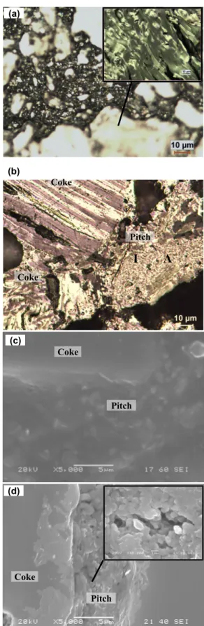
Optical microscopy images illustrating the appearance of green and baked anode surfaces at low magnification are shown in Figures 1a and 1b. Due to the different hardnesses of coke and pitch in green anodes, it is difficult to obtain a sufficiently even surface (Figure 1a). This makes the focusing on all the elements of the surface difficult at the same time while taking images with the optical microscope. It is possible to observe coke and pitch seperately. The coke particles in green anodes as well as the small particles in pitch exhibit optical anisotropy. Even at this low magnification (500x), differences in the surface morphology of green and baked anodes can be detected (Figures 1a and 1b). The surface of a baked anode (Figure 1b) shows that the pores are created in pitch during baking due to volatile release. Anisotropic cokes are present in a baked anode, and both isotropic (I in Figure 1b), and anisotropic (A in Figure 1b) structures occur in pitch after baking to high temperature.
Due to the limit of optical microscopy, the structure of pitch in green anodes can not be clearly observed with this technique. The uneven and porous nature of anode surfaces necessitates their examination using SEM (Figure 1c). The particles of pitch in green anodes can be visually identified in a SEM micrograph (Figure 1c) even after polishing the sample surface. Spherical particles of pitch were observed in the baked anode sample (Figure 1d), but there was no indication of the presence of an anisotropic structure that was seen by the optical microscopy (Figure 1b). Anisotropic or isotropic structures of coke in both green and baked anodes could not be seen clearly by SEM for such polished surfaces. It is possible that the high magnification and small field of view of SEM micrographs made it difficult to see the anisotropic surfaces.
Figure 1 Optical microscopy images of (a) green anode, (b) baked anode; and SEM images of (c) green anode, (d) baked anode
I
Coke (a)
A
Pitch Coke
(b)
Pitch Coke
(c)
Coke
Pitch (d)
It was reported that atomic oxygen and chromic acid solutions can be used as etchants to help obtain images of metallurgical coke and carbon structures [4]. As carbonized pitch is more reactive to oxidizing agents compared to calcined petroleum coke, selective oxidation of pitch surface can be done by the use of etchants. The change in the surface texture of carbonized pitch by etching helps differentiate pitch from the coke particles. The etching method may provide more structural information of the particles and pitch in both green and baked anodes. This will be further studied. In addition, micro-crack formation is not observed between coke and pitch in anode samples even after baking, which indicates the good bonding between them for the samples studied. Furthermore, interaction zones at the interface of calcined coke and carbonized pitch show possible reaction. The possibility of the presence of reaction products has been assumed based on the difference in texture and the brightness of the surface at the interface compared to those of the coke surface.
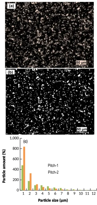
Pitch and pitch/wood mixture before and after carbonization The pitch samples were prepared in epoxy resin and polished, and then their optical microscopy images were taken in such a way that the background appeared dark. Figure 2a shows the solid particles in pitch. Then, the image was binarized as shown in Figure 2b where the solid particles appear white and the rest of pitch appears black. The solid particles in the binary images are separated with clear boundaries. The particles sizes (maximum length) were determined using the image analysis software of Clemex. Figure 2c shows the comparison of the solid particle size distribution in two different pitches using the image analysis technique. This technique may help relate the pitch properties to different anode properties.
The SEM images in Figures 3a and 3b illustrate the appearance of the solid particles of pitch. The polishing process has removed the softer components of pitch preferentially leaving the harder solid particles (see Figures 3a and 3b). The micrographs show that spherical solid particles of less than 1 µm in diameter are present in pitch. It was reported that the mesophase spheres are 10-20 μm in size [2]. Thus, the SEM analysis results indicate that the pitch in this study does not contain mesophase. An SEM image illustrating the appearance of agglomerated submicron particles is shown in Figure 3b. These particles appear to be carbon black according to their characteristics [2].
The carbonized pitch was obtained by baking the pure coal tar pitch using the same heating rate used to bake the anode. The polished surface of carbonized pitch has been examined by both optical microscope and SEM (Figure 4 a -c).
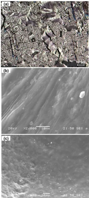
It can be observed from Figure 4a that the appearance of the carbonized pitch exhibit similar surface textures found in metallurgical cokes [2]. Hays et al. [2] mentioned that the texture in carbon particles can be characterized based on lamellar, intermediate, and granular components. The carbonized pitch in the current work contains only two components, namely, lamellar (position A) and granular (position I). The granular component is present in greater proportion than the lamellar one. The appearance of the two components in the carbonized pitch is clearly visible from the SEM images in Figures 4 b and c, which shows the details of the polished carbonized pitch surface.
The nature of lamellar components on the polished surface can be easily identified when the pure pitch is baked as seen in SEM images (Figure 4b), but not in pitch-coke of anodes. The granular components in carbonized pure pitch appear as small pits with small spheres. Micron-size particles are visible in the granular area as shown in Figure 4c. Corresponding views visible in baked anode surfaces are given in Figure 1d as small spheres. The appearance of pitch in baked anodes is quite different from that of carbonized pure pitch in SEM images. The optical microscopy images of pitch in baked anodes and carbonized pitch obtained from pure pitch show a similar structure (see Figures 1b and 4a).
1 2 3 4 5 6 7 8 9 10 11 12 0
200 400 600 800 1,000
r
Pa tcle size (µm)
rPatcle amount (%)
Figure 2(a) Optical microscopy image, (b) Binary image, (c) Solid particle size distribution in two different pitches This might be due to the high magnification of SEM which focuses on a small region in an image which cannot contain all the structural components. The presence of a relatively small amount
(a)
(b)
Pitch-1 Pitch-2 (c)
of pitch-coke in baked anodes makes the observation of all its structural components difficult using image analysis techniques, which might be another reason for the difference between optical microscopy and SEM analysis.
Pitch/wood mixtures were carbonized under similar conditions as the anode baking process to produce carbonized pitch/biocoke.
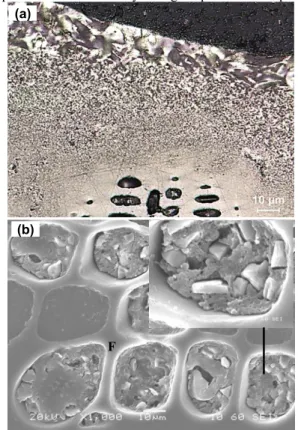
Optical microscopy and SEM images illustrating the appearance of carbonized pitch/biocoke are shown in Figure 5. The carbonized pitch/biocoke in Figure 5a consists of lamellar structure close to the pore surface where the volatiles are passing and granular structure close to the matrix of carbonized biocoke.
The matrix of biocoke shows cell walls that are usually present in wood. This phenomenon indicates that the presence of cell walls stops the expansion of anisotropic structure during carbonization.
The pitch can easily enter the cell lumen of biocoke and mix with small biocoke particles present in the cell lumen, which helps form the granular component of pitch during heating. The appearance of the cell wall of the biocoke in the SEM image of Figure 5b is indicative of the structural unit present, namely, flat component (Position F in Figure 5b) [3].
Figure 3 SEM images of solid components of coal tar pitch:
(a) solid particles, (b) carbon black particles Pitch-biocoke and pitch-petroleum coke sessile-drops
The information on the wettability of coke by pitch is useful in understanding the interaction mechanism between coke and pitch and exploiting the possibility of using biocoke as a raw material for anodes. During this study, the dynamic contact angle (wettability) of a biocoke/pitch sample was measured, and the results were compared with those of a calcined petroleum coke/pitch sample. Figure 6 presents the dynamic contact angle of
coke/pitch system as a function of time for a biocoke and a petroleum coke. As it can be seen in this figure, the contact angles of biocoke were lower than those of petroleum coke at all times.
This shows that the biocoke was wetted better than the petroleum coke by pitch used in this study. Most of the pitch penetrated into the biocoke within 400 s while there is still pitch present on the petroleum coke surface even at 1500 s.
The differences in coke structure and particle shape can cause differences in the wettability behavior. In order to investigate the influence of biocoke structure on pitch/biocoke interactions, the relevant microstructures of pitch/biocoke interfaces were meticulously examined. The interface of pitch and coke was studied by vertically cutting (see Figure 7) the sessile-drops obtained from the contact angle tests and analyzing them with the optical microscope and SEM (Figure 8).
Figure 4 Optical microscope micrograph showing (a) general view (A: anisotropic structure, I: isotropic sturcture); and SEM images (a)
(b)
A I
(a)
(b)
(c)
showing (b) lamellar component, (c) granular component in carbonized pure pitch
The biocoke and petroleum coke particles as well as pitch can be easily identified from both the optical microscopy (Figures 8a and 8b) and SEM images (Figures 8c and 8d). The appearance in the interface shows that biocoke and petroleum coke have different particle shapes (Figures 8a and b), and the structural factors play an important role in wettability during the penetration of pitch.
Figure 5 (a) Optical microscopy and (b) SEM images of carbonized pitch/biocoke
0 400 800 1200 1600
0 20 40 60 80 100
Petroleum coke/ Pitch-1 Biocoke / Pitch-1
Time (s)
Contact Angle (θ°)
Figure 6 Comparison of the dynamic contact angles of pitch on petroleum coke and biocoke beds
Figure 7 (a) Image of a sessile-drop, (b) the schematic representation of a sample taken from the sessile-drop cross-
section to study the coke-pitch interface (a)
F (b)
Pitch drop
Pitch in coke bed
Coke bed (a) (b)
(a)
Biocoke Pitch
Coke Pitch
(b)
Biocoke
Pitch (c)
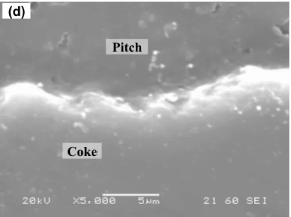
Figure 8 Optical microscopy images of (a) pitch/biocoke and (b) pitch/petroleum coke; SEM images of (c) pitch/biocoke and
(d) pitch/petroleum coke
It can be seen from Figure 8 that biocokes are more anisotropic than isotropic, and their porosities are higher than those of petroleum coke. The porous structure of biocoke contributes to higher wettability by pitch where pitch component can penetrate into the pores as shown in Figure 8c. Figure 8d shows a section of the petroleum coke-pitch interface. The difference in brightness close to the interface of pitch and biocoke suggests the possible presence of reaction products. Figure 8d does not show the presence of pores which are apparent in Figure 8c.
Conclusions
The optical microscope and SEM can be used to characterize the structure of different carbon materials such as green and baked anodes, coke-pitch and biocoke-pitch samples from the sessile- drop wettability tests as well as pure pitches and pitch/wood mixtures before and after carbonization. The two techniques have their own advantages for different carbon materials, and they can be used as complementary techniques for a better characterization of a given sample. Furthermore, their combination contributes to the understanding of the internal structure within carbon materials and at the interface between pitch and biocoke or petroleum coke, consequently giving an insight into the mechanism of wettability.
Acknowledgements
The technical and financial support of Aluminerie Alouette Inc. as well as the financial support of the National Science and Engineering Research Council of Canada (NSERC), Développement économique Sept-Îles, the University of Quebec at Chicoutimi (UQAC), and the Foundation of the University of Quebec at Chicoutimi (FUQAC) are greatly appreciated. Part of the research presented in this paper was financed by the Fonds de recherche du Québec - Nature et technologies by the intermediary of the Aluminium Research Centre – REGAL.
References
[1] D. Hays, J.W. Patrick, A. Walker, A scanning electron microscope study of fractured and etched metallurgical coke surfaces, Fuel, 61 (1982) 232-236.
[2] D. Hays, J.W. Patrick, A. Walker, SEM study of binder coke in electrode carbon, Fuel, 62 (1983) 946-952.
[3] D. Hays, J.W. Patrick, A. Walker, SEM characterization of cokes and carbons, Fuel, 62 (1983) 1079-1083.
[4] H. Marsh, M. Forrest, L.A. Pacheco, Structure in metallurgical cokes and carbons as studied by etching with atomic oxygen and chromic acid, Fuel, 60 (1981) 423-428.
[5] A. Méndez, R. Santamaría, M. Granda, T. Morgan, A.A.
Herod, R. Kandiyoti, R. Menéndez, Influence of granular carbons on pitch properties, Fuel, 82 (2003) 1241-1250.
[6] J.W. Patrick, M.J. Reynolds, F.H. Shaw, Development of optical anisotropy in vitrains during carbonization, Fuel, 52 (1973) 198-204.
[7] J.W. Patrick, F.H. Shaw, R.R. Willmers, Microscopic examination of polished coke surfaces etched by ion bombardment, Fuel, 56 (1977) 81-88.
[8] J.L. White, The formation of microstructure in graphitizable materials, Progress in Solid State Chemistry, 9 (1975) 59-104.
[9] A. Sarkar, D. Kocaefe, Y. Kocaefe, D. Sarkar, D.
Bhattacharyay, B. Morais, J. Chabot, Coke-pitch interactions during anode preparation, Fuel, 117 (2014) 598-607.
Pitch
Coke (d)