HAL Id: tel-01989197
https://tel.archives-ouvertes.fr/tel-01989197
Submitted on 22 Jan 2019HAL is a multi-disciplinary open access archive for the deposit and dissemination of sci-entific research documents, whether they are pub-lished or not. The documents may come from teaching and research institutions in France or abroad, or from public or private research centers.
L’archive ouverte pluridisciplinaire HAL, est destinée au dépôt et à la diffusion de documents scientifiques de niveau recherche, publiés ou non, émanant des établissements d’enseignement et de recherche français ou étrangers, des laboratoires publics ou privés.
optimization and integration of bio-inspired anodesin a
platinum-free pemfc
Nathan Coutard
To cite this version:
Nathan Coutard. optimization and integration of bio-inspired anodesin a platinum-free pemfc. Inor-ganic chemistry. Université Grenoble Alpes, 2018. English. �NNT : 2018GREAV021�. �tel-01989197�
THÈSE
Pour obtenir le grade de
DOCTEUR DE L'UNIVERSITÉ GRENOBLE ALPES
Spécialité : Chimie inorganique et bio-inorganiqueArrêté ministériel : 7 août 2006
Présentée par
Nathan Coutard
Thèse dirigée par Vincent Artero
préparée au sein du Laboratoire de Chimie et Biologie des Métaux dans l'École Doctorale de Chimie et Sciences du Vivant
Optimisation et intégration
d'anodes bio-inspirées dans
une pile à combustible sans
platine
Optimization and integration of
bio-inspired anodes in a
platinum-free fuel cell
Thèse soutenue publiquement le 28 septembre 2018 devant le jury composé de :
Mme. Elena Savinova
Professeure, Université de Strasbourg, Rapportrice Mme. Kylie Vincent
Professeure, University of Oxford, Rapportrice Mme. Carole Duboc
Directrice de recherche, Université Grenoble Alpes, Présidente du jury M. Frédéric Jaouen
Chargé de recherche, Université de Montpellier, Examinateur M. Vincent Artero
Directeur de recherche, CEA, Directeur de thèse Mme. Pascale Chenevier
3
Voici l’heure des remerciements qui arrivent non par ordre d’importance ni même suivant une quelconque convention savamment préétablie, mais dans l’ordre auquel j’ai pensé à vous, ce qui n’est sans doute pas aussi innocent que ce que l’on pourrait souhaiter. J’ai quand même gardé Vincent pour la fin et le suspens… A ma famille, que nous vîmes cinq mille en arrivant dans la salle de soutenance, je vous dirai peut-être ce que je pense ce soir en mangeant de l’aligot. Je vous aime tous. Marianne, heureusement que t’étais là parce que putain sans une amie trois ans ça aurait été long, dur, chiant et terriblement sobre. Merci pour tout ce bonheur. Henry David Thoreau dit qu’il suffit grosso modo de 4 trucs sur terre : la bouffe, le feu, les vêtements et une maison. Alors jsuis pas mal d’accord avec lui, mais je pense qu’il passe à côté de l’essentiel. Et l’essentiel, c’est les occupants de la maison parce qu’une baraque vide c’est déprimant. Thomas, Nico, Marie, Cécile et Arthur : on a partagé tellement plus qu’un loyer. Des bières principalement. Aux p’tits copains dits « de la pause-café » : Sarah, Steve, Chloé (petit ange parti trop tôt) et Lulu : un burne-out c’est quoi déjà ? Merci. Merci d’avoir été un public patient et attentif, merci pour la bouffée d’air frais qui rend possible le travail acharné des heures vespérales, inhérent à la recherche presque publique et merci d’éteindre la lumière en partant le vendredi. Jojo, merci pour les conseils rando et les câbles, pétés tout en douceur, allant en s’intensifiant vers la fin de nos contrats respectifs. Un jour on ira marcher ensemble, peut-être ? Pour des déjeuners toujours agréables passés à parler dans 14 langues simultanément, je tiens à remercier Jaione et Marila. J’espère que vous allez survivre à votre séparation imminente. Olivier, Steph Torelli et Lulu merci pour les conseils bricolage et les bons plans de fournisseurs, ça fait plaisir de causer avec des gens qui font des choses. Caroline, merci pour les conseils vestimentaires et capillaires mais jsuis majeur et vacciné et je fais ce que je veux avec mon ptit corps. A tout SolHyCat, merci pour un labo agréable et pour des discussions scientifiques de haut vol. Merci à Jenni et Adina pour toute l’aide logistique et de rendre tout facile tous les jours chez SolHyCat. C’est fou à quel point ça change la vie quand un labo tourne comme une machine bien huilée. Murielle, désolé de pas aimer la mousse au chocolat mais merci d’avoir essayé, merci pour les discussions scientifiques de haut vol. Matthieu, bravo, presque 3 ans dans le même bureau que moi c’est pas tout le monde qui survit pour en parler. Et tu n’as eu besoin de déménager qu’une fois ! Désolé pour les chants de Noël en russe et les guirlandes épileptiques. Prends soin des plantes quand je serai parti. Toutes les plantes. Pas seulement celle que tu aimes. Ne laisse pas mourir mon sapin moche. Bertrand, tu me rappelles Georges politiquement. Tim, thanks for brexit. Was about time. Nick, thanks for major pop culture enhancing discussions. Stéphane Ménage, futur ex-directeur du meilleur LCBM, mort à l’intérieur durant l’exercice de ses fonctions, merci pour votre sacrifice vous ne serez pas oublié. Roger, de la part des presque 80 personnes non concernées mais contactées par courrier électronique, tout le monde s’en fout de qui a pissé dans une centrifugeuse au bâtiment K. Nico et Nico, merci pour le flambeau, j’ai essayé d’être en même temps parisien, impertinent, grand et niais, de mauvaise foi quand ça m’arrange, électrochimiste, spécialiste des machins rugueux qui marchent pas et des blagues de mauvais goût et surtout un mec sympa. J’ai fait de mon mieux et j’espère que ça passe, si ça passe pas c’est le même tarif de toute façon. Juju, merci pour les duos lyriques et les conseils avisés concernant à peu près tout. Et la culture footballistique. Parce qu’une famille normale selon Christine Boutin c’est un papa et une maman, Pascale tu fus tout ce que Vincent ne pouvait pas être. Intelligente, brillante, disponible, intéressée et intéressante. Si je peux me permettre un conseil maintenant que je suis docteur ? Continue à t’intéresser à tout, tout le temps. C’est malheureusement pas valorisé par les hautes sphères de financement de la recherche publique, mais c’est tellement nécessaire. Vincent, merci de m’avoir fait confiance. Je partais pas gagnant avec ma photo de profil skype mais j’espère avoir été à la hauteur. Jsuis assez content d’avoir réussi à te faire faire des trucs que tu ne comprenais pas complètement, parce que dieu sait que c’est rare les choses que tu ne comprends pas. Merci d’avoir été tout ce qu’on est en droit d’attendre d’un directeur de thèse, et je ne ferai pas d’inventaire car je n’ai pas la plume de Pérec ou Prévert, mais aussi d’avoir été beaucoup de ce qu’on peut attendre d’un ami. J’ai vu autour de moi des doctorants pas contents, je suis tombé au mieux. Ce mélange en proportions toujours bien dosées d’encadrement et de liberté qui fait les grands mentors. Tu serais parfait si t’étais pas en marche. Merci pour trois ans de science et plus car affinités. A tous les autres, désolé de vous avoir oubliés mais merci, merci mille fois merci de ne pas m’en tenir rigueur, c’est vraiment sympa.
4
"Que diable allait-il faire dans cette galère ?" Molière, Les fourberies de Scapin, II, 7
"I'm being quoted to introduce something, but I have no idea what it is and certainly don't endorse it."
5
6
Abbreviations ... 10
Preamble ... 12
Introduction ... 14
1. Hydrogen fuel cells ... 15
a. Anion-exchange membrane fuel cells (AEMFCs) ... 16
b. Proton-exchange membrane fuel cells (PEMFCs) ... 16
2. Activity markers of hydrogen interconversion catalysts ... 17
a. Equilibrium potential and overpotential ... 18
b. Turnover frequency ... 18
c. Site density and loading ... 19
d. Catalytic bias ... 19
e. Stability ... 20
f. Tafel plots ... 20
3. Pt catalysts ... 21
4. Alternative catalysts ... 22
5. Inspiration from nature ... 23
a. Hydrogenase enzymes ... 23
b. Bio-mimicry and bio-inspiration ... 25
c. Bio-inspired molecular catalysts ... 27
6. Grafting of molecular catalysts onto electrode materials ... 28
a. Physical adsorption: entrapment in a polymeric layer ... 29
b. Diazonium reduction of anchoring moieties ... 30
c. π-stacking interaction ... 32
7. State of the art of anodes for HOR ... 34
8. Ambitions of this work ... 36
Chapter I – Catalyst choice and effect of ionomer ... 38
7
a. Catalytic activity ... 39
b. Catalyst loading ... 41
c. Molecular structure of the active sites: XAS studies ... 43
2. Effect of ionomer on activity ... 48
a. Generalities about Nafion ... 48
b. Effect of Nafion on bio-inspired catalytic materials ... 50
c. Nafion structuration around carbon nanotubes ... 55
d. Comparison with colloidal Pt nanoparticles ... 56
3. Choice of a bio-inspired catalytic system for optimization and integration ... 58
4. Experimental section ... 59
a. Electrochemistry ... 59
b. Synthesis of DuBois ligands and complexes ... 59
c. GDL/MWNT/CyPy electrode ... 61
d. GDL/MWNT-NH2/CyEster electrode ... 62
e. GDL/MWNT-COOH/CyArg electrode ... 63
f. ULL-Pt modification of nanotubes ... 63
Chapter II – Catalytic ink formulation and deposition ... 66
1. Catalytic ink formulation ... 67
a. Previous work in the group ... 67
b. Effect of different carbon additives on catalytic activity... 68
c. Ionomer within the ink, and fullerene as a diffusion enhancing additive ... 73
d. Catalyst to support material ratio ... 76
e. Proton-exchange membrane ... 77
2. Deposition of the catalytic ink ... 80
a. Support material ... 81
b. Amount of catalytic ink ... 84
8
4. Conclusion ... 87
5. Experimental section ... 89
a. Benchmarking of carbon additives ... 89
b. Nafion ratio ... 89
c. Fullerene ratio ... 89
d. Catalyst to support material ratio ... 89
e. Nafion membrane conditioning ... 90
f. MEA assembly ... 90
g. Support material ... 90
h. Amount of catalytic ink ... 90
Chapter III – Advanced electrochemical characterization ... 92
1. Assessment of stability ... 92
2. Effect of temperature, activation energy ... 94
3. Tafel analysis ... 95
4. Electrochemical impedance spectroscopy models for catalytic activity ... 101
a. A brief introduction to EIS ... 101
b. EIS model for pure catalysis: 0 to 50 mV overpotential ... 104
c. Model for the catalytic plateau ... 109
5. Conclusion ... 112
6. Experimental section ... 113
d. CO tolerance ... 113
e. Temperature study ... 113
f. Electrochemical impedance spectroscopy ... 113
Chapter IV – Integration in PEMFCs ... 115
1. Benchmarking apparatus ... 115
2. Activity markers of a fuel cell ... 117
9 b. Power output ... 118 3. Technological considerations ... 118 a. Water management ... 118 b. Operating temperature ... 119 c. Conditioning ... 120 4. Membrane-electrode assembly ... 121 a. Anode ... 121 b. Membrane ... 121 c. Cathode ... 122
d. Assembly of the MEA ... 123
5. Performances ... 124
a. Expected power output ... 124
b. Performances of compact PEMFCs ... 125
c. Performance with liquid electrolyte junction ... 126
d. Stability over time and temperature ... 128
e. Comparison to previous results and state of the art ... 130
6. Conclusion ... 132
7. Experimental section ... 133
a. Benchmarking apparatus & electrochemical measurements ... 133
b. Membrane-electrode assembly for compact PEMFCs ... 133
c. Spray-coated compact PEMFC ... 134
d. Membrane-free compact PEMFC ... 134
e. Liquid electrolyte fuel cell ... 135
f. Stability over time and temperature of PEMFCs ... 135
g. Assessment of stability vs. temperature of DuBois complexes ... 135
General conclusion ... 137
10
Abbreviations
atm.: atmospheric BET: Brunauer-Emmett-Teller Cy: cyclohexyl CV: cyclic voltammetry DCM: dichloromethane dist.: distilled DMF: N,N-dimethylformamide DMSO: dimethylsulfoxideEDX: energy-dispersive X-ray specroscopy EIS: electrochemical impedance spectroscopy equiv.: equivalent
EXAFS: extended X-ray absorption fine structure E1/2: mid-wave potential
GCE: glassy carbon electrode GDL: gas diffusion layer Gly: glycine
HER: hydrogen evolution reaction
HEPES: 2-[4-(2-hydroxyethyl)piperazin-1-yl]ethanesulfonic acid HOR: hydrogen oxidation reaction
HRTEM: high-resolution transition electron microscopy LSV: linear sweep voltammetry
11 MeCN: acetonitrile
MES: 2-(N-morpholino)ethanesulfonic acid MWNT: multi-wall carbon nanotube
NHE: normal hydrogen electrode NMR: nuclear magnetic resonance ORR: oxygen reduction reaction
PEIS: potentiostatic electrochemical impedance spectroscopy PEM: proton-exchange membrane
PEMFC: proton-exchange membrane fuel cell PGM: platinum group metals
Ph: Phenyl
ppm: parts per million RT: room temperature
SEM: scanning electron microscopy SWNT: single-wall carbon nanotube TEM: transition electron microscopy TOF: turnover frequency
TOFmax: maximum turnover frequency
TON: turnover number
XANES: x-ray absorption near edge structure XAS: X-ray absorption spectroscopy
Constants
F: faraday constant (96485 C·mol-1) R: ideal gas constant (8.314 J·K-1·mol-1)
12
Preamble
In a never-ending, exponentially growing thirst for expansion and technological improvements originating with the first tool and snowballing since the industrial revolution, mankind seems to have placed itself in a bit of a pickle. We are going to need much more than what the exploitable universe has to offer to quench that thirst. Our global economy model, based on unending growth, is not viable with our limited natural resource and before we run out of breathable air and start worrying about much more serious problems, we will start running out of fossil fuels. They seemed an unlimited amount of energy even a few decades ago, easily accessible, set aside for us with a kind thought by cyanobacteria, plants and dinosaurs over millions of years. As it turns out, they are neither unlimited nor very easily regenerated unless you have a couple millions of years and a couple millions of dinosaurs on hand. Nuclear energy is not sustainable either. It could be viable over the next hundreds of years if we knew how to get rid of the waste, but sending it to space is not economically viable and burying it, even very deep, in third-world countries is hopefully not going to be acceptable forever. Sustainable energy sources such as sunlight or wind inundate our planet with large amounts of easy to harvest energy and present an obvious alternative to nuclear and fossil fuels. One of the inconveniences of those green energy sources is their inherently intermittent nature, which creates a requirement for new energy vectors, that need to be both energy-dense to be used in the transportation sector and easily produced in a user-friendly state, to allow for easy and modular grid use. We need to be able to store green energies in a convenient fuel.
« It seems that perfection is attained, not when there is nothing more to add, but when there is nothing more to take away » wrote Antoine de Saint-Exupéry in “Terre des Hommes” in 1939. Why – that sounds great! Instead of those complicated to synthesize, long aliphatic chains that leave so much residue when incompletely burnt in a combustion engine, why not remove every single superfluous atom and go down to the simplest molecules? One could think that using the simplest molecules would mean doing the simplest chemistry. However, most small molecule activation reactions are often kinetically sluggish because of the high symmetry of such bonds, which are difficultly polarized. Small molecule activation is a multi-electron process which requires co-substrates. This could make them unattractive fuels as they require so much extra energy to be activated, however the energy stored in the very stable bonds of those simple molecules is tremendous and the controlled formation and breaking of such bonds presents the opportunity for very interesting research.
13 It would be pretty difficult to remove anything from dihydrogen, the simplest molecule made of the simplest element. The amount of energy (−286 kJ/mol) contained in the H-H bond makes it a very energy-dense compound. In fact, H2 has the highest octane rating of all known
compounds which would theoretically make it the ultimate fuel, be it for the fact that it is a gas at room pressure and temperature and is difficulty liquefiable. This makes it less attractive than slightly less simple molecules such as methane, methanol or ethanol, especially for transport applications. Nevertheless, the virtuous H2/H2O interconversion cycle is one of great interest
and its mastering bring the promise of a brand new energy vector that renders a sustainable world more believable. How do we use H2 as a fuel in a sustainable, renewable fashion? We
hope that the following work can begin to answer this question, as well as several others that came up along the way.
14
Introduction
Small molecule activation remains one of the major challenges of catalytic chemistry. Reactions of interest in the fields of energy, health, commodity chemical synthesis and many others rely on the ability of chemists and materials scientists to find clever ways to activate, in a controlled fashion and if possible in mild conditions, stable bonds such as C-H, O2, N2 or H2.1 This is done
with the help of appropriate catalysts which lower the activation barrier of these reactions of interest. The example of the Haber-Bosch process, which represents 1% of the worldwide energy consumption could be sufficient to convince one of the importance of finding new, more sustainable pathways for such reactions at the industrial scale.
The use of new energy vectors as alternatives to the fossil and nuclear fuels is of interest solely at the condition that said vectors be produced from renewable energy sources. Of all the possible fuels, hydrogen gas2 stands out for several reasons: it is extremely energy-dense, lightweight,
storable as a pressurized gas or as metal hydrides and participates in the virtuous water splitting cycle:
𝐻2𝑂 𝐻2+
1 2𝑂2
During the endothermic water splitting, protons from water are reduced to form H2 gas during
the hydrogen evolution half-reaction (HER). The reverse exothermic reaction is the hydrogen oxidation half-reaction (HOR), which yields water.
The idea of using H2 as an energy vector, albeit not a new one, has seen an impressive increase
in interest over the past two decades.3 One major problem of the use of H2 gas is that nowadays,
more than 90% of the worldwide production comes from oil cracking and natural gas reforming. However, alternatives exist and as you are reading these lines, researchers from all over the world including in the SolHyCat team are working on finding sustainable alternatives to split water in H2 and O2, be it in electrolysers with the help of platinum, novel materials or
bio-inspired catalysts, or through photo-electrochemical cells (PEC) in an effort to develop artificial photosynthesis.4 Once a renewable source of production of hydrogen has been found comes the need for controlled H2 oxidation in order to retrieve, at the appropriate time and in the
appropriate form, the energy that was invested in its making. Functional prototypes of heat engines which employ H2 as a fuel have been made, albeit with very low efficiency.
15 Furthermore, poorly controlled oxidation reactions in a heat engine can lead to the formation of radicals and nitrogen oxide species. Ideally, this energy should be harnessed in the way of well-behaving electrons rather than loud explosions. This can be done in so-called fuel cells, which oxidize hydrogen at the anode and reduce oxygen at the cathode to form water and heat as the sole products of the reaction. Such technologies are mature and market-ready, notably the so-called proton-exchange membrane fuel cells (PEMFCs) which employ platinum group metals (PGMs) as catalysts at both the anode and cathode. However, as worldwide energy demands keep increasing, it has become obvious that the limited resources of PGMs will not be sufficient for a worldwide adoption of H2 as an energy vector.5-7
In this introduction, we will try to take a global look at what mastering H2 oxidation entails,
from the kinetics of the reaction to the implementation of functional electrocatalytic materials in customer-ready systems, while describing some of the most relevant catalytic systems and their shaping into functional electrodes.
1. Hydrogen fuel cells
Since William Grove first proposed a fuel cell prototype in 1839 (Figure 1),8 its shape and fuels have slightly varied. However, the concept has remained the same: two electrochemical reactions (oxidation of a fuel at the anode and reduction of an oxidizer at the cathode) happen on either side of an electrically-insulating, ion-permeating electrolyte.
Figure 1. Early fuel cell prototype by William Grove. The fuel is H2, the oxidizer is O2 and the electrolyte
is a sulphuric acid solution. It showcases the splitting of water in H2 and O2 and the reverse reaction.
This drives electrons from the anode to the cathode through a payload, such as an electrical engine or light bulb, where they expend their excess energy. The difference in potential between the two electrical reactions constitutes the electromotive force of the fuel cell and, along with the amount of reactions per unit or time, i.e. current density, determines its power output.
16
Nowadays, multiple fuels can be used and with them come multiple electrolytes and operating conditions,9 but for the sake of clarity and brevity, our focus in this introduction shall remain
on the use of H2 gas as a fuel. Two main technologies coexist for H2/O2 or H2/air fuel cells that
differ in the operating pH and nature of the ions exchanged through the ionomer membrane.
a. Anion-exchange membrane fuel cells (AEMFCs) In AEMFCs, O2 is reduced at the cathode following the reaction:
𝑂2+ 2 𝐻2𝑂 + 4 𝑒− → 4 𝑂𝐻−
Hydroxide ions migrate to the anode through a selective membrane to form water at the anode according to the following reaction:
𝐻2+ 2 𝑂𝐻− → 2 𝐻2𝑂 + 2 𝑒−
AEMFCs offer the advantage that, as they operate at a very basic pH, the kinetics of the oxygen reduction reaction (ORR) are much less demanding than in acidic conditions,10 allowing the
use of alternatives to platinum as catalysts for the ORR. These include silver or some metal oxides,10 or molecular catalysts such as iron or cobalt phtalocyanines and porphyrins,11 and the basic pH allows the use of nickel-based alloy materials for HOR. However, they suffer one major drawback in the current lack of a technologically viable anion exchange membrane: OH -diffusion is twice as sluggish (in water) than that of H+ and increasing the amount of OH -transporting, cationic functions in the membrane causes swelling issues which can in turn lead to mechanical failures. Additional problems include degradation of the membrane at high pH and temperature as well as difficult water management. Furthermore, AEMFCs suffer from long start-up times and are therefore more difficult to implement in applications where energetic demands can surge rapidly, such as electric vehicles.
b. Proton-exchange membrane fuel cells (PEMFCs)
On the other hand, PEMFCs rely on the transport of protons and not hydroxide ions through a selective membrane, from the anode to the cathode where they will participate in the ORR to form water (Figure 2). PEMFCs present many advantages: fast start-up (one to a few seconds), a somewhat wide operating temperature range (from RT to about 100 or 120°C depending on the nature of the exchange membrane), as well as a compact membrane-electrode assembly (assembly of an anode and a cathode separated by an electrolyte membrane, MEA) that enables efficient stacking of cells. This compactness is possible thanks to the discovery by DuPont in
17 the early 1960s of Nafion, a proton-specific ionomer that presents the particularity of being available in both film and solution forms, allowing its use within the electrode’s thickness in addition to the electrolyte membrane, which enables good proton transport within the whole system. The composition, structure and functioning of Nafion are discussed in Chapter I.
Figure 2. Schematic representation of a proton-exchange membrane fuel cell.
Current mature PEMFCs technologies employ Pt catalysts at both the anode and cathode, but commercial products with alternative catalysts are starting to appear. Ballard Power Systems released in late 2017 a compact, 30 W fuel cell stack that does not contain any PGM at the cathode, but still uses platinum at the anode. State of the art Pt fuel cells have an energetic efficiency of about 40 to 60 %, slightly higher than that of gas (25 to 50 %) or diesel engines (up to 45 %). However, with a proper heat cogeneration setup, efficiencies of up to 85% can be obtained.12
2. Activity markers of hydrogen interconversion catalysts
In this part, we briefly enumerate and define several important factors that will be used throughout this manuscript when describing catalysts for the hydrogen/proton interconversion reaction. It should be noted that, although they are here separated, some of them are inherently connected. It is therefore a global picture of all those figures of merit rather than each of them
18
individually that should be considered, while keeping in mind that each application has different specifications and that the nature of the most important activity marker is hence application-dependent.
a. Equilibrium potential and overpotential
The reversible potential of hydrogen interconversion in water is given by the equation below: 𝐸𝐻+/𝐻
2
0,𝑎𝑝𝑝,𝐻2𝑂 = −0.059 𝑝𝐻 (𝑖𝑛 𝑉 𝑣𝑠. 𝑆𝐻𝐸)
This arises from the simplification, with the Nernst equation, of the expression of a standard potential when 𝐸𝐻+/𝐻
2
0 = 0 𝑉 𝑣𝑠. 𝑆𝐻𝐸. In this work however, unless otherwise mentioned, the
vast majority of the experiments being done in water at pH values very close to 0, we therefore approximate that:
𝐸𝐻+/𝐻 2
0,𝑎𝑝𝑝,𝐻2𝑂 ≈ 0 𝑉 𝑣𝑠. 𝑆𝐻𝐸
In the case of H2/H+ interconversion, overpotential, noted η, is the difference between
𝐸𝐻+/𝐻 2
0,𝑎𝑝𝑝,𝐻2𝑂
and E, the potential at which the reaction is studied:
𝜂 = |𝐸𝐻+/𝐻 2
0,𝑎𝑝𝑝,𝐻2𝑂− 𝐸|
η is by convention a positive value and should be thought of as another scale for looking at the
potential of observation of a reaction from the equilibrium potential of this reaction. As the equilibrium potential is in our conditions approximated at 0 vs. SHE, η is simply the absolute value of E and is quoted vs HER or HOR:
𝜂 = |𝐸|
Better catalysts require low or even null overpotential. Of note, the electrochemical results in this work are formatted following the IUPAC convention, with the oxidation currents as positive values and positive values of E on the right hand side.
b. Turnover frequency
Turnover frequency (TOF) is the rate of reaction per unit of time happening at one catalytic site, expressed in s-1, or Hz. Its value is only comparable for two catalysts if the environments in which it was measured are identical, as TOF depends tremendously on the conditions of
19 catalysis. Better catalysts display higher TOF and hence higher current densities. For an electrocatalytic reaction the TOF is related to the current density through the relation:
𝑗 = 𝑇𝑂𝐹 × 𝑆𝐿 𝑛ℱ
In which j is the current density in A.cm-², TOF is in h-1, SL the site loading defined below in mol.cm-², n the number of electrons involved in the reaction and ℱ the faraday constant in A.h.mol-1. In the case of H
2/H+ interconversion, n = 2. TOF over a certain time gives a turnover
number (TON) in moles, which is to say the amount of converted substrate.
c. Site density and loading
In order to be able to estimate the TOF from current densities, the number of catalytic sites must be known. Two common metrics are site density (SD) and loading (SL). SD is the number of sites per unit volume that can be electrochemically addressed and SL the same value per unit of geometric area of the electrode. In this work we will mainly use SL values because the variation in thickness of the electrodes is yet not our main concern, as even our thickest electrodes remain within the 10-20 µm range which is not detrimental to MEA stacking. In future work we hope to show that much thicker electrodes, up to 100 µm thick, can be made with accessible sites throughout the electrode. SD and SL can be measured with the help of cyclic voltammetry (CV) under non-catalytic conditions. Of note, this method of SL determination yields an amount of sites connected electronically without regard to whether these sites are capable of catalysis. Indeed, a site might be connected electronically yet not reached by the gaseous substrate.
d. Catalytic bias
A catalyst is said reversible for hydrogen interconversion if it is able to catalyse both HOR and HER with no apparent overpotential, indicative of a fully reversible catalytic cycle. Not all catalysts are capable of perfectly reversible catalysis, and the reaction can be favoured one way or the other. This is the case for asymmetrical catalytic mechanisms such as those encountered in hydrogenases or bio-inspired catalysts.13 This is termed “catalytic bias”, which can be defined as the ratio of 𝑇𝑂𝐹𝐻𝑂𝑅
𝑇𝑂𝐹𝐻𝐸𝑅, originally used to describe hydrogenase enzymes.
14 When
considering fuel cells, all other things equal, a catalyst with a bias towards hydrogen oxidation should be chosen, and this is part of our discussion in Chapter I. However, it could be interesting, in the case of unitized regenerative fuel cells (URFCs, which in regeneration mode
20
produce H2 and O2 and in fuel cell mode consume them) to consider pairing two catalysts with
opposite catalytic biases. Of note, although catalytic bias is an intrinsic characteristic of one given catalyst, we show in this work that the ability of a given catalyst to perform a reaction one way or the other can be affected, to sometimes determining extents, by its environment. As a matter of fact, access to substrates, efficient removal of products and even the positioning of catalytic sites relative to one another within a catalytic layer are determining factors of efficacy.
e. Stability
Stability is often the most important factor for the industry. Discussions with engineers from the industrial private sector during the time of this thesis have revolved around the fact that even with low efficiency or selectivity, a catalyst could be of interest if it was simple to implement for a long term and did not need frequent replacing.
Stabilities issues can arise from either poisoning, degradation of the catalyst, mechanical failure of the electrode support or leaching of the catalyst. In the case of platinum for instance, slow dissolution of nanoparticles in acidic conditions and subsequent recrystallization in the membrane as well as poisoning from contaminants found in commercial H2 gas are foremost.
Stability can be assessed in different ways, with some of the most important considerations for fuel cell anodes being: number of hours of functioning at the rated power output of the stack, number of cold air/air start-ups, resilience to fuel starvation and presence of O2 at the anode.
One method of choice to assess degradation of a platinum catalyst is the so-called CO-stripping method in which a monolayer of CO is adsorbed onto the Pt catalyst and subsequently electrochemically removed, allowing quantification of the active Pt surface, and monitoring of the evolution of SL or SD with aging.15
f. Tafel plots
As mentioned above, some of those parameters are connected. Away from equilibrium, current densities may follow the Tafel law:
𝜂 = 𝑏 × ln (𝑗 𝑗0)
In which j in mA/cm² is the current density at an overpotential η in mV, j0 in mA/cm² is the
21 A good way of comparing the overall electrocatalytic ability of a catalysts for a specific reaction and in a specific environment is Tafel plots, which relates in a linear way the current densities, and therefore TOF, to the overpotential by plotting ln (j) = f (η). Tafel plots were originally developed to describe electrocatalysis at catalytic surfaces. They then have been applied to the benchmarking of homogeneous hydrogen-evolving catalysts by Savéant and co-workers, with modifications to address homogeneous catalysis,16 and can yield information on the catalytic mechanisms at play. The linearization of a Tafel equation yields direct access to both j0, which
represents the ability of a catalyst to do H+/H2 interconversion at the equilibrium and can be
thought of as the "idle catalytic speed" of a system, a representation of its unhindered catalytic ability and can be helpful to understand the influence of environment on catalysis; and b, the Tafel slope which represents the linear response of the system to overpotential in ideal catalytic conditions.17,18
3. Pt catalysts
Accounts of platinum or PGMs as catalysts for hydrogen oxidation (and other reactions) date back to the middle of the 20th century, and much research has been and still is being done to optimize these systems.19 Platinum presents the advantage of being able to perform both oxidation and reduction reactions without losing it metallic character, making it a catalyst of choice for many industrial applications. HOR on nanoparticular Pt electrodes usually follows the Tafel-Volmer mechanism, which begins with the adsorption of a hydrogen molecule on the surface of the nanoparticle, followed by its almost barrier-free dissociation into two H atoms before electron transfers.20 Nowadays, mature electrolyser and fuel cell technologies employ
platinum catalysts and show great power outputs with very little overpotential requirements as platinum catalyses hydrogen interconversion fully reversibly at the thermodynamic potential. With the very high affinity of platinum for H2 comes an affinity for molecules with similar
properties such as CO and H2S, which are unfortunate by-product contaminants of commercial
H2 from fossil sources. However, the conversion of such substrates is only partial and residual
species can remain on the surface of platinum particles, causing a poisoning of the surface that strongly hinders catalysis. CO-resistant catalysts in particular are very sought after, although it should be noted that those contaminants are present in H2 obtained from oil reforming and not
from electrolysis, which means that if H2 could be obtained in large amounts by water splitting,
for instance through artificial photosynthesis or photovoltaic panels coupled to electrolysers, this problem could be resolved.
22
Catalyst amount (mg/cm²)
Normalized catalyst amount (g/kW)
Anode Cathode Whole PEMFC
Status 0.05 0.2 0.25
2020 target 0.025 0.1 0.125
Optimal 0.0125 0.05 0.0625
Table 1. State of the art and DoE 2020 targets for the Pt loadings of a PEMFC.
Table 1 presents the targets of the US Department of Energy regarding the amounts of Pt in PEMFCs. Even if the optimal targets were reached, it is estimated that a worldwide adoption of fuel cell vehicles is not a viable option given the current knowledge on worldwide stocks of Pt (estimated at 40 000 tons). It should be noted that Pt mining in itself is not economically viable: it is a by-product of Ni and Co mining, with cobalt representing the vast majority of the financial benefits of such mining operations. The yearly production of Pt is currently in the neighbourhood of 200 tons/year, and would need to be quintupled to be able to launch and maintain a fleet of a 100 million of electric vehicles.21 This is not even taking in consideration the possible use of fuel cells as an alternative energy vector in other domains than transportation, such as a grid alternative in the eventuality of a massive decentralization of electricity production. In addition to purely quantitative considerations, several geopolitical and economic factors weigh in heavily on the consideration of wide-scale adoption of platinum fuel cells. About 70 % of platinum is mined in South Africa. It is a risk for manufacturers to rely on a material that is at the hands of a single entity, for its price is subject to strong, arbitrary variations. This can represent a non-negligible economic variable, as the cost contribution of platinum catalysts was estimated in 2013 at about 17% of the price of a 80kW fuel cell stack.22
4. Alternative catalysts
The bulk of research aimed at replacing platinum has been done on materials for the oxygen reduction reaction (ORR), as the cathode of a fuel cell represents nowadays 75% of the overall platinum loading (Table 1). Hence, few alternatives to platinum exist for H2 oxidation materials.
Among the most notable are nickel and CoNiMo alloys,15,23,24 as well as some tungsten and molybdenum carbides.25 The perks and drawbacks of such alternatives are briefly discussed here but their benchmarking results are listed further down in this introduction, under part 7. Ni (and CoNiMo) alloys present activity comparable to that of platinum in basic media as HOR on Pt is slower by about two orders of magnitude in basic media compared to acidic media.26 However, due to dissolution issues, these materials cannot be implemented in the acidic
23 conditions required by a PEMFC. On the other hand, tungsten (WC) and molybdenum carbides (MoC) and others, such as CoWC and MoWC, are stable in acidic conditions as they were first implemented in fuel cells as a support material for platinum catalysts and are now studied as catalysts.25,27 In addition to being made from abundant resources, they show good tolerance to CO and H2S, thermal and mechanical stability and resistant to corrosion.
5. Inspiration from nature
a. Hydrogenase enzymes
Although hydrogen is rarely found in its gaseous form on Earth, it is a critical energy vector for some forms of life. Many micro-organisms rely, in part or solely, on the hydrogen present in their environment as a source of energy, a process made possible by the production of extremely efficient enzymes, hydrogenases, which facilitate hydrogen/proton interconversion close to the thermodynamic equilibrium potential.28-30 Hydrogenases, the first structures of which have been reported in the late 90’s,28,31 display finely tuned active sites. Two main classes of
hydrogenases exist ([NiFe] and [FeFe]-hydrogenases), defined by the metal cluster present at their active site. The active site of [FeFe]-hydrogenases (Figure 3, left) is made of 2 iron atoms, bearing CN– and CO ligands, quite unusual as constitutive components of enzymatic active sites. An azadithiolate (adt2–) ligand bridges both iron atoms in a bidentate manner.32 This binuclear subsite is connected to a [4Fe-4S] cluster through a cysteinate ligand, forming the hexanuclear H-cluster. The active site of [NiFe]-hydrogenases (Figure 3, right) is an asymmetric heterodinuclear Ni-Fe cluster. The nickel atom is in a highly distorted environment formed by four cysteinate ligands, two of them bridging with an organometallic dicyanocarbonyl iron centre. Those unusual CO and CN ligands have provided very useful spectroscopic handles to elucidate the redox and geometric features of the active sites at different stages of catalysis, termed enzymatic states, allowing for a thorough understanding of the catalytic cycles followed by those natural catalysts.
Figure 3. Active sites of [FeFe]- (left) and [NiFe]- (right) hydrogenases. Blue: metal atoms that participate in metal-hydride bond formation; green: pendent bases; red: open coordination sites.
24
Figure 4. Proposed catalytic mechanism for H2 evolution and uptake at [FeFe]-hydrogenase active
site28 (top) and [NiFe]-hydrogenase active site (bottom);33 the cube in the top panel represents the
proximal [4Fe-4S] centre with one or two positive charges; B represents a basic site in the vicinity of the active site of [NiFe] hydrogenase, which can be either a terminal thiolate ligand28 of Ni or an
25 The HOR, a 2-electron, 2-proton process, occurs at the hydrogenase active site through the heterolytic splitting of an H2 molecule into a metal-bound hydride and a proton.35 This process
is permitted thanks to, at least, three important features of the active site that we will first exemplify for [FeFe]-hydrogenases (Figure 4, top). The redox cycling necessary for HOR catalysis occurs at the furthest Fe atom with regard to the [4Fe-4S] cluster, termed distal or Fed.
This iron atom displays redox properties appropriately tuned by the nearby metal atom and the ligands. An open coordination site is also available on Fed thanks to a specific conformation of
the cluster, favoured by the protein scaffold. A H2 molecule can coordinate and is polarized by
the presence of a nearby pendent base which will be protonated, yielding a hydride ligand onto Fed. This first proton is brought to the surface of the protein from the pendent base through a
subsequent network of H-bonds.28,36,37 The hydride is then oxidized using one electron from the iron atom and one from the [4Fe-4S] cluster to form a proton. A single electron transfer followed by a proton-coupled electron transfer completes proton elimination and restores the active site to its resting state. Similar features are also found in [NiFe]-hydrogenases with redox cycling taking place at the nickel atom in this case. The sulphur atoms of terminal thiolate ligands have been considered for long to act as basic sites,28 however a recent study by the Armstrong group has demonstrated through site-targeted mutagenesis the important role played by the guanidine head group of an arginine residue suspended above the nickel and iron atoms for H2 interconversion in E. coli Hyd-1 (Figure 3, right).34 Work in the Vincent group has given
further insight about the electron and proton transfer processes in the same enzyme, highlighting the relevance of the Ni-L state with a NiIFeII electronic structure during hydrogen uptake
catalysis.33 Dissymmetrical bridging coordination of a hydride ligand between the two metals occurs in two other intermediate states, Ni-C38,39 and Ni-R.40 Such fundamental understanding
of mechanisms has proven critical to enable synthesis of bio-inspired catalysts.
b. Bio-mimicry and bio-inspiration
This growing insight into the finesse of the catalytic mechanisms at play in natural systems as well as their further structural characterization has paved the way of two synthetic roads, bio-mimicry and bio-inspiration, which, although they have been at the core or mankind’s technological progress for ages, have only relatively recently been coined as terms that apply to design of molecules.41
Bio-mimicry is trying to replicate the structure of the whole or part of a biological system. In the case of hydrogenase enzymes, chemical bio-mimicry of the active site has yielded several notable dinuclear complexes, some of which are depicted hereafter.
26
Figure 5. Selected biomimetic complexes of the active sites of [FeFe]- and [NiFe]-hydrogenases.42,43
The complexes presented in Figure 5 display some capability for hydrogen evolution, although they are not among the best performing catalysts: they often suffer from poor stability and high overpotential requirements. Furthermore, few are capable of hydrogen oxidation catalysis which is done by most hydrogenases. Indeed, structure is but one of the multiple facets of the evolutionary optimization of biological systems and by tending towards structural precision only, one may miss out on other aspects crucial to catalysis. However, should a biomimetic complex display binding affinity for a substrate or, a fortiori, stoichiometric or catalytic activity for the conversion of this substrate, it then provides a tremendous tool to further investigate reactivity as it can be equipped with practical spectroscopic handles such as CO ligands. Bio-inspiration, on the other hand, is to try and replicate function before shape and composition. By identifying key features involved in catalysis, that is what needs to be preserved and what are mere useless motifs, molecular chemists can design a range of potential catalysts, synthetically accessible and which should behave somehow like the original biological system. The features that have been widely recognized as keys to design molecular bio-inspired hydrogen oxidation catalysts (HOCs) are: (1) a coordination site for a H2 molecule located onto
(2) a metal centre, with moderate redox potentials and (3) a pendent base on a somewhat flexible arm in the vicinity of the coordination site, capable to polarize the H-H bond and then protonate, leaving a hydride ligand bound to the metal site.
27 c. Bio-inspired molecular catalysts
Implementation of such functions in HOCs has been done over the past fifteen years or so in a very thorough work by Daniel DuBois and co-workers first at the National Renewable Energy Laboratory, then at the Pacific Northwest National Laboratory.44-51 While writing an exhaustive literature review and detailed accounts of all compounds prepared over this period would be an unnecessary and daunting task, some of them are presented in Figure 6 below.
Figure 6. Selected examples of nickel-based DuBois catalysts.
These catalysts are based on a nickel(II) centre coordinated to two diphosphine ligands in a distorted square planar geometry. Ligands bear one or two pendent amine groups, referring to the [Ni(P2RN2R’)2]n+ or to the [Ni(P2RNR’)2]n+ type, respectively. One of the many advantages of
the so-called DuBois catalysts is the versatility of functionalization brought by their elegant and quite facile synthetic process: a primary phosphine bearing a chosen function is
28
bishydroxymethylated and easily bound to a primary amine thanks to Schiff-base chemistry to form a seven- or eight-member ring with remarkable chelating properties.45,51,52
Different functionalization on the P and N atoms has enabled a systematic study of the catalytic contributions of three well-defined coordination spheres (termed inner, second and outer spheres),46,51 which all play crucial yet different roles. In brief and surely oversimplified terms, the inner sphere, which contains the P atoms, tunes the redox potential of the metal and hence its ability to form a hydride when reached by H2, as well as the potential of catalysis; the second
sphere, which contains the pendent amine groups, enables polarization of the H2 molecule, tunes
substrate-specificity and reaction rate; and the outer sphere, which holds the amine substituents, matters for bulk diffusion of substrates and this is where functions can be added to a catalyst for grafting onto electrodes.53 In this work, we first focus on three DuBois catalysts with three anchoring strategies, described a bit further below.
6. Grafting of molecular catalysts onto electrode materials
The grafting of catalysts onto a conductive surface is the next natural step towards integration. It hopefully enables fast and quantitative electron transfer between the catalyst and the electrode material and allows for stabilization of catalytic sites. Ideally, all the grafted catalysts will take part in catalysis and therefore optimal use of the metal content of the electrode can be attained. Going from a catalyst in solution to its grafted equivalent is however often not a straightforward process. Depending on the grafting strategy, many of its characteristic features can be modified and the catalyst’s intrinsic properties can change: catalytic sites coerced in close vicinity can aggregate and/or deactivate, geometric restrictions can induce a change in TOF, specificity for a substrate or even overall catalytic ability. Parasitic phenomena such as substrate/product diffusion or sluggish electron transfer can appear, hindering catalytic efficiency. In this part, some common strategies to attach molecular catalysts to a conductive surfaces are described, along with their most important perks and drawbacks. The synthetic versatility of DuBois complexes indeed allows for their functionalization towards grafting, as demonstrated by work in our lab and others48,54,55 which employ various grafting handles on the nitrogen atoms to load conductive surfaces with catalyst. Such graftable complexes along with the grafting strategy are further detailed in the next paragraph. Here, we do not limit our scope to bio-inspired catalysts for hydrogen oxidation but also give an example of the attachment of a hydrogenase enzyme or HER catalysts onto electrodes.
29 a. Physical adsorption: entrapment in a polymeric layer
In this approach, the catalyst is merely physically adsorbed onto the surface, stabilized within a polymeric matrix. These matrixes are usually Nafion™ (which structure will be more thoroughly discussed in Chapter I) or polyvinyl and/or hydrophilic polystyrene derivatives. The catalyst can either be drop-casted onto the carbon electrode, then covered in the matrix or mixed to the matrix prior to deposition, which can lead to differences in film stability and catalyst access to substrates.
Figure 7. Example of a charged Cobalt porphyrin entrapped into Nafion™ deposited onto GCE (left) and biomimetic diiron catalyst immobilized onto a glassy carbon electrode (GCE) through
attachment to a polypyrrole film (right).
This strategy was already implemented in 1985 by Spiro and co-workers to introduce charged Co porphyrin derivatives into Nafion™ films (Figure 7 left) to catalyse the hydrogen evolution reaction (HER).56 Electrodes can also be coated with conducting polymers obtained via an electropolymerization process. Films are obtained that expose pendent reactive moieties designed to achieve covalent coupling with the molecular backbones of hydrogen evolving catalysts. This methodology was initially used to immobilize a rhodium complex.57 More recently Pickett and co-workers synthesized a bisthiolate-bridged hexacarbonyl diiron complex using a dithiolate bridging ligand carrying a hydroxyl moiety.58 This hydrogenase mimic was reacted with a glassy carbon electrode coated with a functionalized polypyrrole film, containing electrophilic groups and covalently attached through transesterification (Figure 7, right). The supported complex shows an electrochemical behaviour similar to that of its homogeneous equivalent. A catalytic peak assigned to proton reduction is observed at 120 mV more positive than the unmodified electrode. In such approaches, the moderate activity is believed to result from a slow electron transfer within the matrix. These studies show that although a major perk
30
of matrix entrapment is its facile implementation, it comes with a number of drawbacks that can severely impede catalysis. It is a great tool to perform the initial assessment of “graftability” and electrocatalytic behaviour of catalysts but should be replaced with a dedicated grafting strategy if satisfying efficiency and stability are to be reached. Of note, Plumeré and co-workers have used redox-active polymeric matrixes to anchor hydrogenase enzymes onto electrodes while protecting them from oxidative stress,59 showcasing the versatility of functionalization of polymers in order to bring new properties to electrode materials.
b. Diazonium reduction of anchoring moieties
Covalent grafting
Among other methodologies,55,60 the electroreduction of diazonium salts61 has proven a popular
and efficient way to anchor diverse hydrogen oxidation catalysts onto electrodes.54,62-66 For instance, an amino-decorated aryldiazonium salt generates upon reduction an oligomeric layer covalently bound to an electrode surface and exposing amino functions towards the electrolyte (Figure 8).
Figure 8. Functionalization of conductive surfaces by an amino-polyphenylene layer via diazonium salt reduction.61
Work in our group in collaboration with B. Jousselme and S. Palacin,54,65,67-69 showed that, when performed onto multi-wall carbon nanotubes (MWNTs), the electroreduction of
31 diazonium salts provides a quite unique way of grafting a significant amount of redox probes on the electrode surface. This finding was further exploited to attach nickel bis-diphosphine complexes, resulting in efficient and stable cathode materials for H2 oxidation operating in
aqueous electrolytes. In both cases, the supporting material is first elaborated by filtering a suspension containing MWNTs onto a gas diffusion layer (GDL). GDLs have been specifically developed PEM-based technologies and are made of carbon cloth coated in a gas-permeable yet watertight carbon conductive membrane. The electroreduction of 4-(2-aminoethyl)-benzene diazonium on the mesoporous GDL/MWNTs substrate creates an oligomeric film with pendent amino groups, yielding the GDL/MWNT-amino electrode (Figure 8). These modified electrodes were then reacted with a DuBois catalyst decorated by phthalimide ester moieties, [Ni(P2CyN2Ester)2]2+, termed CyEster, in the presence of an a weak base (2,6-lutidine) in DMF.
This procedure yields a GDL/MWNT electrode with the catalyst covalently linked to the surface of the substrate through amide linkages (Figure 9).54,65
Figure 9. Reaction of the GDL/MWNT-amino electrode with a DuBois complex bearing an activated ester function, CyEster.
An alternative procedure can be used to construct the molecular catalytic sites in a stepwise manner, in which the diphosphine ligand was firstly immobilized via amide coupling, then the nickel centre was introduced in a second step with either the [Ni(CH3CN)6](BF4)2 complex or
[Ni(H2O)6](BF4)2, which work in our laboratory has shown to be equally good for formation of
[Ni(PR2NR’2)2]n+ type complexes. The latter option has the advantage of commercial
availability, further simplifying the synthetic process.70 It also notably increased the amount of grafted catalytic sites (SL), benefiting the catalytic activity per surface area of the electrode.
Polycationic/polyanionic grafting
Similarly, in collaboration with Alan Le Goff at Univ. Grenoble Alpes, MWNTs were modified, following published procedures,71 to bear naphthoic acid functions in order to accommodate a
32
DuBois complex bearing multiple positive charges, [Ni(P2CyN2Arg)2]7+, abbreviated CyArg
through a polyanionic/polycationic interaction (Figure 10). In contrast with the previous diazonium functionalization, this one is done in solution, chemically rather than electrochemically, following work by Tour et al. This presents obvious perks for industrial applications as convenient batch chemical reactions can be employed to prepare large amounts of modified MWNTS.
Figure 10. [Ni(P2CyN2Arg)2]7+ grafted onto a GDL/MWNT-COOH electrode.
It should be noted that in the operating conditions of a PEMFC, which require acidic pH, the carboxylic groups are expected to be protonated and therefore unable to serve as anionic anchors. However, stable catalyst grafting is observed even in pH 0 electrolyte, which we attribute to two things. First, the highly cationic catalyst could display strong affinity for the graphitic regions of the MWNT through π-cation interactions. Second, both the catalyst and the MWNT-COOH are very hydrophilic, so that hydrogen bonds could be formed between the amine and carboxylic acid functions.
c. π-stacking interaction
Lastly, catalysts can be grafted onto pristine nanotubes by incorporating pyrene moieties in their outer coordination sphere that create some reasonably strong π-π interactions with the graphitic regions of carbon nanotubes. This was done in 2011 in our team for a DuBois catalyst capable of H2/H+ interconversion, [Ni(P2CyN2CH2Pyrene)2]2+, termed CyPy (Figure 11).68 Such an
electrode was implemented in 2015 in the proof of concept of a functional noble metal-free compact fuel cell.72
33
Figure 11. [Ni(P2CyN2CH2Pyrene)2]2+ grafted onto a GDL/MWNT electrode.
The above grafting strategies have proven effective at placing catalytic sites at a so called triple point (illustrated in Figure 12), where the three networks for gas, proton and electron transport are interconnected. In this way, the catalyst is electronically connected, can be reached by the gas substrate and efficiently gets rid of protons via the electrolyte, all of which are necessary for good catalytic performance. Chapter II is in part focused on optimizing the amount of catalytic sites placed at this triple point.
Figure 12. Schematic representation of a CyArg catalyst placed at the triple point in a catalytic layer.
The three catalysts, CyEster, CyArg and CyPy, were our main candidates throughout this work because of the afore-mentioned qualities. Chapter I compares their perks and drawbacks in more detail, and leads to the contextualized choice of the best one, CyArg, for optimization and integration. The catalytic cycle for HOR interconversion by CyArg, as proposed by the group of Wendy Shaw, is discussed in Chapter III.
34
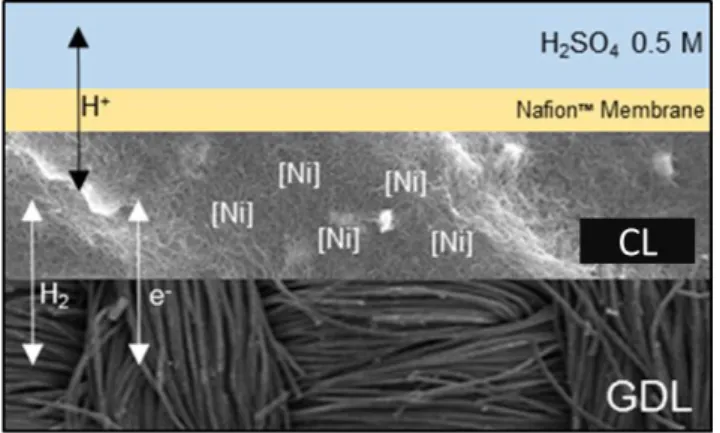
Figure 13. Schematic representation of a fuel cell anode. GDL is a gas diffusion layer and CL the catalytic layer.
Figure 13 present a schematic representation of a finished electrode, composed of a porous, conductive backing material, the GDL, onto which the catalytic layer (CL) containing the catalyst and carbon nanotubes is deposited. In some cases, a proton exchange Nafion membrane (yellow) is added between the CL and the electrolyte (blue). In order to enable integration in fuel cells, Nafion is added as an ionomer throughout the thickness of the CL in order to ensure a thorough proton relay in the entire thickness of the electrode in the absence of electrolyte.
7. State of the art of anodes for HOR
We here give the current densities of several anodes in context (experimental conditions and electrolyte), in so-called liquid electrolyte half-cell experiments. In this setup, the anode catalyst is deposited onto a GDL, secured within a sample holder that enables gas diffusion from the back as well as electrical conductivity and a known surface of the electrode is exposed to a liquid electrolyte such as an acid in water (See Figure 14). Current densities are then assessed in a classical three-electrode electrochemical setup. This allows comparison of the capacities of standalone anodes for HOR. One way of giving the benchmarking values for a supported HOR catalyst is either current density at a given overpotential, or overpotential required to reach a given current density.73 In our case, we note jox the current density for HOR at a given potential.
This is the common benchmarking metric used in our lab for bio-inspired catalytic materials. However, for Pt-based catalysts which display a fully micro-reversible mechanism for HOR and HER, the benchmarking value is the so-called exchange current density (either j0 in
A/cm²geo in which the surface in the geometric surface of the electrode, or i0,s in A/cm²Pt in
which the surface is the specific surface of Pt in the electrode). It represents a sort of "idle speed" of the catalyst, and describes its full catalytic capacity independently of environmental factors. We determine j0 values for our best electrodes in Chapter III.
35
Figure 14. Schematic representation of a half-cell setup. WE = Working Electrode, Ref = reference electrode, CE = Counter Electrode.
Table 2 hereafter gathers the jox values for several catalysts and j0 values for state of the art,
ultra-low loading platinum catalysts (ULL-Pt). It appears from this table that the best current densities of CyEster bio-inspired anode which sit at 10 % of the best performances of an ULL-Pt electrode. Literature on Pt-based anode catalysts in half-cell setup is quite rare, due to the fact that most of the research effort is focused on the ORR along with the very high exchange current densities of HOR on Pt, which are very difficult to measure accurately. The first two entries in this table showcase the improvement over seven years in design and benchmarking of Pt/C catalysts for HOR: with a six-fold decrease in Pt loading, similar jox are observed with
a threefold increase in j0. According to the authors, this increase in j0 is rather due to better
measurement conditions and fitting of the data than to an intrinsic difference between catalysts. The other non-noble metal-based catalyst for HOR presented here, a tungsten carbide, shows an activity about 20 % as good as that of the ULL-Pt electrode at 150 mV of overpotential.
Catalyst j0 (mA/cm²) jox (mA/cm²) ηjox (mV) T (°C) Electrolyte Yearref
Pt/C 10 µg/cm² 26 210 150 50 H2SO4 1 M 200874 400 350 Pt/C 1.7 µg/cm² 70 250 200 25 H2SO4 0.5 M 201575 CyEster - 13 350 25 H2SO4 0.5 M 201676 40 85 WC - 40 150 65 Nafion 212 200924,25
Table 2. Values of j0 and jox for different catalytic systems for the HOR. For jox, the overpotential (ηjox)
36
The state of the art of i0,s values for Pt/C catalysts is very well reported in two papers by the
group of Gasteiger,77,78 however they are of little use for comparison with our systems. Indeed
the value of i0,s relies on the specific surface area of the catalytic nanoparticles and is quite
meaningless when describing molecular catalysts. Instead, we compare in Chapter II our best performing catalysts to Pt/C as shown in Table 2 using jox and j0 as benchmarking metrics.
8. Ambitions of this work
In this work, we focus on bioinspired DuBois-type HOR catalysts, but rather than try and design further, more efficient catalysts, we aim instead to investigate the optimization of some of the most promising bio-inspired electrocatalytic materials as well as their implementation in fuel cells. Our current point of view, based on previous work in our group and others, is that there is little interest in finding the “perfect” molecular catalyst without an idea of how to make the best out of it. More generally, it is our idea that studying a catalyst destined for practical applications in a technologically irrelevant environment may be of great interest to elucidate mechanical aspects of the reaction but does not yield great insight as to the practicality of its use in real life. We hope to have shown in this introduction that the diversity of catalysts available and their intrinsic properties are such that it is now of interest to try and increase the technology-readiness level of some of these. In this thesis, we first consider the choice of a “champion” bio-inspired catalyst as well as the effects of catalytic ink formulation and ionomer implementation on catalytic activity, and look at the optimization of the environment of the catalyst on its activity. Then, we take a closer look at a particular type of electrode prepared during this project that shows qualitatively new results at high overpotentials and characterize the physical chemistry of its unique behaviour, rationalizing it with regard to previous results. Finally, we describe the implementation of those optimized electrodes in fully functional, noble metal-free PEMFCs.
38
Chapter I – Catalyst choice and effect of ionomer
In this first chapter, we present several techniques to characterize the molecular catalysts and their support materials described in the introduction, in particular the three DuBois catalysts on which this work focuses. We then take a close look at the use of Nafion, a PTFE-based ionomer which serves as a proton relay. Its use in fuel cell electrodes is as critical as it is problematic: Nafion can be detrimental to the activity of most catalytic sites but is required for good interfacing of the electrode with the proton-exchange membrane, and at the present time any molecular catalyst susceptible of integration has to be compatible with Nafion.
1. Characterization of the molecular catalysts
The three DuBois catalyst based electrodes presented in the introduction are shown together in Figure 1. In this part, electrodes containing these three catalysts are characterized, described and benchmarked.
Figure 1. Clockwise, from top left: MWNT/CyPy, MWNT-COOH/CyArg and MWNT-NH2/CyEster
deposited onto a GDL. R1 = CH2-pyrene, R2 = Arginine, R3 = Ph-CH2CH2COOH or
39 a. Catalytic activity
The preparation of these three types of electrodes is different because of the intrinsic differences in the grafting strategies. It is described in detail in the experimental section, but hereafter is a succinct description for each electrode.
MWNT-NH2/CyEster is prepared as previously described,69 by first filtering a suspension of
MWNT onto the GDL to form a mat onto which a diazonium salt is reduced to decorate the MWNT with amino functions, yielding MWNT-NH2. This electrode is then soaked in a solution
of CyEster in DMF in the presence of a weak base, 2,6-lutidine, to enable covalent amide bonding.
MWNT/CyPy is prepared by drop casting a suspension of the pristine MWNTs in EtOH onto the GDL, letting it dry and then drop casting a solution of CyPy in DCM onto the MWNT mat. This is in contrast with what was previously done in the group, where the MWNT were vacuum-filtered onto the GDL and the obtained electrode was soaked in a solution of the catalyst.79 This
new method is preferred as it allows easier quantification and control of the amount of CyPy deposited as well as economy of catalyst.
Finally, MWNT-COOH/CyArg is prepared as an all-in-one ink, by premixing the suspension of MWNT-COOH in ethanol with the solution of CyArg in pH 6 MES:HEPES buffered water. This ink is simply drop-casted onto the GDL and air-dried. Previous reports in our group used a similar method to that used for MWNT-CyPy in which the MWNT-COOH were deposited first,80 however we have found better reproducibility with our current method.
Figure 2. Comparison of the two half-cell setups, side (A) and front (B) views. Classical half-cell, S = 0.5 cm² on the left and so-called micro half-cell, S = 0.06 cm² on the right of each picture.
40
Catalytic activity is assessed through cyclic voltammetry experiments. A simple half-cell apparatus (see Figure 2) was made in house, with a small surface area (of the order of 0.06 cm², on the right in panels A and B, Figure 2).) which allows facile and efficient benchmarking while using very small amounts of catalyst. No notable changes in catalytic performance were observed compared to the previous experimental setup in our lab, a similar half-cell with a surface area of 0.5 cm² (on the left in panels A and B, Figure 2). In Figure 3, the catalytic behaviour of these catalytic materials is compared at pH 0.3 in aqueous 0.5M H2SO4 electrolyte,
in the presence of a 100% atmosphere of H2 gas fed through the back of the working electrode.
Figure 3. Comparison of the catalytic behaviours of the three systems, CyPy, CyEster and CyArg, grafted on their respective nanotubes: MWNT, MWNT-NH2, MWNT-COOH. Half-cell setup, S = 0.063
cm², electrolyte is H2SO4 0.5 M in H2O, pH 0.3, 298K and PH2 = 1 atm.
MWNT/CyPy and MWNT-NH2/CyEster display similar shapes with an overall reversible
HER/HOR catalytic ability, and a similar catalytic bias towards the HER. This is in line with previous results from our group.72,76,81 The current densities of MWNT-NH2/CyEster are larger
for both HER and HOR, despite similar site loadings. MWNT-COOH/CyArg, on the other hand, while it still displays reversible catalytic activity, shows a very strong bias for HOR, as described in solution at this pH52,82 or after grafting onto SWNT-COOH.80 However, catalytic HOR activity reaches a catalytic plateau above 100 mV of overpotential.
![Figure 5. Selected biomimetic complexes of the active sites of [FeFe]- and [NiFe]-hydrogenases](https://thumb-eu.123doks.com/thumbv2/123doknet/12881993.370086/27.892.144.764.106.428/figure-selected-biomimetic-complexes-active-sites-fefe-hydrogenases.webp)


![Figure 8. FT of EXAFS spectra of the measured spectrum of grafted CyEster (black) with the two fits resulting from linear combination of CyEster P2 [36,3%] (red) and CyEster P4 [52,4%] (blue) with the Ni-hexaaqua-complex](https://thumb-eu.123doks.com/thumbv2/123doknet/12881993.370086/48.892.171.726.103.434/measured-spectrum-cyester-resulting-combination-cyester-cyester-hexaaqua.webp)


