HAL Id: cea-02338571
https://hal-cea.archives-ouvertes.fr/cea-02338571
Submitted on 24 Feb 2020
HAL is a multi-disciplinary open access
archive for the deposit and dissemination of
sci-entific research documents, whether they are
pub-lished or not. The documents may come from
teaching and research institutions in France or
abroad, or from public or private research centers.
L’archive ouverte pluridisciplinaire HAL, est
destinée au dépôt et à la diffusion de documents
scientifiques de niveau recherche, publiés ou non,
émanant des établissements d’enseignement et de
recherche français ou étrangers, des laboratoires
publics ou privés.
J. Hure, B. Tanguy, C. Ritter, S. Bourganel, F. Sefta
To cite this version:
J. Hure, B. Tanguy, C. Ritter, S. Bourganel, F. Sefta. Extensive investigation of the mechanical
properties of a Chooz A internal component. Fontevraud 9, Sep 2018, Avignon, France. �cea-02338571�
3 EDF Lab Les Renardières, F-77818 Moret-sur-Loing, France
* Main Author, E-mail: [email protected]
Keywords:Austenitic stainless steel, Tensile properties, Toughness, Fracture mechanisms
Introduction
In PWR’s, internals made of austenitic stainless steels (Cold Worked (CW) 316 austenitic steels for bolts, 308 for welds and Solution Annealed (SA) 304 for baffle plates, former and core barrel) are sub-jected to irradiation embrittlement with doses that will reach up to 80 dpa locally after 40 years of oper-ation at temperatures between 280°C and 380°C. The irradioper-ation exposure alters the nanostructure and so consequently do the mechanical properties of stainless steels: it increases the yield strength, de-creases ductility and promotes plastic instabilities. These evolutions of mechanical properties with irra-diation may have dramatic consequences on the fracture properties: CW316 and SA304 have been shown to become sensitive to Stress Corrosion Cracking in PWR environment, a phenomenon known as IASCC [1] affecting baffle-to-former bolts. Moreover, neutron irradiation at low temperature generally causes a strong decrease of fracture toughness. Austenitic stainless steels are characterized by their ductility and stable crack propagation. However, fracture toughness (as measured by the J-integral at the onset of crack propagation JIc [2]) may decrease by a factor up to ten after few dpa of irradiation,
with a reduced stable crack propagation, or even brittle-like unstable crack propagation for the highest irradiation levels. Detailed reviews of the available experimental data have been provided regarding the evolution of tensile properties and fracture toughness of austenitic stainless steels with irradiation [1,2,3] at temperatures about 330°C, discussing the effects of materials, irradiation conditions (temperature, neutron spectrum) and providing correlations or bounding curves for the evolution of these properties with irradiation. Most of the data, especially for high doses, comes from irradiation in fast-spectrum reactors, while the remaining have been obtained from materials retrieved from commercial LWR’s or irradiated in mixed spectrum Materials Testing Reactors (MTR). For tensile properties, both subsets of data have been shown to follow the same trends with respect to the saturation of yield stress and me-chanical strength with irradiation [2]. However, few data available from LWR’s are above the data from fast reactors. Similarly, for fracture toughness tests, only limited data are available from LWR irradiated materials, limited to doses less than about 10dpa for 304, and seems to fall below the bounding curves established from fast-reactors irradiation. More experimental data - tensile properties and fracture tough-ness - from austenitic stainless steels irradiated in LWR conditions are thus required to provide reliable predictions of the evolution of tensile properties and fracture toughness with irradiation in LWR condi-tions. In addition, fracture mechanisms of irradiated austenitic stainless steels depend on irradiation conditions (dose and temperature) and test conditions, as reviewed recently in [4]. Void growth to coa-lescence is observed at the unirradiated state and appears to remain dominant at 330°C for irradiated materials in LWR conditions, but intergranular fracture is also reported at lower test temperature or in aqueous environment (IASCC). At higher irradiation temperature, different fracture mechanisms have been described, such as channel fracture or nano-void growth to coalescence, which imply to treat with great caution the fracture toughness data obtained from high temperature irradiation to LWR conditions. Finally, a deep understanding of the fracture mechanisms will be required to go beyond correlation laws and to provide physically based fracture models for irradiated stainless steels.
The aim of this study is thus to provide tensile properties, fracture toughness estimation and observa-tions of fracture mechanisms of a 304 austenitic stainless steel irradiated at high doses (>10dpa) in PWR conditions. First, the material and irradiation conditions are described as well as the machining of the tensile and fracture toughness samples. Tensile properties and fracture toughness properties are then reported, with Scanning Electron Microscope (SEM) observations of the fracture mechanisms. Re-sults are finally discussed with respect to available literature data.
Material and Samples preparation
This study is based on a component from the lower internals (Fig. 1a) of the French decommissioned PWR Chooz A operated for 24 years (between 1967 and 1991) [5]. Chooz A was the first PWR reactor built in France, with an electric power of 305MW. Unlike newer PWR designs, baffles made of 304 austenitic stainless steel (Fig. 1a) separated fuel assemblies at the periphery of the core. The chemical composition of the material is given in Tab. 1. The irradiation temperature of the component used in this study ranges from 290°C to 330°C, and doses up to 38dpa were estimated based on neutronic compu-tations. One of these baffles was cut into pieces as sketched on Fig. 1b.
(a) (b)
Figure 1: (a) Chooz A Reactor Pressure Vessel [6], (b) Location of the component used in this study
C S P B Mo Co Si Mn Cr Ni V Nb Cu Ti
0.06 0.003 0.011 <0.0005 0.02 0.034 0.78 0.96 18.6 9.3 0.099 <0.02 0.089 <0.003
Table 1: Chemical composition (%wt) of 304 austenitic stainless steel
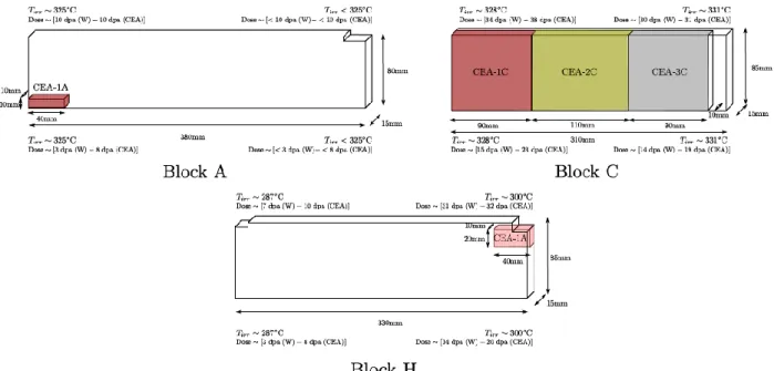
Blocks A, C and H were cut into sub-blocks used to machine tensile and fracture toughness samples. Fig. 2 indicates the location of the sub-blocks (referred to as CEA-1A,-1H,-1C,-2C,-3C), as well as eval-uations of irradiation temperature and dose. For the latter, two methodologies were used to compute the dpa levels that differs especially for the block A. Additional evaluation of the dose is currently in progress, based on activity (60Co) measurements at precise locations along the blocks and neutronic
computations, and results will be reported elsewhere. In the following, dose reported for the samples corresponds to the evaluation denoted (W) on Fig. 2, assuming linear dose gradient along the block due to their relatively small sizes. Ten flat tensile specimens were machined with gage lengths aligned with the top-bottom axis of the baffle through wire-cut electrical discharge machining and conventional mill-ing. Two geometries are considered: the first one is shown on Fig. 3a and referred to as M1, the second one is homothetic to M1of ratio 2, and is referred to as M2. Seven fracture toughness 1/2T Compact Tension (CT) specimens were also machined through wire-cut electrical discharge machining and con-ventional milling for the pin holes and side grooves (Fig. 3b). All samples machining, mechanical testing and SEM observations reported hereafter were performed at the LECI hot cells facility (CEA Saclay).
Top
Figure 2: Location of the sub-blocks (CEA-1A,-1H,-1C,-2C,-3C) used to machine the tensile and fracture toughness samples. Irradiation temperature and dose evaluations. Right (resp. left) part of each block
corresponds to top (resp. bottom) part of the baffle. No estimation of dose gradient along the (15mm) thickness is available.
(a) (b)
Figure 3: Samples geometry: (a) Tensile specimen (M1), (b) 1/2T Compact-Tension specimen (Dimensions in mm)
Tensile properties
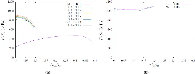
In order to evaluate the conventional tensile properties as a function of irradiation dose and temperature, tensile tests were performed on specimens shown in Fig. 3a at both room temperature and 330°C. Universal testing machines in hot cells were used under displacement control at a mean strain rate of 5x10⁻⁴s-1. Conventional tensile curves are shown on Fig. 4 and conventional tensile properties (yield
stress at 0.2% plastic strain YS, ultimate tensile strength UTS, elongation at the onset of necking /
max-imal load Am and elongation at fracture Ar) are summarized in Tab. 2. Tests performed at 330°C on
specimens irradiated at about 330°C indicate an overall saturation of mechanical properties for doses higher than about 14dpa, although two specimens (3C-TR7 and 3C-TRH1) have a slightly higher yield
stress. The comparison between specimens 1C-TR2, 3C-TR7 and 1H-TR9 shows unexpectedly an ef-fect on the irradiation temperature, with lower yield stress / mechanical strength at lower temperature. The tensile properties of specimens 3C-TR7 and 3C-TRH1, which differs from the geometry of the sam-ples, are very similar, indicating an absence of effect of the sample geometry (in the range considered) on tensile properties of highly irradiated austenitic stainless steels. Specimen 1A-TR9 was found to have tensile properties similar to unirradiated 304 steel, although the irradiation dose was estimated to be higher than 3dpa. Such result is consistent with TEM observations (not shown) showing only few irradi-ation defects and raises questions about the dose estimirradi-ation, especially for the upper and lower part of the baffle where flux gradients are expected. Snapshot of the tensile test at 330°C (Fig. 5a) shows a strong necking associated with very large local strains, with a final failure through the appearance of a shear band (Fig. 5b). Tests performed at room temperature are shown on Fig 4b for two specimens with similar irradiation dose and temperature. A very good reproducibility of the tests is observed, show-ing early neckshow-ing (defined as a drop of the load), followed by a stress plateau and final hardenshow-ing be-havior up to fracture. Yield stress and mechanical strength are significantly higher than the ones meas-ured at 330°C. Snapshot of the tensile test (Fig. 6a) indicates that the stress plateau corresponds to the propagation of a stable neck along the gage length of the sample. Hardening behavior starts at the end of the propagation of the stable neck, and final fracture surface is perpendicular to the tensile axis (Fig. 6b).
(a) (b)
Figure 4: Conventional tensile curves: Conventional stress as a function of conventional plastic strain (a) at 330°C and (b) at room temperature
Table 2: Conventional tensile properties as a function of irradiation dose, irradiation temperature Tirr, and
test temperature Ttest: yield stress at 0.2% plastic strain YS, ultimate tensile strength UTS, plastic
(a) (b)
Figure 5: Tensile specimen 3C-TR7 (~30dpa) tested at 330°C: (a) Necking observed during the tensile test, (b) Side view of the fracture surface
(a) (b)
Figure 6: Tensile specimen 2C-TR6 (~25dpa) test at RT: (a) Stable neck propagation observed during the tensile test, (b) Side view of the fracture surface
Fracture properties
1/2T Compact Tension specimens were precracked in fatigue at room temperature (f=5Hz, ΔKini =
18MPa√m, Kmax/Kmin=0.25, Cg=ln(ΔKfin/ΔKini)/(af-a0)=-0.38). Crack length monitoring was performed
through compliance technique with an extensometer measuring the Crack Mouth Opening (CMOD) along the load-line of the sample. Depending on the specimen, more than 30k up to 120k cycles were necessary for the crack to reach a targeted a0/W ratio of 0.6 (a0 ≈ 15mm). Fracture toughness tests
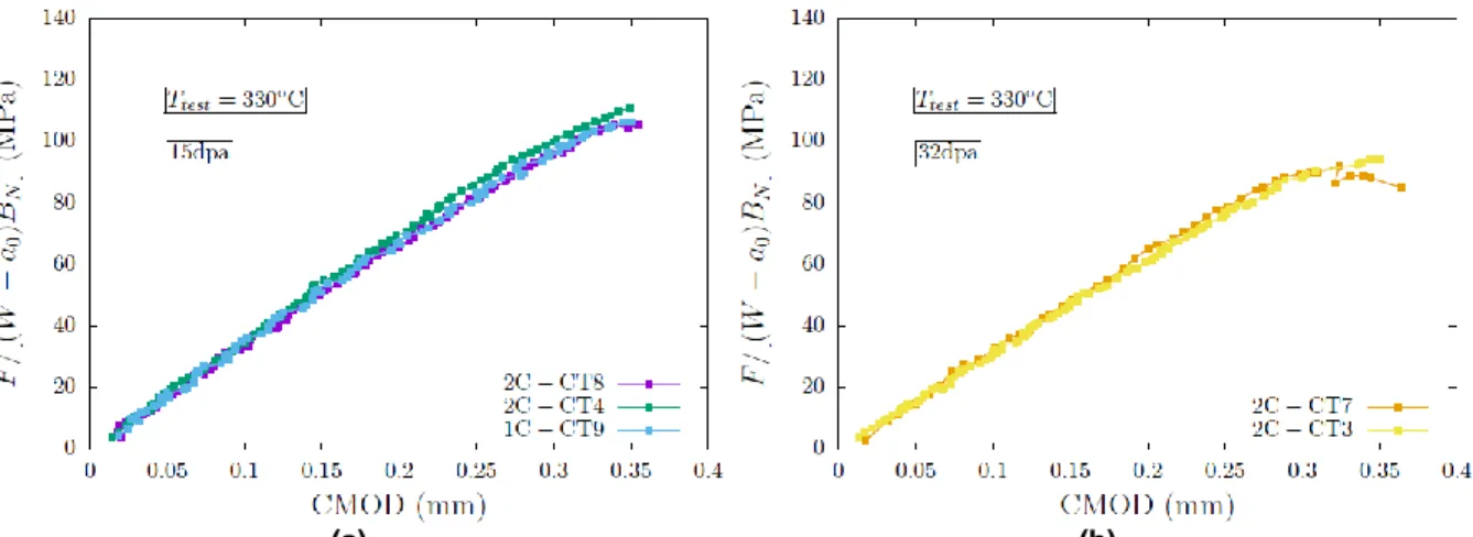
were performed in a furnace at 330°C under Argon flow. Except for specimen 2C-CT7, a crosshead displacement speed of 0.8mm/min was applied (corresponding roughly to 0.16mm/min of CMOD speed at the end of the test), with hold time of 30s every 20μm displacement followed by partial discharge (15% of the hold time load) of the specimen and reloading. Due to very limited stable crack growth, compliance technique was not used to estimate the crack length during the test. Instead, tests were stopped shortly after the peak load, and samples were cooled down to room temperature and finally cracked in fatigue. Load vs. Crack Mouth Opening Displacement are given in Fig. 7, showing a good reproducibility of the tests. Two of the seven CT specimens (not reported in Fig. 7) were found to have initial fatigue crack slanted, preventing using them to evaluate fracture toughness with standardized methods. The five other CT specimens have relatively straight crack front: initial fatigue crack length and stable crack growth were measured through nine-point measurements (see Fig. 8), and the corre-sponding J values were computed according to ASTM1820 [7]. For each test, the initial crack length, stable crack growth and associated J (and K according to K=√[EJ/(1-ν2)], with E=200GPa and ν=0.3)
values are given in Tab. 3.
Table 3: Results of the fracture toughness tests at 330°C: Geometry of the 1/2T CT specimens (Thickness B and net thickness between the side grooves BN, width W, fatigue crack length a0, final crack length af
and propagation Δa= af - a0), J-integral value (and stress intensity factor) for the given crack propagation
Specimen Dose (dpa) B (mm) BN (mm) W (mm) a0 (mm) af (mm) Δa (mm) J (kJ/m2) K (MPa√m) 2C-CT8 ~15 12.25 9.66 24.79 14.07 15.28 1.21 38 91 2C-CT4 ~15 12.56 9.64 24.76 13.74 14.23 0.49 37 90 1C-CT9 ~15 12.21 9.56 24.71 14.48 14.70 0.22 37 90 2C-CT7 ~32 12.34 9.62 24.75 14.65 14.65 - 38 91 2C-CT3 ~32 12.49 9.95 25.90 14.80 15.28 0.48 24 73
(a) (b)
Figure 7: Load (normalized by the remaining ligament section) as a function of Crack Mouth Opening Dis-placement (CMOD) for fracture toughness tests at 330°C for (a) 15dpa and (b) 32dpa samples.
(a) (b) (c)
(d) (f)
Figure 8 : Facture surfaces of samples (with nine points crack measurements) (a) 2C-CT8, (b) 2C-CT4, (c) 1C-CT9, (d) 2C-CT7 and (e) 2C-CT3. Three different regions can be observed on each fracture surface characterized by their different colors (and delimited with yellow and red dots): initial fatigue crack, crack
propagation during the toughness test, and final fatigue cracking, from left to right
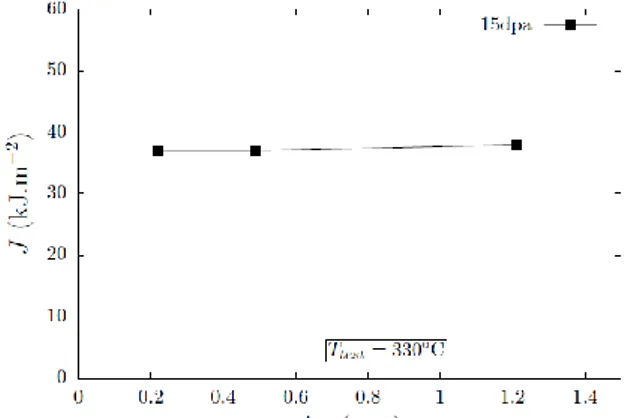
For the specimens irradiated up to 15dpa, normalized load vs. CMOD curves are very reproducible (Fig. 7a), and three different values of crack growth were obtained (Fig. 8a,b,c), allowing plotting an estimate of the J-da curve, under the assumption that the three specimens have the same fracture resistance (Fig. 9). Tearing modulus appears to be close to zero, so that J (of K) values reported can be considered as close to initiation values. For the specimens irradiated at 32dpa, only one of them (2C-CT3) was interrupted during the stable crack growth phase, while unstable crack growth occurred for the other (2C-CT7). Estimation of initiation J-integral for the latter was performed assuming crack started to prop-agate at the peak load. Fracture toughness evaluations at 15dpa are found to be very reproducible for the material used, leading to values close to 90MPa√m. A slight decrease of fracture toughness with irradiation between 15dpa and 32dpa is observed, down to minimal value of 73MPa√m.
Figure 9 : J-da curve obtained from interrupted tests at 330°C on three 1/2T CT specimens irradiated to 15dpa.
SEM observations
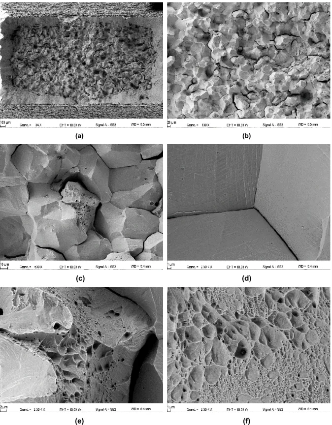
Fracture surfaces of tensile specimens 2C-TR5 (tested at 330°C) and 2C-TR6 (tested at 20°C) were observed with Scanning Electron Microscope (SEM), under secondary electron mode. At 330°C (Fig. 10), the fracture surface is characterized by the presence of dimples of various sizes and shapes, indi-cating a void growth to coalescence fracture mechanism. Depending on the location of the fracture surfaces, equiaxed or elongated dimples are observed, correlated a priori with the local orientation of the fracture surface with the tensile axis. When the local fracture surface is parallel to the loading axis, dimples are mostly equiaxed while they are elongated in regions where the fracture surface is tilted with respect to the loading axis. At lower magnification, the presence of elongated dimples corresponds to regions appearing mostly flat. Two populations of dimple sizes can be observed, the large one being of about 5 microns diameter often associated with spherical precipitates inside, while the second popula-tion has dimples less than 1 micron diameter often free of precipitates. Fracture surface of the specimen tested at room temperature (Fig. 11) shows a large region located at the middle of the specimen which is perpendicular to the tensile axis and almost completely intergranular in nature, while an external layer, slanted, is transgranular. Images at different magnifications of the intergranular region are shown in Fig. 11b,c,d. Numerous intergranular cracks can be observed, indicating that the fracture mechanism at room temperature on tensile specimen may not correspond to the propagation of a single (intergranular) crack, but should be considered rather to a coalescence process of multiple intergranular cracks. Inside the intergranular region, few regions with dimples are observed that are surrounded by intergranular facets, as well as cracked or debounded precipitates. The intergranular or transgranular nature of the ductile region is however difficult to assess. The external layer of the fracture surface is fully ductile, characterized by the presence of dimples similar to what has been already described for the specimen tested at 330°C, with two different dimple sizes population. SEM observations of CT specimens fracture surfaces are in progress, and will be reported elsewhere.
Discussion
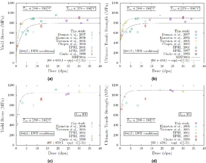
The evolution of tensile properties (yield stress and ultimate tensile strength) are plotted as a function of dose in Fig. 12, considering the available data in the literature and results obtained in this study, and restricting to 304(L) materials irradiated in LWR conditions. The MRP correlation curves [3] for solution-annealed austenitic stainless steels (304(L), 347) irradiated and tested at temperature close to 330°C, and referred to as MRP2004, are also compared to the data. As discussed in [1], most of the data used to get the MRP2004 curves comes from materials irradiated in fast reactors, which, albeit following the same trends than materials irradiated in LWR conditions, might not be quantitatively representative of the latter. This is confirmed by the additional data provided in this study that are significantly harder (about 50MPa) than the predictions of MRP curves, for both yield stress and ultimate tensile strength. New (almost upper-bound) fitting curves are proposed to describe the hardening of 304(L) materials under LWR conditions irradiated and tested at a temperature close to 330°C. Less data are available for 304(L) materials irradiated in LWR conditions at a temperature close to 330°C but tested at room
temperature. Results are given in Fig. 12(c,d) with proposition of (almost upper-bound) fitting curves.
(a) (b)
(c) (d)
(e) (f)
Figure 10: SEM fracture surface observations of tensile specimen 2C-TR5 (~24dpa) tested at 330°C
(b)
(f)
(c, d)
(a) (b)
(c) (d)
(e) (f)
(a) (b)
(c) (d)
Figure 12: Evolution of yield stress and ultimate tensile strength for 304(L) materials under LWR irradia-tion condiirradia-tions, and tested at a temperature close to 330°C (a,b) or at room temperature (c,d).
Fracture surfaces of tensile specimens shown on Fig. 10 and 11, tested at 330°C and RT respectively, are fully consistent with observations obtained for the same material in [10], as well as with critical assessment of fracture observations provided in [4]. In particular, the fully dimpled surface of the spec-imen tested at 330°C – without any occurrence of channel fracture - indicate that, for 304(L) materials irradiated in LWR conditions up to high doses, classical models of ductile fracture based on void growth to coalescence could be used to predict failure, at least for the mechanical loading conditions obtained in tensile tests. SEM observations of CT specimens tested at 330°C are in progress, and would allow extending this statement to mechanical loading conditions relevant to crack-tip. Specimen tested at room temperature exhibits both stable necking propagation and (almost-) fully intergranular fracture. It has been proposed in [4,17] that both observations could be rationalized by the fact that a martensitic transformation occured, which remains to be assessed in our study through TEM observations.
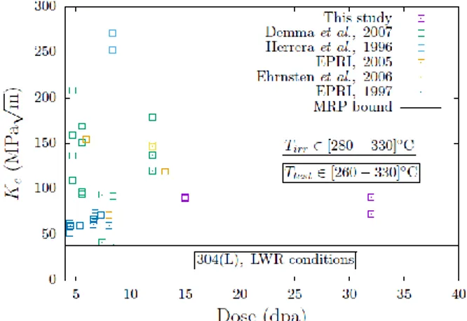
Comparisons of fracture toughness estimations of 304(L) materials irradiated in LWR conditions to high doses (> 4dpa) are shown on Fig. 13. Considerable scatter are observed, resulting from metallurgic reasons (as in [8] associated with the presence of stringers) or that may result from significant differ-ences in tensile properties (as for the data in [9] that have rather low yield stress and ultimate tensile strength compared to other materials irradiated to similar doses). Fracture toughness evaluation ob-tained in this study are within the scatter of previous available data. A slight decrease of fracture tough-ness is observed between 15dpa and 32dpa that would require further experimental data at higher doses for materials irradiated in LWR conditions to assess to absence of additional embrittlement.
Figure 13: Evolution of fracture toughness with irradiation for 304(L) material irradiated in LWR condi-tions.
Conclusion
An extensive investigation of the mechanical properties of 304 internal component from the decommis-sioned Chooz A PWR was performed, including the evaluation of tensile properties as a function of irradiation dose and test temperature, and fracture toughness at 330°C. Saturation of the tensile prop-erties with irradiated is observed above 15dpa. Yield stress and ultimate tensile strength are found to be higher than the ones obtained from fast reactors irradiation, confirming and extending trends detailed in [1] and providing additional data on austenitic stainless steels irradiated in LWR conditions at high doses that are still scarce in the literature. Correlation curves were adjusted on 304(L) data irradiated in LWR conditions. SEM observations have shown that failure occurs on tensile samples through void growth to coalescence at 330°C and through intergranular cracking at room temperature. Fracture toughness was evaluated for the first time on 304 material irradiated in LWR conditions at very high doses (15 and 32dpa), through interrupted tests on 1/2T compact tension specimens. For the two doses, fracture toughness was estimated in the range [70-90]MPa√m, within the (large) scatter of the data from the literature on 304(L) material irradiated in LWR conditions above 4dpa, but significantly higher than the lower-bound of 38MPa√m proposed in [3]. The tearing modulus is however very low so that limited stable growth is expected with such highly irradiated material.
Acknowledgment
The authors would like to acknowledge D. Schildknecht, Y. Sibille and L. Rancoeur for preparing the samples, T. Perez, J. Pegaitaz and P. Grange for performing the tensile tests, E. Guillot for performing the toughness tests, and M. Azera and A. Courcelle for the SEM observations. Support from LECI hot cells staff is also greatly acknowledged.
References
1) O. K. Chopra and A.S. Rao, “A review of irradiation effects on LWR core internal materials – IASCC susceptibility and crack growth rates of austenitic stainless steels”, J. Nuc. Mat. 409, 235-256 (2011)
2) O. K. Chopra and A.S. Rao, “A review of irradiation effects on LWR core internal materials – Neutron embrittle-ment”, J. Nuc. Mat. 412, 195-208 (2011)
3) Materials Reliability Program. A Review of Radiation Embrittlement for Stainless Steels (MRP-79) Revision 1. EPRI Technical Reports, 1008204, (2004)
4) A. Hojna, “Overview of Intergranular Fracture of Neutron Irradiated Austenitic Stainless Steels”, Metals, 392, doi:10.3390/met7100392, (2017)
5) O. Goltrant et al., “Eléments internes inférieurs: apports de l’expertise d’une cornière de Chooz A”, Fontevraud IV Conference, (1998)
6) J. Boucau et al., “Chooz A, First Pressurized Water Reactor to be dismantled in France”, WM2013 Conference, Phoenix, Arizona, USA, (2013)
8) A. Demma et al., “Fracture toughness of highly irradiated stainless steels in boiling water reactors”, 13th Inter-national Conference on Environmental Degradation of Materials in Nuclear Systems – Water Reactors, 2007, Whistler, B.C., Canada.
9) U. Ehrnsten et al., “Fracture toughness of stainless steels irradiated up to ~9dpa in commercial BWRs”, 6th International Symposium on Contribution of Materials Investigations to improve the Safety and Performances of LWRs, 2006, Fontevraud, France.
10) A. Toivonen et al., “Fractographic observations on a highly irradiated AISI 304 steel after constant load tests in simulated PWR water and argon after supplementary tensile and impact tests”, 12th International Conference on Environmental Degradation of Materials in Nuclear Systems – Water Reactors, 2005, Salt Lake City, USA. 11) O.K. Chopra et al., “Fracture Toughness and Crack Growth Rates of Irradiated Austenitic Stainless Steels,”
Argonne National Laboratory for U.S. Nuclear Regulatory Commission, NUREG/CR-6826, 2003.
12) Materials Reliability Program, Hot Cell Testing of Baffle/Former Bolts Removed from Two Lead PWR Plants (MRP-51), EPRI Technical Reports, 1003069, 2001
13) VTT (Technical Research Center of Finland) BWR Vessel and Internals Project: Fracture Toughness and Ten-sile Properties of Irradiated Austenitic Stainless Steel Components Removed From Service (BWRVIP-35), Elec-tric Power Research Institute (EPRI), Palo Alto, CA: June 1997. EPRI TR-108279.
14) W.L. Clarke et al., “Evaluation of the Fracture Toughness of Irradiated Stainless Steel Using Short Rod Speci-mens,” Effects of Radiation on Materials:14th International Symposium, Philadelphia, 1990, USA.
15) M. L. Herrera et al., “Evaluation of The Effects of Radiation on the Fracture Toughness of BWR Components,” International Conference on Nuclear Engineering (ICONE-4), Volume 5, pp. 245-251, ASME 1996.
16) Materials Reliability Program. Fracture Toughness Testing of Decommissioned PWR Core Internals Materials Samples (MRP-160). EPRI Technical Reports, 1012079, 2005
17) B. Margolin et al., “The radiation swelling effect on fracture properties ad fracture mechanisms of irradiated austenitic steels. Part I: Ductile and fracture toughness, J. Nuc. Mat. 480, 52-68 (2016)
![Figure 1: (a) Chooz A Reactor Pressure Vessel [6], (b) Location of the component used in this study](https://thumb-eu.123doks.com/thumbv2/123doknet/12964215.377078/3.892.122.789.325.633/figure-chooz-reactor-pressure-vessel-location-component-study.webp)