O
pen
A
rchive
T
OULOUSE
A
rchive
O
uverte (
OATAO
)
OATAO is an open access repository that collects the work of Toulouse researchers and
makes it freely available over the web where possible.
This is an author-deposited version published in :
http://oatao.univ-toulouse.fr/
Eprints ID : 12082
To link to this article :
URL :
To cite this version :
Lizy-Destrez, Stéphanie and Audas, Chloé
Scenarios optimization for a servicing inhabited space station at
Earth-Moon Lagrangian point (EML2). ( In Press: 2014) In: The
65th International Astronautical Congress, IAC2014, 29 September
2014 - 3 October 2014 (Toronto, Canada)
Any correspondance concerning this service should be sent to the repository
administrator:
[email protected]
IAC-14-D2.8-A5.4.4
SCENARIOS OPTIMIZATION FOR A SERVICING INHABITED SPACE STATION AT EARTH-MOON
LAGRANGIAN POINT (EML2)
Stéphanie Lizy-Destrez,
ISAE/SUPAERO, France, [email protected]
Chloé Audas,
ISAE/SUPAERO, France, [email protected]
Human Space exploration is nowadays at a turning point of its history. Space agencies collaborate in order to determine next steps in this context, through for example, the International Space Exploration Coordination Group (ISECG). Agreement has been reached to identify that human beings will be sent in the upcoming decades to Mars, Moon or asteroids surface. Among all the selected scenarios, locating a deep-space habitat in the vicinity of the Earth Moon Lagrangian (EML) points has been designated as being a cornerstone of the human space exploration strategy. This paper examines how to design a low cost mission, using the natural dynamics for station integration, crew rotations, cargo delivery and disposal. Moreover, it focuses on the impacts of the station architecture on the global optimization (in term of duration and delta-v) of the trajectories from LEO (Low Earth Orbit) departure to rendezvous in EML and return. Several scenarios have been studied to compare transfer strategies (direct, indirect, lunar flyby, weak stability boundaries) and modeling types (four-body problem, restricted circular three-body problem, ephemeris). Actually, optimization criteria strongly depend on the mission phase. When crew transit is considered, mission duration has mainly to be minimized, while cargo transportation will minimize the global delta-v. The main contribution of this paper lies in the rendezvous dimensioning encompassing both the architectural point of view and the dynamics point of view. This is the first time a study optimizes mission duration and delta-v over all phases of the journey for Human exploration.
I. INTRODUCTION
Human Space exploration is at its early stages. Beginning with Apollo missions and going on now with ISS utilizing, carrying space discoverers to Moon surface and perhaps, in next future on an asteroid or on Mars surface. According to International Space Exploration Coordination Group (ISECG) roadmap [1], next step should be the Moon vicinity and particularly, the Earth-Moon Lagrangian points’ location. An inhabited space station deployed in lunar space, around EML1 (Earth-Moon Lagrangian point 1) or EML2 could serve as gateway as a starting point to launch human missions to Mars and asteroids and support missions on Moon surface.
The project presented in this paper conducts analyses to design this inhabited space station, called THOR (Trans-lunar Human explORation) located at Earth-Moon Lagrangian point and evaluates the interactions between mission analysis and station architecture.
The section I deals with the mission context. It discusses the options thanks to Stakeholder needs analysis. Section II describes the Station architecture. Section III introduces the mission life-profile and potential scenarios. Section IV compares the performances of the scenarios and will suggest some recommendations.
I. MISSION CONTEXT
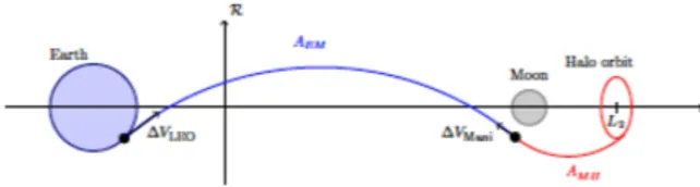
There are many space routes to reach Mars as a final goal for Human space exploration. Some of them go through Earth-Moon Lagrangian points, as hub to connect interesting locations in the solar system thanks low-cost trajectories (according to Weak Stability Boundaries transfer strategy) [2]. The main advantages to building a space station in EML1/EML2 are:
- To provide a gateway to all possible destinations (lunar
surface, NEOs, Mars and beyond)
- To serve as a spaceport for crew rotation from and to
Earth for cargo supply (fuel, food, water), exploration vehicles maintenance, preparations and operations for manned and unmanned missions
- To ensure continuous communication with Earth in
support to Lunar surface
- To offer a supporting structure for large telescopes
- To supply facilities for research in space
- To provide a test-bed to study the psychological aspect
for long-duration stay outside the Earth cradle
- To establish a space medical centre
The space medical centre will provide health and care to the permanent crew but also to the visiting astronauts. It will plan for majors illnesses or injuries, permit to stabilize patients when emergency re-entry is mandatory, provide quarantine
capabilities to avoid THOR contamination, ensure
countermeasures to minimize microgravity and shield the crew. Figure 1 depicts an artistic view of the Thor space station.
Figure 1: Station artistic view [4]
Since Farquhar’s first publication [5], space agencies and the scientific community have a growing interest for trajectories towards, around and from Lagrangian points (also called Libration points),.
Some space science missions take advantage of their particular properties. Among them, the SOHO satellite orbits around the Solar Lagrangian point L1 for Sun observation. PLANCK, a space observatory, launched in 2009 travelled on a small Lissajous orbit at L2 Lagrange point of the Earth-Sun system. The James Webb Space Telescope launch is scheduled for 2018 to replace the Hubble telescope. But the most famous is the ISEE-3 (International Sun-Earth Explorer) spacecraft that accomplished its mission on a halo orbit around the Sun-Earth L1 point in 1978 and then utilized the Sun-Earth-Moon system dynamics for other secondary goals [6].
A large literature exists on trajectory optimization in the three-body problem. Robert Farquhar published in the early seventies a paper to promote the idea to deploy an inhabited space station in a Halo orbit around EML2 [7]. Kathleen Howell summarized a wide range of knowledge concerning the mathematical representation of LP orbits [8] and methods to determine transfers from, to and among them [9].
The three-body problem refers to the motion of a particle (spacecraft, vehicle, celestial body) of a negligible mass, travelling in the gravitational field of two massive bodies (called the primaries). Joseph Lagrange demonstrated in 1772 [10] that five equilibrium points exits in this context. In the Earth-Moon system, they are named EML1 to EML5. Three of them (EML1 to EML3) are collinear and located on the Earth – Moon axis. The two equilateral last points are positioned at 60° leading and 60° trailing on the Moon orbit (as smaller primary body). Figure 2 presents the Libration points location without respect of the celestial bodies size and the distances scale.
Figure 2: Lagrangian points in the Earth-Moon system [11] Relative EML distance in the Earth-Moon reference frame are given in the Table 1:
EML Distance in km
EML1 to the Moon 62 690
EML2 to the Moon 59 746
EML3 to the Earth 386 345
EML4 and EML5 to the Earth 384 400
Table 1: EML distance in the Earth-Moon system [3]
The exact positions of the Libration points are computed by solving the Circular Restricted Three Body Problem (CR3BP), where the motion of the particle is restricted to the orbital of the two primaries, on circular orbits [2]. The RC3BP is an ideal model with some limitations, as compared to existing numerical models taking into account influence of other gravitational bodies like the Sun, anomalies in gravitational fields, but it is sufficient for the current study purposes.
As the three collinear points, from EML1 to EML3, are considered as semi-stable, it leads to stable orbits around them (low fuel budget for station-keeping) and guarantee low consumption of fuel for transfer trajectory from the Earth to EML and return.
There are four main types of trajectories for a particle orbiting around a Libration point: the Lyapunov orbits, the Lissajous orbits, the Halo orbits and Quasi-Halo orbits, defined as follows:
• Lyapunov orbits are planar periodic orbits in the orbital
plane of the primaries (xy-plane). Exact Lyapunov orbits only exist in the CR3BP.
• Lissajous orbits are three-dimensional quasi-periodic
orbits with an in- and out-of-plane oscillation.
• Halo orbits are three-dimensional periodic orbits.
Farquhar named them like from the shape when seen from Earth [12]. Exact halo orbits can only be computed in the CR3BP.
• Quasi-halo orbits are quasi-periodic orbits around a
halo orbit. They are intermediate between Lissajous and halo orbits.
The motion of the particle is described in a rotating reference frame centered at the center of mass of the Earth-Moon system (see Figure 3).
Figure 3: Circular three-body reference frame
Some examples of trajectories are provided on Figure 4. Ax is
y-axis and Az along the z-axis.
Figure 4: (a) Lissajous trajectory with Ay = Az = 3500 km
(b) Halo trajectory Az = 5000 km (c) Eight shape Lissajous
trajectory with Ay = Az = 3500 km (d) Lyapunov trajectory with
Ay = 3500 km [11]
Given all these theoretical elements confronted to stakeholder needs elicitation results, study presented in [3] compared advantages and drawbacks between EML1 and EML2 and between Halo, Lissajous and Lyapunov orbits The criteria selected for this trade-off analysis were: crew access from Earth, deployment and resupply, access to lunar location, communications, station keeping, exploration capabilities, Long term strategy and risk. The study concludes that a Halo orbit around EML2 should be the best place to locate the Thor space station.
Figure 5: Baseline scenario for Thor space station Figure 5 presents the selected baseline for Thor space station mission. Located at EML2, it would allow efficient access not only to the lunar surface, but also to many interesting destinations in the solar system thanks to the connection with the interplanetary super highway. Human missions could only visit few of those destinations, but Thor outpost could be helpful for building and servicing missions.
II. ARCHITECTURE
Taking into account lessons learned from previous human spaceflights, it is assumed that at most, thirty persons can be on board the THOR space station, for, at least, fifteen years life duration.
It was quantify [3] that on the one hand it must provide thirty days quarantine capability for, at least, six astronauts. On the other hand, the system shall ensure the crew return to Earth in between less than seven days, in case of life critical scenarios. As far as flexibility is concerned, the station is assumed to be composed of seven cylindrical modules. Each module has a maximal mass of twenty tonnes and external dimensions limited to a length of ten meters and five meters for the diameter. Those modules may look like the European Automated Transfer Vehicle (ATV).
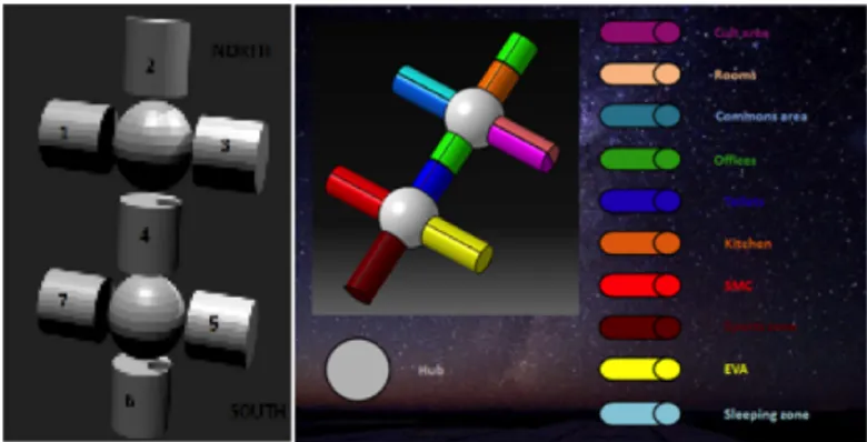
Figure 6: Thor space station functional architecture [13] A survey was performed to understand the impact of stressors on long-term duration human space exploration missions en route to Mars [15]. It particularly investigates the impact of stressors on habitability, i.e. the qualities to enable people to live and work in a safe and productive manner, of latent (permanent) and overt (linked to specific occurrences) stressors yielded. Co-living and co-working in the following extreme environment were identified as analogue scenarios for long duration space missions: Antarctic settings (Kerguelen and Concordia stations), caves extended exploration, remote sea-based oil drilling platforms, remote military outposts, drone pilots (from Jules Verne ATV control center) and Mars 520. Stressors were split into three main categories:
• Emotional and interpersonal issues (like monotony,
routine, confinement, emotional isolation, cultural differences, gender differences, lack of privacy...)
• Latent stressors linked to the extreme conditions issues
(communication time lag, low tolerance for errors, constant peril, sleep loss, impossibility of resupply, lack of comfort)
• Overt Stressors (like illness or death of crew member,
extra-vehicular activities (EVA), equipment
malfunction)
The survey was performed by interviewing, through an on-line questionnaire, participants of extreme identified scenarios. Every single participant has been asked whether he/she
experienced the above listed stressors and to attribute a severity.
The survey results analysis lead to architectural
recommendations and particularly on the functional and internal architecture of the Thor space station.
In order to avoid traffic congestion, spherical modules have been placed at the intersection of the three modules of the northern part and the three of the southern parts. These spherical modules can be compared to a crossroad and would function much the same as hubs. Windows would be added to their top parts to allow celestial viewing.
This functional repartition was established in order to reproduce the terrestrial way of life. Thus work and leisure as well as private and public activities have been placed in different locations with respect to the functional analysis given in Figure 6. The three first modules in the northern part of the station are mostly dedicated to private and leisure activities whereas the three last modules in the southern part are dedicated to public and work activities. This creates a psychological sensation of travelling from home to work.
The Thor modules functional allocation has been established so as to reproduce the terrestrial way of life [14]. As shown on Figure 6, activities are divided into four categories: private, public, group and individual activities. To these are assigned a certain set of coordinates. Typical functions were brought together and shared out among one of the seven modules of the THOR space station:
- First and third modules contain the crew quarters
(sleeping compartments, hygiene facilities). Those are private and individual areas. Even a cult zone has been allocated.
- The second module is dedicated to social area (food
management compartment, dining area, waste management facilities, leisure area)
- The fourth module permits transfers from the northern
habitation zone to the southern working zone. It can contain storage and maintenance compartments.
- The fifth module is entirely employed for EVA (for
dressing, EVA clothing maintenance, operations support, pre/post operations support and proximity operations support compartments).
- The sixth module offers sciences experiments
laboratories, crew’s offices and Earth communications facilities.
- The seventh module is the Space Medical Centre
(SMC), encompassing an emergency shelter, exercise facility, body waste management facility, body
cleansing facility, dressing and undressing
compartment and quarantine compartment.
Axial orientation is a very important design issue. In order to provide crewmembers with a feeling of verticality, the seven modules were assembled so that four of them were placed in a horizontal reference plane and three of them in a vertical one.
The station is space orientated so as to recreate the Earth orientation. Thus the three top modules can be qualified as the northern part of the station and the three bottom modules as the southern part. The placement of windows - allowing the observation Earth and consequently its orientation - could help crewmembers to form this mental image. Figure 6 depicts the THOR space station orientation and the way its seven modules have been assembled. The four remaining modules have been oriented at right angles to the North-South axis and a two-layered arrangement was considered to be desirable due to the similarity with the architecture of modern houses here on Earth. Thanks to these two different configurations, interior compartments with different layout and irregular shaped rooms can be designed. This helps to provide crewmembers with a feeling of spaciousness and to combat boredom. Figure 7 proposes layout of the first and second floors for horizontal and vertical modules.
Figure 7: Thor modules internal configuration [13] In order to ensure space station modularity, each module has to be independent. It can travel by its own from LEO to EML2, can be individually dock and undock, particularly for safety reasons in case of emergency (fire, contaminations….). As a consequence, each module has two main functions: to provide velocity increment (delta-v) during transfer and rendez-vous phases (see III) and to provide habitability when attached to the Thor space station. Each module must thus contain a propulsion subsystem (with engine, tanks...), but shall be rearranged when docked so as to be transformed into an inhabited module. Taking into account mission analysis main results (required delta-v or transfer), four configurations of chemical propulsion have been designed and compared so as to minimize the module propulsion subsystem overall mass and the available volume after docking. Of course, considered materials are space qualified, able to resist to launch loads (compare to Ariane 5 environment). The best compromise has been found for a double set configuration with toroid tanks. The toroid shape is fixed with a maximum width compliant with diameter the minimal thickness of the module internal wall. Volume is left available for insulating material (thermal considerations).
Figure 8 presents an artistic view of the module with its propulsion sub-system and an internal design view of the propulsion subsystem with the nozzle in stowed position (a) and in deployed position (b).
!
!
Figure 8: Module propulsion system
Another critical element to be designed is the docking sub-system, since each module may be sent separately or be attached or detached from the Thor station in case of nominal operations (cargo arrival, crew rotation, EVA) or in case of contingencies
(fire, contamination, depressurization…). The main
requirements to be taken into account for this docking system:
- To have a ’universal’ type of joint to permit
collaboration with all type of vehicles (cargo, crew vessel)
- To ensure mechanical, electrical and communication
connections with the Thor space station
- To allow passageway for goods and crew in both ways
(from the cargo to the station and return)
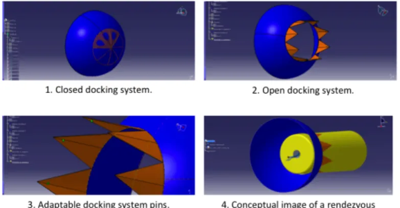
Paper [4] presents the detailed design methodology, mock-up building and verification results. Two main configurations have been studied and compared: adaptable pins docking system (Figure 9) and an inflatable docking system (Figure 10). Constraints relative to the structural perspective have been deeply analyzed thanking into account the different working environments during Thor space station lifetime (Launch, LEO, transfer and EML2) [17].
Figure 9: Adaptable pins docking system [17]
Figure 10: Inflatable docking system [17] III. MISSION LIFE-PROFILE
The following legs compose the space part of the mission life profile:
- Launch
- Station keeping in LEO
- Rendez-vous in LEO
- Transfer
- Station keeping at EML2
- Rendez-vous at EML2
- Docking at EML2
- Undocking
- Return to Earth
- Disposal
Most of the legs will be repeated several times so as to assemble the Thor space station, to deliver cargo or to transport crew from the Earth to EML2 and return. Figure 11 depicts one option of scenarios decomposition.
Figure 11: Example of mission scenario III.I Launch
Launch phase starts from the lift-off and finishes with the injection on orbit. Bibliographical analysis [18] led to the conclusion that a nominal LEO altitude could be 200 km, in the Sun-Earth plane. As each module maximal mass is limited to 20t, it can be launched by Ariane 5 as ATV. But a better option could be to leave Earth on-board a heavy lift vehicle, like SLS
(Space Launch System, under development), that should be able to deliver between 70t and 140t in LEO [19]. The lower configuration could deliver three modules and a sphere together.
III.II LEO station keeping
If the Thor station assembly occurs in LEO, it means that first modules will have to wait there until the arrival of the last modules to be integrated. At an altitude of 200km, the disturbances torques, and particularly the atmospheric drag, are quite high. As a consequence, the module orbit should be rapidly degraded. Station-keeping manoeuvres should be scheduled to maintain the orbital parameters.
The study presented in [18] demonstrated that a good angular position for a departure from LEO to inject the cargo in the Sun-Earth manifold is around 330°, on the opposite Sun side (see Figure 12) in the direction of the first Sun-Earth Lagrangian
point SEL1 (Sun-Earth Lagrangian point). It will permit the
connection to the fastest transfer trajectories.
Figure 12: LEO starting points for injection in the WSB III.I Rendez-vous in LEO
One option is to integrate the Thor space station in LEO. Thanks to the ISS lessons learnt, rendez-vous in LEO is a well-known process. Several maneuvers are required to adapt phase and attitude of both elements involved in the rendez-vous. The necessary delta-v to perform a rendez-vous can be estimated between 50 m/s and 100m/s [20].
III.I Transfer from LEO to EML2
As far as transfer strategy is concerned, a wide literature already exists and enlightens that four main strategies are possible: the direct transfer, the indirect transfer, the lunar fly-by and the Weak Stability Boundary (WSB) transfer.
Direct transfer consists in transferring a spacecraft between two space bodies with two direct ballistic maneuvers. It is the most fuel-consuming strategy since it does not take benefit of the manifolds. The indirect transfer strategy main goal is to deposit the spacecraft at an optimized point to enter the manifold and let it glide until the Halo orbit. In the Lunar fly-by strategy, the manifold entrance point is in the Moon vicinity so as to its slingshot effect to get into the manifold towards the Halo orbit. The Weak Stability Boundary transfer strategy is an extension of the CR3BP to two patched Three-Body problems to account for the influence of the Sun, Earth and the Moon.
Papers [11] and [18] provides methodology and results for transfer in the case of resupply cargo and crew vehicle transfer for a LEO to Halo orbit at EML2. Figure 13 sums up the cargo transfer strategy.
Figure 13: Transfer trajectory definition [18]
For cargo mission, optimal transfer strategy consists in WSB, while the best trajectory is find with a lunar flyby for crew rotation
III.II Station-keeping at EML2
A large variety of station-keeping strategies have previously been investigated [21], most notably for applications in the Sun-Earth system where the perturbations are small and can be corrected with less than 5 m/s/year [12]. Few studies consider trajectories near the Earth-Moon liberation points. In this case, delta-v budge is less than 25 m/s/year with a maneuver frequency of at least once every seven days [21]. For Earth-Moon applications, orbit maintenance is more challenging than in the Sun-Earth system because of shorter time scales, larger orbital eccentricity, Sun influence on the gravitational field and solar radiation pressure [22].
Figure 14 compares Halo orbit model (Farquhar model (red plot)
and Richardson model (blue plot)), for Az = 30000 km and m=3.
The green star in the center is EML2. It shows that if the mission requires that the Thor station is maintained on the ideal Halo orbit, station-keeping maneuvers will be mandatory.
Figure 14: Comparison of Halo obtained with Farquhar model and Richardson model [11]
III.III Rendez-vous in EML2
Whatever the Thor integration strategy is (assembly in LEO or anywhere else), rendez-vous in EML2 leg is mandatory for module integration, cargo delivery and crew rotation. Paper [11] proposes a rendez-vous strategy, based on a Halo to halo heteroclinic connection. Depending on the rendez-vous conditions, delta-v budget is [0.0025;4.5] km/s. As discrepancy is very high, study assumptions must be carefully managed.
−0.2 −0.15 −0.1 −0.05 0 0.05 0.1 0.15 0.2 −0.1 −0.05 0 0.05 0.1 0.15 X (x 105 km) Y (x 10 5 km) Az = 5000 km Az = 8000 km Az = 30 000 km Earth SEL2 SEL1 −0.3 −0.2 −0.100.1 −0.8 −0.6 −0.4 −0.2 0 0.2 0.4 0.6 0.8 −0.3 −0.2 −0.1 0 0.1 0.2 0.3 0.4 0.5 X Comparison of Halo orbit compution
Y
Z
Halo computed with Richardson Halo computed with Farquhar
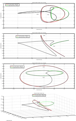
Figure 15 illustrates this initial guess trajectory for rendez-vous between the cargo and Thor.
Figure 15: Initial guess rendez-vous trajectory [11] III.IV Docking at EML2, Undocking and Disposal
The rendez-vous leg stops at a low relative distance between the cargo or the crew vehicle and the Thor space station. The distance is selected so that the relative motion can be linearized, but ensure safety criteria to avoid collision risks. Docking leg is the last step of the rendez-vous starting from the station keeping point to the physical contact of both elements. Undocking leg is the opposite step when the element is removed from the station and starts to leave its vicinity. Disposal stage is the last phase of the Thor space station life-profile. The station has to liberate the EML2 vicinity. A final boost can be burned so as to send it on an escape trajectory, on an unstable manifold.
Even if docking, undocking and disposal leg are mandatory and require delta-v,.
III.V Return to Earth
Until this point, only Earth-to-Moon trajectories have been discussed, and not the wayback. The return trajectories from the Halo orbit around EML2 to LEO can use exactly the same trajectories as described previously. Actually, if only the Earth-Moon-spacecraft three-body problem is considered, the theorem
of image trajectories [23] can be applied. This theorem states that if a trajectory is feasible in the Earth-Moon system, its image relatively to the plane containing the Earth-Moon axis and orthogonal to the plane of rotation of the Moon around Earth is also feasible if own in the opposite direction.
IV. DELTA-V BUDGET RESULTS
Finding the best strategy for the global mission from Space station deployment to the ends of resupply operations, means to determine the optimal scenario. It will be the one that minimizes the total delta-v during the operations (except disposal). Duration is a very important criterion for mission scenarios optimization. It has been taken into account in local optimization (transfer and rendez-vous legs). But the global mission optimization focuses on the delta-v.
III.VI Mission scenarios baseline
The baseline scenario is described as follows:
- Operational life-time duration, after station assembly:
15 years
- One crew rotation every 6 months
- One cargo delivery every 3 months
- Thor station total mass: 160t
- Thor Halo orbit Az: 8000km
- Thor Halo orbit family, m:3
- Cargo/ crew vehicle initial orbit Az: 7500km
- Cargo/ crew family, m:3
- LEO altitude: 200km
The last design parameter to be discussed is the Thor assembly strategy. Assembly of the seven cylindrical modules and two spheres can take place:
- In LEO, before sending them all together to EML2
- At EML2, after sending one by one to EML2
- Partially in LEO (two by two, or by three…) before
sending them by grape to EML2
- At EML1, before sending the station in EML2
The last option is not envisaged for the next steps of the study, but could be developed in a further analysis.
III.I Delta-v computation
As to compare the possible scenarios, the cost function is computed as follows
Δ𝑣!"! = Δ𝑣!"#$%!+ Δ𝑣!"#+ Δ𝑣!"#$%&'"+ Δ𝑣!"#$%+ Δ𝑣!"#$ Where :
- Δ𝑣!"#$%! is the delta-v for the SLS launches - Δ𝑣!"# is the delta-v for the rendez-vous in LEO - Δ𝑣!"#$%&'"is the delta-v for Station modules transfer
- Δ𝑣!"#$% is the delta-v for all the cargo encompassing launch, LEO station-keeping, transfer, rendez-vous in EML2 and return
- Δ𝑣!"#$ is the delta-v for all the crew trips
encompassing launch, LEO station-keeping, transfer, rendez-vous in EML2 and return without re-entry.
0.95 1 1.05 1.1 1.15 1.2 −0.2 −0.15 −0.1 −0.05 0 0.05 0.1 0.15 X (adimensionnal) Y (adimensionnal)
Cargo and station rendez−vous in XY plane Thor halo orbit(Az = 30000 km)
Cargo Halo orbit (Az = 8000 km)
THOR Cargo 0.95 1 1.05 1.1 1.15 1.2 −0.12 −0.1 −0.08 −0.06 −0.04 −0.02 0 0.02 0.04 0.06 0.08 X (adimensionnal) Z (adimensionnal)
Cargo and station rendez−vous in XZ plane
Thor halo orbit(Az = 30000 km) Cargo Halo orbit (Az = 8000 km)
THOR Cargo −0.2 −0.15 −0.1 −0.05 0 0.05 0.1 0.15 −0.12 −0.1 −0.08 −0.06 −0.04 −0.02 0 0.02 0.04 0.06 0.08 Y (adimensionnal) Z (adimensionnal)
Cargo and station rendez−vous in YZ plane
Thor halo orbit(Az = 30000 km)
Cargo Halo orbit (Az = 8000 km) THOR
Cargo 0.95 1 1.05 1.1 1.15 1.2 1.25 −0.2 −0.15 −0.1 −0.05 0 0.05 0.1 0.15 0.2 −0.15 −0.1 −0.05 0 0.05 0.1 X (adimensionnal) Cargo and station rendez−vous
Y (adimensionnal)
Z (adimensionnal)
Thor halo orbit(Az = 30000 km) Cargo Halo orbit (Az = 8000 km)
THOR
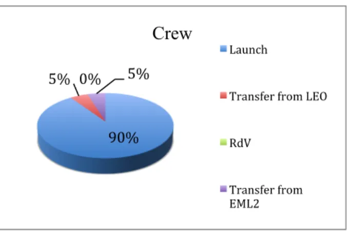
As launch cost surpasses and crushes all the other delta-v, it will not be taken into account for the scenarios comparison.
Figure 16: Crew rotation costs distribution
The delta-v of the cargo and crew vehicle does not depend on the scenario type. Results are: 210 km/s for two crew rotations per year and 390 km/s for the cargo during the mission lifetime. For station deployment, since the most expensive leg is the transfer, the best scenario is the one that minimizes the number of transfers. As a consequence, with a delta-v of 3.8 km/s, the optimal scenario is to integrate all the modules in LEO and transfer the station to EML2 through WSB.
The LEP assembly scenario advantages are:
- To ensure rendez-vous critical operations since
operators will continuously monitor the activities
- To ease a module replacement in case of failure
This scenario drawbacks are:
- To increase the LEO activities duration. By
consequence, the modules will be longer exposed to LEO environment.
- To require LEO station keeping maneuvers
- To postpone Thor station delivery in EML2.
V. CONCLUSION
This paper presented the optimization of the scenarios to deploy and operate an inhabited space station, named Thor, in Earth – Moon Lagrangian point vicinity. The design process of the station leads to the conclusion that the station could be composed of seven cylindrical and two spherical modules, so as to comply functional architecture and habitability requirements. Designed to welcome at least six astronauts, the station offers medical services to other exploration crews and technical support for science and exploration robotic missions. Mission analysis recommends locating the space station on a Halo orbit, with a maximal elongation of 8000km along the z-axis around EML2. Resupply cargo transfers should be performed thanks to a WSB strategy, while crew vehicle should follow lunar flyby trajectories.
On mission analysis side, the next step of the Thor project is to improve the transfer and rendez-vous strategies optimization, so as to take into account the Sun influence on the gravitational
field. The station design will go one with the propulsion subsystem improvement.
This project mainly concludes that the Lagrangian point vicinity is a promising location for Human spaceflight as a gateway for scientific and exploration mission.
I. REFERENCES
[1] – ISECG Global Exploration Roadmap, August 2013 [2] – S. Koon, M. W. Lo, J. E. Marsden, and D. R. Shane,
Dynamical Systems, the Three-Body Problem and Space Mission Design. Marsden Books, 2008.
[3] –Stéphanie Lizy-Destrez, C. Blank, Mission analysis for a
Space Medical Center of an exploration gateway at a lunar libration point, IAC-11.A5.4.8 - IAC 2011 - 3- 7 October 2011
Cape Town - South Africa
[4] – Crescenzio Ruben Xavier Amendola, Stéphanie Lizy-Destrez, Régine Leconte, The THOR space station at EML2:
analysis and preliminary design of an innovative adaptive docking system, IAC-14, C2.1x21593,
[5] – Farquhar, R. W. Station-keeping in the vicinity of collinear
libration points with an application to a Lunar communications problem, in Space Flight Mechanics, Science and Technology
Series, volume 11, pages 519-535, American Astronautical Society, New York
[6] – Farquhar, R. W, The flight of ISEE-3/ICE: origins, mission
history and a legacy, The Journal of Guidance and Control 4,
192-196, 2001
[7] – Farquhar, Robert W. A Halo-Orbit Lunar Station. Astronautics and Aeronautics. 1972, pp. 59 - 63.
[8] – Howell, K.C. Families of Orbits in the Vicinity of the
Collinear Libration Points. The Journal of the Astronautical
Sciences. 2001, Vol. 49, 1, pp. 107 - 125.
[9] – Howell, K.C, et al. Representations of Invariant Manifolds
for Applications in Three-Body Systems. The Journal of the
Astronautical Sciences. 2006, Vol. 54, 1
[10] – Lagrange J-L, Essai sur le problème des trois corps, 1772. Prix de l’Académie Royale des Sciences de Paris, tome IX, in vol. 6 of Oeuvres de Lagrange (Gauthier-Villars, Paris, 1873), 272-282
[11] – Stephanie Lizy-Destrez, Bastien Le Bihan, Mohammad Iranmanesh, Transfer and rendez-vous for the deployment and
the servicing of an inhabited space station at Earth-Moon L2,
IAC-14, C1.8.10
[12] – R. W. Farquhar, The utilization of Halo Orbits in
Advanced Lunar Operations, Tech. Rep. X-551-70-449, NASA,
Goddard Space Flight Center, December.
[13] – Stéphanie Lizy-Destrez, Giuseppe Ferraioli, Chloé Audas, Jason Piat, How to save delta-V and time for a round trip to
EML2 Lagrangian point? IAC-12.A5.4.12, - IAC 2012 - 1-5
October 2012 Naples – Italy
[14] - L.M. Jagger, Spacecraft Architectural Design with
Minimal Artificial Weightness Concept, Cranfield University
College of Aeronautics, ENSICA, (1998).
[15] - Giuseppe Ferraioli, Dr. Mickael Causse, Stephanie Lizy-Destrez, Prof. Yves Gourinat, Habitability of manned vehicles :
the impact of human factors on future long duration human space exploration missions en route to Mars, IAC-13, A1.1.1
90% 5% 0% 5%
Crew
Launch
Transfer from LEO RdV
Transfer from EML2
[16] - Ariane space service & solutions, Ariane 5 -User’s
manual, issue 5 Revision 1, July 2011.
[17] - Amendola C. R. X., Lizy-Destrez S., Panorama of ideas
on structure and materials for the design of a multi-modular space station at EML2 . IAC-13,D3.1,6x17742, 2013.
[18] - Bastien Le Bihan, Pierre Kokou, Stephanie Lizy-Destrez,
Computing an optimized trajectory between Earth and an EML2 halo orbit, SciTech 2014, National Harbor, MD, 13-17 Jan 14
[19] - Chris Gebhardt, "SLS: NASA identifies DAC-1
configuration candidates for wind tunnel tests"
[20] – M. Augelli, P. Benarroche, M. Vanhove, ATV
Operations: from Demo Flight to Human Spaceflight Partner,
SpaceOps 2014 conference, 5-9 May 2014, Pasadena, CA [21] – K. Howell et al., Station-keeping of Lissajous
Trajectories in the Earth-Moon System with Applications to ARTEMIS, 20th AAS/AIAA Space Flight Mechanics Meeting,
San Diego, California, February 2010.
[22] – M. Ghorbani and N. Assadian, Optimal station-keeping
near Earth-Moon collinear libration points using continuous and impulsive manoeuvres, Advances in Space Research,
Volume 52, Issue 12, Pages 2067-2079, 2013.
[23] – A. Miele, Theorem of image trajectories in the

![Figure 7: Thor modules internal configuration [13]](https://thumb-eu.123doks.com/thumbv2/123doknet/3287243.94309/5.918.485.876.416.579/figure-thor-modules-internal-configuration.webp)