HAL Id: hal-02491504
https://hal.archives-ouvertes.fr/hal-02491504
Submitted on 26 Feb 2020
HAL is a multi-disciplinary open access
archive for the deposit and dissemination of
sci-entific research documents, whether they are
pub-lished or not. The documents may come from
teaching and research institutions in France or
abroad, or from public or private research centers.
L’archive ouverte pluridisciplinaire HAL, est
destinée au dépôt et à la diffusion de documents
scientifiques de niveau recherche, publiés ou non,
émanant des établissements d’enseignement et de
recherche français ou étrangers, des laboratoires
publics ou privés.
Development of a reactor for the in situ monitoring of
2D materials growth on liquid metal catalysts, using
synchrotron X-ray scattering, Raman spectroscopy, and
optical microscopy
Mehdi Saedi, J de Voogd, A Sjardin, A Manikas, C Galiotis, M Jankowski,
Gilles Renaud, F Porta, O Konovalov, G van Baarle, et al.
To cite this version:
Mehdi Saedi, J de Voogd, A Sjardin, A Manikas, C Galiotis, et al.. Development of a reactor for the in
situ monitoring of 2D materials growth on liquid metal catalysts, using synchrotron X-ray scattering,
Raman spectroscopy, and optical microscopy. Review of Scientific Instruments, American Institute of
Physics, In press, �10.1063/1.5110656�. �hal-02491504�
Development of a reactor for the in situ
monitoring of 2D materials growth on liquid metal
catalysts, using synchrotron X-ray scattering,
Raman spectroscopy, and optical microscopy
Mehdi Saedi *1, J.M. de Voogd *2 , A. Sjardin 2, A. Manikas 3, C. Galiotis 3,4, M. Jankowski 5, G. Renaud 5, F. La Porta 6, O. Konovalov 6, G.J.C. van Baarle ‡2, I.M.N. Groot †1
* Both authors share the first authorship
† Corresponding author for the scientific inquiries, Email: i.m.n.groot@lic.leidenuniv.nl
‡ Corresponding author for the technical inquiries, Email: baarlelpm@leidenprobemicroscopy.com 1 Catalysis & Surface Chemistry (CASC), Leiden Institute of Chemistry (LIC), Leiden University, Einsteinweg 55, 2333 CC Leiden, The Netherlands
2 Leiden Probe Microscopy (LPM), Kenauweg 21, 2331 BA Leiden, The Netherlands
3 Nanotechnology and Advanced Materials Laboratory (NANOTECH), Department of Chemical Engineering, University of Patras, 26504 Rio Achaia, Patras, Greece
4 Institute of Chemical Engineering Sciences (ICE-HT), Foundations for Research and Technology-Hellas (FORTH), Stadiou Str., Platani, 26504 Patras, Greece
5 University Grenoble Alpes, CEA, IRIG-DEPHY-MEM, 17 Avenue des Martyrs, 38000 Grenoble, France 6 ID10, European Synchrotron Radiation Facility (ESRF), 71 Avenue des Martyrs, 38000 Grenoble, France
hor’s peer reviewed, accepted manuscript. Howe
ver, the online
version of record will be different
from this
version
once it has bee
n copyedited an
d
typeset.
PLEASE CIT
E THIS ARTI
C
LE AS DOI:
10.1063/1.5110656
Abstract
Liquid metal catalysts (LMCats) (e.g. molten copper) can provide a new mass-production method for two-dimensional materials (2DMs) (e.g. graphene) with significantly higher quality and speed, and lower energy and material consumption. To reach such technological excellence, the physicochemical properties of LMCats, and the growth mechanisms of 2DMs on LMCats should be investigated. Here we report the development of a CVD reactor which allows the investigation of ongoing chemical reactions on the surface of a molten metal at elevated temperatures and under reactive conditions. The surface of the molten metal is monitored simultaneously using synchrotron X-ray scattering, Raman
spectroscopy, and optical microscopy, thereby providing complementary information about the atomic structure and chemical state of the surface. To enable in situ characterization on a molten substrate at high temperatures (e.g. ~1370 K for copper), the optical and X-rays windows need to be protected from the evaporating LMCat, reaction products, and intense heat. This has been achieved by creating specific gas-flow patterns inside the reactor. The optimized design of the reactor has been achieved using multi-physics COMSOL simulations, which take into account the heat transfer, fluid dynamics, and transport of LMCat vapor inside the reactor. The setup has been successfully tested and is currently used to investigate the chemical vapor deposition (CVD) growth of graphene on the surface of molten copper under pressures ranging from medium vacuum up to atmospheric pressure.
1. Introduction
For nanomaterials to have a significant technological impact, efficient production, assembly and maintenance techniques must be developed to harvest their unique properties in ubiquitous applications and devices. 2D materials (2DMs), having only one of their dimensions confined at the nanoscale, are expected to be the easiest class of nanomaterials to manipulate and process in a number of technological applications as compared to 1D or 0D derivatives. Yet, mass production of high-quality 2DMs proves to be a formidable challenge by itself, attested by the number of publications on this topic and the difficulties of scaling up.
The current state-of-the-art synthesis method of 2DMs involves the dissociative adsorption of gas-phase precursors on a solid catalyst. The most well-known example is the chemical vapor deposition (CVD) of graphene on a copper surface at elevated temperatures (~1270 K) using a CH4 precursor [1]. The fabrication process is rather slow, as it involves multiple steps for substrate preparation, 2DM growth, its separation from the catalyst, and its transfer to a target substrate. Producing a high-quality 2DM layer is also often a challenge, as natural imperfections of a solid surface – such as crystalline anisotropies, surface roughness, and structural defects such as grain boundaries or dislocations – can induce defects in the overgrown 2DM. 2DMs can nucleate at multiple points on the surface, each
hor’s peer reviewed, accepted manuscript. Howe
ver, the online
version of record will be different
from this
version
once it has bee
n copyedited an
d
typeset.
PLEASE CIT
E THIS ARTI
C
LE AS DOI:
10.1063/1.5110656
having a different crystalline direction [1]. Upon their coalescence, neighbor domains cannot rotate freely and match their crystalline direction, as they are strongly anchored to the solid surface. This leads to a multi-domain 2DM structure with typical domain sizes in the order of micrometers. Upon cooling down from high temperatures (needed for 2Dm growth) to ambient temperature, the thermal expansion mismatch between the 2DM and the substrate
results in the creation of a highly wrinkled
2DM that normally contains flat islands separated by a network of folds [1,2].
The separation and transfer steps add additional bottle necks in the production process. For the case of graphene for example, due to extremely high adhesion and friction forces between 2DM and the solid catalyst, it is virtually impossible to directly peel the graphene layer off the solid catalyst surface without destroying it. One common separation method is to first add a backing layer on the 2DM and then etch the catalyst away chemically [3]. This leads to the loss of the metal catalyst, significant waste production, and further damage and contamination of the 2DM. Therefore the overall process is slow, inefficient, expensive, and environmentally unfriendly.Of the above mentioned problems, the solid state of the substrate seems to be the common source. By taking a radical approach of synthesizing 2DMs on a liquid metal catalyst (LMCat), one can potentially bypass or reduce these problems at once [4]. The surface of a liquid phase provides the most isotropic, defect free, and smooth substrate to grow 2DMs on. The dynamic nature of the liquid surface can provide more efficient defect healing during the 2DM growth. Furthermore, the viscous forces on the liquid surface are orders of magnitude less than the frictional forces on a solid. Hence, the nucleated 2DM domains have the possibility to move, rotate and annihilate their boundary faults upon their coalescence.
Elimination of surface frictional forces and the free mobility of 2DMs on LMCats opens an important possibility, namely direct separation of the 2DM from the liquid substrate [5]. For example, the mechanical strength of graphene is significantly higher than the force needed to shear and directly separate it from the molten copper. To our knowledge the work of adhesion of graphene on molten copper is not reported, but one would expect it to be reasonably close to the one of graphite on molten copper, which is 0.3 J·m-2 at 1373 K [6]. This translates to 0.3 N·m-1 force per unit length needed to separate the graphene from molten copper. On the other hand, the mechanical tensile strength of defect-free graphene at 1373 K is predicted to be 20.7 N·m-1 [7]. Introduction of domain boundaries can reduce graphene’s strength to ~35% of the pristine one [8]. So even if one assumes the formation of domain boundaries in graphene on LMCat, graphene’s strength is estimated to be at least ~7.2 N·m -1, which is still ~24 times larger than the force needed to separate it directly from the molten copper.
The possibility of direct 2DM separation inspires a potential continuous 2DM production scheme, where a 2DM domain grows from one side by an ongoing CVD reaction on an LMCat, while being separated from the LMCat surface from the other side. By using LMCat technology for continuous 2DM synthesis, the time-consuming steps of substrate preparation, separation, and transfer can be bypassed all at
hor’s peer reviewed, accepted manuscript. Howe
ver, the online
version of record will be different
from this
version
once it has bee
n copyedited an
d
typeset.
PLEASE CIT
E THIS ARTI
C
LE AS DOI:
10.1063/1.5110656
once. Such a process would have the potential to produce a low-defect single-domain 2DM with virtually unlimited length, while the catalyst metal is being reused and not wasted.
Realization of such a technologically demanding process, however, requires detailed knowledge of LMCat catalytic properties and 2DM growth mechanisms on LMCats. Furthermore, controlling such a delicate process requires the development of dedicated instrumentation and methodology capable of in situ detection and monitoring of the 2DM growth on an LMCat, under high-temperature and reactive CVD conditions.
While to the best of our knowledge the idea of continuous 2DM production on an LMCat has never been proposed before, the feasibility of growing 2DMs on LMCats has already been proven. In 2012, Feng et al. demonstrated graphene growth on molten copper and found the produced graphene to be a perfect single domain [9]. Soon after, the feasibility of graphene growth on other LMCats including molten Ga, In, and Sn was also reported [10,11]. Recently, LMCats were also successfully utilized to synthesize other 2DMs such as germanene [12]. These studies have demonstrated a myriad of 2DM morphologies and growth modes depending on the reaction parameters, whose complex nucleation, growth, and etching kinetics of 2DMs on an LMCat are poorly understood [13,14]. Several models have been proposed to explain the experimental observations. However, the proposed mechanisms are often based on uncertain assumptions, and sometimes contradicting with each other. The origin of this problem is twofold:
1) At the moment there are no experimental facilities nor methods available to study the formation of 2DMs on LMCats in situ at high temperatures (T > 1000 K). In the experiments done so far, after exposing the LMCats to the 2DM growth conditions in a furnace, the samples were cooled down to room temperature (taking 10s to 100s of minutes) and then studied using standard microscopy or spectroscopy techniques. Obtaining an understanding of the active atomic-scale mechanisms on LMCats at the growth conditions from such ex situ data obtained from the solidified sample at room temperature can be problematic, if not misleading.
2) For traditional catalytic chemical reactions two fundamental design rules apply: Minimize the energy consumption of the process and maximize the catalyst surface-to-volume ratio to maximize the
reaction output. In contrast, in the case of LMCats, a significant amount of heat is needed to melt and keep the catalyst in liquid form, and a liquid catalyst tends to minimize its surface-to-volume ratio due to surface-tension effects. Hence, for traditional chemical reactions, LMCats had no promising
commercial prospects, leading to the lack of motivation for investigating their catalytic properties from a fundamental point-of-view. Accordingly, the current knowledge about the catalytic activity of LMCats is rather scarce, and mostly limited to some preliminary studies from before 1985 [15].
As discussed however, special properties of LMCats can open a new paradigm for the mass production of high quality 2DMs. To reach such a technological excellence, bridging two major scientific unknowns
hor’s peer reviewed, accepted manuscript. Howe
ver, the online
version of record will be different
from this
version
once it has bee
n copyedited an
d
typeset.
PLEASE CIT
E THIS ARTI
C
LE AS DOI:
10.1063/1.5110656
is of crucial importance: 1) precise knowledge of the mechanism, thermodynamics, and kinetics of nucleation and growth of 2DMs on LMCats, and catalytic properties of LMCats, specifically in relation to the formation of 2DM on the surface and the interactions between the fluid catalyst and the formed products. Here we report the development of instrumentation and methodology capable of studying the ongoing chemical reactions on the molten catalyst, with the goal to open two new lines of research, namely in situ investigations on the catalytic activity of LMCats, and more specifically, unraveling the growth mechanisms of 2DMs on LMCat surfaces. This knowledge is key to exploit the unique properties of 2DMs on the industrial scale and in every day devices via the LMCat technology proposed here.
2. Experimental methodology
As starting point for our investigation, we set our goal on in situ study of graphene formation on molten copper. This is one of the most studied 2DM formation processes (ex situ) to this day, for which there have been several reports showing its general feasibility [9,16]. The choice is further motivated by the fact that the solubility of carbon in molten copper is very low (~0.0001 wt% carbon at 1370 K) [17], and the vapor pressure of molten copper has one of the lowest values (~0.07 Pa at 1370 K) compared to other LMCats at the high temperatures relevant for graphene growth. Once the
graphene/molten copper system has been investigated properly, exploring other LMCats such as Sn, In, and Ga will be a natural follow-up. Our experiments aim to obtain in situ information about
nucleation and growth of 2DMs as well as the atomic structure and chemical composition of the LMCat surface before the exposure to the precursor gases, during the growth of the 2DM, and during the cool-down phase. Due to the limited mean free path of electrons in the high gas-pressure conditions of the CVD process (medium vacuum to atmospheric pressure), the photon-based characterization techniques of Raman spectroscopy and surface X-ray scattering have been chosen as complementary methods to investigate simultaneously the 2DM formation on LMCats.
2.1. In situ Raman spectroscopy
To study the catalytic properties of LMCats and the formation of 2DMs, the availability of a chemically-sensitive technique capable of detecting molecules and chemical bonds is of crucial importance. Among the optical techniques, Raman spectroscopy has been used extensively for studying nanomaterials in general and graphene (on solid substrates) in particular [18]. This technique is sensitive to detect the traces of the precursor adsorbates, intermediate reaction species, and characteristics of final 2DM products on the LMCat surface, including number of layers, stacking type, defect density, and presence
hor’s peer reviewed, accepted manuscript. Howe
ver, the online
version of record will be different
from this
version
once it has bee
n copyedited an
d
typeset.
PLEASE CIT
E THIS ARTI
C
LE AS DOI:
10.1063/1.5110656
of doping or contamination. Moreover, Raman spectroscopy can provide information about the shape evolution of the 2DM domains and the growth speed of domain boundaries, and distribution of chemical compounds on the surface with a spatial resolution in the order of a few hundreds of nanometers. In combination with isotope signaling, in situ Raman spectroscopy can provide deeper insight into 2DM nucleation and growth mechanisms [16].
However, performing in situ Raman spectroscopy at high temperatures (T > 1000 K) needs special considerations, otherwise the weak Raman signal could be easily swarmed by the intense thermal radiation of the molten surface. This challenge could be tackled by a number of experimental solutions such as a) spatial filtering provided by confocal optics to block the background thermal radiation of surface regions surrounding the focal (laser) spot [20], b) using laser sources with higher frequencies to shift the Raman-scattered light further away from the thermal radiation spectrum [21], c) utilizing the anti-Stokes scattering signal, the intensity of which becomes stronger at higher temperatures due to the higher occupancy of the 2DM vibrational states [22], and d) utilizing multi-photon approaches which can increase the efficiency and hence the intensity of the Raman signal significantly [23]. This can provide the opportunity of using lower input power (preventing beam damage on 2DMs),
overcoming detector noise, and increasing the imaging speed for known substances. As will be presented later, by implementing some of the above-mentioned measures, Raman experiments have been performed successfully on samples with temperatures up to 2200 K [24,25], and on graphene on SiO2 substrates up to 1450 K [26].
2.2. In situ surface X-ray techniques
Obtaining knowledge about the atomic structure of the growing 2DM flakes and of the LMCat surface during the 2DM growth is of critical importance. It is known that differences in surface tension of melt constituents can cause segregation and formation of surface phases that would have a radically different composition compared to the liquid bulk [27,28]. Growing 2DM flakes is expected to influence the underlying LMCat structure by dictating their order onto it. The order is expected to extend outside of the flakes, possibly influencing the lateral growth of the flakes and even giving rise to interactions between neighboring flakes. LMCat-mediated interaction is thus one of the potential mechanisms that can explain the observed self-ordering patterns between separated graphene flakes grown on molten copper [7]. Thermal capillary waves are induced by thermal fluctuation at the molecular scale on the phase boundary of a fluid, whose dynamics are dominated by the surface tension [27,28]. The existence of a 2DM on the surface is expected to change or suppress the capillary-wave spectrum on the melt. The capillary waves, on the other hand, induce a certain effective roughness on the liquid surface, which in turn can influence the catalytic activity of the molten phase. The extent of mutual influence between 2DM, thermal capillary waves, and catalytic activity of the LMCats and its consequences for the 2DM growth is presently completely unknown.
hor’s peer reviewed, accepted manuscript. Howe
ver, the online
version of record will be different
from this
version
once it has bee
n copyedited an
d
typeset.
PLEASE CIT
E THIS ARTI
C
LE AS DOI:
10.1063/1.5110656
Our aim is to investigate these effects using surface-sensitive techniques including X-ray reflectivity (XRR), grazing-incidence X-ray diffraction (GIXD). XRR can probe the liquid electron density profile in out-of-plane direction to the surface, with potential evidence of density oscillations, i.e. our-of-plane layering (which might be correlated to the growing 2DM flakes) as well as the van der Waals gap between the 2DM and the LMCat. GIXD, on the other hand, can provide information on short-range order in the liquid, both parallel and perpendicular to the surface. GIXD can be used to resolve 2DM diffraction rods, whose quantitative measurements can provide the detailed atomic structures in the flakes of the 2DM [29]. The experiments have to be performed under grazing incidence, possibly below the critical angle for total external reflection of X-rays, in order to enhance surface to buck signal ratio. X-ray scattering techniques have already been used to investigate adsorbed organic molecules on the surface of water or mercury at room temperature [30,31], as well as, on the surface structure of the binary liquid Au-Si alloy system at temperatures up to 650 K [32]. These techniques have also been successfully used to study the structure of graphene grown on solid catalytic substrates [33,34].
For successful x‐ray experiments the surface of molten copper should be close to flat, e.g. a large radius of curvature, so that the incident x-rays have a well-defined incident angle on the sample. However, molten copper may not wet an untreated flat tungsten substrates and the copper foils may break into small droplets when heated above the melting temperature. A possible way to make the copper film flatter is to roughen the tungsten substrate. This decreases the contact angle of molten copper via Wenzel's equation cos(θ*) = r cos(θ), where θ* and θ are the contact angle on substrate after and before roughening, and r is the roughness ratio.
2.3. Instrumentation requirements
To perform the above-mentioned in situ X-ray and Raman experiments, the first step is to develop customized instrumentation, capable of studying the 2DM formation process on the surface of LMCats. Both in situ experiments need several common features: gas mixing and analyzing system, controlling units for the reactor including heating, cooling, etc. To guarantee the reproducibility of exact 2DM growth conditions for both Raman and X-ray experiments we have integrated both techniques in one LMCat reactor. This provides the possibility of simultaneous in situ Raman and X-ray experiments, and direct comparison of the results. For the design and fabrication of such a novel instrument, several technical challenges needed to be addressed:
1. The surface of the liquid metal should be as undisturbed as possible. This is especially important for X-ray measurements where a precise definition of the incident beam on the liquid surface is needed. One potential source of liquid-surface disturbance is the convective currents in the LMCat. Therefore, the heating mechanism inside the reactor has to be designed to minimize these currents at the X-ray beam or Raman laser incident points. The X-ray scattering experiments on a liquid phase need a customized diffractometer capable of keeping the liquid sample horizontal and fixed in position during the X-ray scans, to avoid surface-wave formation on the liquid. Our LMCat reactor is designed to be
hor’s peer reviewed, accepted manuscript. Howe
ver, the online
version of record will be different
from this
version
once it has bee
n copyedited an
d
typeset.
PLEASE CIT
E THIS ARTI
C
LE AS DOI:
10.1063/1.5110656
compatible with liquid-phase diffractometers located at the ESRF-ID10 (in Grenoble, France), DESY-Petra III-P08 (in Hamburg, Germany), Diamond-I07 (in Oxfordshire, UK), and Soleil-SIRIUS/SIXS (in Saint-Aubin, France) synchrotron beamlines [35–37]. For X-ray measurements the reactor wall is often made of beryllium which has a high transmission in the X-ray range of electromagnetic spectra. As the reactor will be filled with CVD gases with different pressures, this can contribute to unwanted X-ray scattering and absorption. Therefor the maximum optimal distance between X-ray window (Be wall) and LMCat would be in the order of ~10 cm, assuming use of low (8keV) and high (24 keV) energy X-rays.
2. For the Raman measurements, a shorter distance between the objective lens and the sample would allow the use of an objective with higher numerical aperture. This leads to stronger collected Raman signal, shorter acquisition time, and higher spatial resolution. For room temperature measurements, an objective–sample distance in the order of 1.0 mm is desirable. However, having such a short distance is obviously not an option for studying a molten copper surface at 1370 K. I
n order to protect
the Raman system objective lens against the gasses in the reactor and the high temperature radiation
from the LMCat, we have chosen to have an optical window separating the lens and the inner reactor
environment.
The close distances between extremely hot LMCat and the fragile optical and X-ray windows might potentially leads to heat-shocks and fracture. To protect these windows an efficient cooling mechanism should be devised to keep the temperature preferably below ~400 K during in situ measurements.3. Rapid evaporation of the atoms from the LMCat surface can contribute to surface disturbance and the evaporated atoms can deposit on reactor windows and disturb the X-ray/Raman measurements. As mentioned, molten copper has one of the lowest vapor pressures compared to other liquid metals at temperatures relevant for graphene CVD growth. Nevertheless, copper evaporates at a rate of about 500 monolayers per second (~0.4 mm/hr) in vacuum at 1370 K. The deposited copper layer on the optical and X-ray windows can absorb the laser light/X-rays and eventually disrupt the in situ experiments. The optical window (normally quartz or sapphire) could be exchanged more regularly than the X-ray window, as the latter is far more expensive and cleaning might be a hazardous task. We have estimated the acceptable deposition rates on both the optical and X-ray windows to be ~1 pm/hr. This deposition rate is estimated to cause less than 10% absorption of laser light/X-rays passing through optical/X-ray windows during 2 weeks/20 years of continuous reactor service
respectively. To suppress the LMCat evaporation, a noble gas containing the 2DM-formation precursor mixture (e.g. CH4, H2) can be used to flow through the reactor. The presence of noble gas in the reactor 1) suppresses the evaporation of the LMCat, 2) slows down the diffusion of evaporated metal toward the windows [38,39], while 3) by inducing an optimized gas flow pattern in the reactor, evaporated atoms can be swept away by the flow of the carrier gas through the reactor before they can reach the optical windows, and 4) the gas flow can protect and cool down the reactor windows
hor’s peer reviewed, accepted manuscript. Howe
ver, the online
version of record will be different
from this
version
once it has bee
n copyedited an
d
typeset.
PLEASE CIT
E THIS ARTI
C
LE AS DOI:
10.1063/1.5110656
from overheating caused by convection of heated gas and radiation from LMCat. However, the gas flow over the LMCat surface should not be too strong to cause disturbance and surface waves on it.
A noble gas with heavier atomic mass can decrease the LMCat evaporation more efficiently [38], however, it would also interact with X-rays more strongly, increasing the unwanted X-ray absorption and scattering. We have selected argon as the reactor background gas for its average atomic mass and price. Setting the reactor total inner pressure to ~1 bar simplifies the reactor design requirements in comparison to a reactor with lower (high vacuum or lower) or higher inner pressures, i.e. more than 2 bar (all reported pressures values correspond to absolute pressures).
3. The reactor design
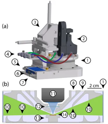
A schematic of the LMCat reactor is shown in Fig. 1. The reactor has a cylindrical shape with 150 mm inner diameter and 46 mm height. The reactor’s cylindrical wall is made of 0.5-mm-thick beryllium (No. 1 in Fig. 1), while the top and bottom parts are made of aluminum with copper water cooling pipe within.
Figure 1. Schematic of the LMCat reactor showing its outer (a), and inner cross section (b) structure. The components are 1. Cylindrical X-ray window, 2. Optical probe (here, a Raman probe with integrated video camera),
hor’s peer reviewed, accepted manuscript. Howe
ver, the online
version of record will be different
from this
version
once it has bee
n copyedited an
d
typeset.
PLEASE CIT
E THIS ARTI
C
LE AS DOI:
10.1063/1.5110656
3. X-Y-Z translation stage, 4. Gas lines in/out of reactor, 5. Pressure gauge, 6. Heater control unit with power input and thermocouple reading connections, 7. Water cooling inlet, 8. Gas inlet, 9. Gas outlet, 10. Flow deflectors, 11. Objective lens, 12. Optical window, 13. Heater, 14. LMCat sample. The blue and green areas in (b) are the optical
and X-ray passages between the windows towards the LMCat sample.
The custom heater assembly contains a resistive heater element and it is positioned at the center of the reactor (No. 13). The heater can provide temperatures exceeding ~1800 K. The sample holder consists of a tungsten disk, which is fixated by a clamping mechanism on the heater and is in direct contact with a thermocouple. Fresh copper samples can be added to the sample holder as ultra-pure foils (No. 14). The sample holder can be accessed by unscrewing the top plate of the reactor. The optical window for the Raman probe, is placed directly above the LMCat sample, allowing the Raman objective lens to be as close as 12.7 mm to the sample surface (No. 12).
A 30 mW violet solid-state laser (excitation wavelength of 405 nm) has been chosen for the Raman experiments in order to reduce the black body radiation effect. The laser is delivered to the Raman probe (No. 2) by means of an optical fiber cable. The probe is equipped with microscopic long-working-distance objectives (No. 11), and is mounted on a motorized XYZ positioning system (manipulator) over the reactor which can adjust the positioning of the Raman objective lens in the optical port within a range of 25.4 mm with ±2.5 µm accuracy (No. 3). As already mentioned, the 2DM/LMCat can also be investigated via the same optical port by other optical methods such as optical microscopy,
reflectometry, or pyrometry.
Extensive COMSOL Multiphysics simulations have been performed to optimize the reactor’s inner design and gas flow pattern. This is to satisfy the two design criteria, i.e. 1) minimize the deposition rate of Cu on the windows to below ~1 pm/hr, and 2) minimize the temperature of windows to below 400 K, while also minimizing the required gas inlet flux for window protection. A specially designed gas-flow pattern inside the reactor is used to redirect the hot and copper-rich gas, rising from the LMCat, and prohibits it to get in contact with the optical/X-ray windows.
For a specific heater temperature and inlet gas flow rates, coupled heat transfer and fluid dynamic COMSOL modules have been used to simulate the gas flow and temperature distribution in the reactor. To capture turbulent convection (due to the high temperature of the heater) and strong interactions of gas with the flow deflectors, the L-VEL turbulent model was used to describe the gas flow. The heat transfer calculations included conduction in the solids, convection in the gas, and radiation from the heater, while setting the water cooled top and bottom reactor plates to room temperature. After converging to a self-consistent solution, the stationary flow pattern was used to predict the transport of copper vapor rising from the LMCat surface in the reactor. The adsorption coefficient of copper vapor was set to 100% on the reactor walls and windows. From the concentration distribution of copper vapor in the reactor finally one can deduce the deposition rate of copper on the reactor's inner surfaces. The cylindrical symmetry of the reactor ensures a symmetric gas flow pattern, providing the possibility of uniform protection of optical/X-ray windows for the whole 360-degrees azimuthal angles. The gas in/outlets to the reactor in Fig. 1 (No. 8, 9) are hence ring-shaped openings, located on the top or bottom plates of the reactor. In the final design, special precautions have been taken to symmetrize
hor’s peer reviewed, accepted manuscript. Howe
ver, the online
version of record will be different
from this
version
once it has bee
n copyedited an
d
typeset.
PLEASE CIT
E THIS ARTI
C
LE AS DOI:
10.1063/1.5110656
the real gas flows as much as possible. A flow of gas mixture, containing the graphene growth precursors (CH4 and H2), enters the reactor via the gas inlet (No. 8), directed toward the optical window, see Fig. 2. The gas exits via a ring-shaped nozzle, and then funneling downward toward the LMCat sample, see Figs. 3a–b. The funneling region provides an optical cone of 45° between the objective lens and the LMCat sample. After passing over the LMCat, the gas exits the reactor via the gas outlet (No. 9).
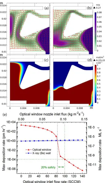
Figure 2. The optimized inner design of the LMCat reactor and simulated gas flow pattern in it. The figure shows half of the reactor’s cross section. The red arrows show the gas-flow direction, the color scale shows the gas velocity (m/s), and the dotted box outlines the zoomed-in area in Figure 3a–d. The simulation has assumed a flow
rate of 100 sccm for the optical window inlet, an outlet pressure of 1 bar, a heater temperature of 1370 K, and bottom and top plate temperatures of 293 K. The marked numbers correspond to entities described in Fig. 1b.
By having sufficient inlet-flow rate for the optical window, the window is only in contact with fresh gas, and hence is protected from the hot and copper-rich gas rising from the LMCat, see Figs. 3c–d. Figure 3e shows the predicted copper deposition rates on the optical window as a function of inlet-flow rate of the optical window. There is a sharp drop in the copper deposition rate on the optical window from about 80–90 sccm, which corresponds to a sharp transition in the gas flow pattern in the funneling region below the optical window (compare Figs. 3a and 3b). For having ~1.0 pm/hr copper deposition rate on the optical window, one would need ~85 sccm inlet-flow rate. We chose 100 sccm as a safe operational flow rate of the optical window, which includes a 20% safety factor, which leads to a predicted copper deposition rate of 1.15 × 10⁻⁴ pm/hr (1.51 × 10⁻¹⁰ monolayers per second) on the optical window. Higher inlet-flux values are not favorable as they increase the chance of the LMCat surface to be disturbed by the high-speed gas flow and increase the Ar consumption. The maximum temperature on the window is predicted to be 351 K, only 58 degrees warmer than the inlet gas temperature, mainly caused by the radiation from the LMCat, see supplementary material for more information about this. Hence our protection criteria for the optical window are well satisfied.
hor’s peer reviewed, accepted manuscript. Howe
ver, the online
version of record will be different
from this
version
once it has bee
n copyedited an
d
typeset.
PLEASE CIT
E THIS ARTI
C
LE AS DOI:
10.1063/1.5110656
Figure 3. The gas flow pattern and velocity in m/s (a–b), and copper vapor concentration in mole/m3 (c–d) near the
optical window (the outlined area in Fig 2) as a function of window gas inlet. The gas inlet-flow rates are, 60 sccm (a,c), 90 sccm (b,d). (e) shows the relation between the flow rate of the optical-window inlet and the maximum
deposition rates on the optical and X-ray windows, for the reactor design shown in Fig. 2. The black dotted line show the 1.0 pm/hr protection criterion, and the green dotted line is our selected inlet flow rate which includes a
20% safety margin for optical window protection.
Without further precautionary measures, the deflected copper-rich gas tends to establish a convective vortex inside the reactor’s main space. Due to the reactor’s cylindrical symmetry, the vortex is donut-shaped, rising to the reactor upper part at the outer surface of the optical window shield, and
descending toward the reactor bottom at the side of the X-ray window. Such a vortex can transfer and deposit the evaporated copper atoms to/on the X-ray window, see Fig 4a.
hor’s peer reviewed, accepted manuscript. Howe
ver, the online
version of record will be different
from this
version
once it has bee
n copyedited an
d
typeset.
PLEASE CIT
E THIS ARTI
C
LE AS DOI:
10.1063/1.5110656
Figure 4. The effect of flow deflectors on the distribution of copper vapor in the reactor. The performance of flow deflectors is shown for the chamber without flow deflectors (a), and with flow defectors (b). The simulations have
been done under the same conditions as those reported in Fig 2.
To further decrease the copper vapor spread towards the X-ray window, several flow deflectors are placed at the top and bottom plates of the reactor (No. 10 in Fig. 1). Instead of having one large vortex circulating across the entire reactor, the flow deflectors break the convective current into several smaller vortices, see Fig. 2. These vortices increase the effective path length for the
evaporated copper from the LMCat to the X-ray window, while the flow deflectors increase the total inner surface area of the reactor. Hence each vortex acts as a filter for the evaporated copper atoms. The deposited copper on the flow deflectors poses no risks for the reactor performance, as the maximum rate of deposition on the flow deflectors is too low (2.16 nm/hr) to make a significant change to the geometry of the reactor, even after decades of continuous service, see supplementary material. Simulation have predicted that the presence of the flow deflectors in 4(b) reduces the average copper deposition rate on the X-ray window by 37% compared to 4(a).
In our design, the reactor outlet is located at the top of the reactor just outside of the optical-window shield. In addition, an outlet shell (top middle flow deflector) is used to bring the gas-extraction point effectively closer to the LMCat sample, where copper density is the highest. This way, owe can
maximize copper-vapor extraction, hence further reducing Cu deposition on the X-ray window, without blocking the X-ray path.
hor’s peer reviewed, accepted manuscript. Howe
ver, the online
version of record will be different
from this
version
once it has bee
n copyedited an
d
typeset.
PLEASE CIT
E THIS ARTI
C
LE AS DOI:
10.1063/1.5110656
Simulations show that, by using the flow-deflectors the maximum deposition rate on the X-ray window is 1.33 pm/hr (1.75E-6 monolayers per second) comparable to our protection criterion (~1 pm/hr). The X-ray window protection is virtually independent of the inlet flow of the optical window (see Fig. 3e). The flow deflectors are made from aluminum and connected to the water-cooled top and bottom reactor plates. Hence the hot gas is also effectively cooled down before reaching the X-ray window. In our simulations the maximum temperature of the X-ray window is 301.0 K, only ~8 degrees warmer than the inlet gas temperature (see SI).
Since for the X-ray experiments a grazing angle range of -1° to +22° is needed, the flow deflectors are designed such to allow the passage of X-ray in this range. The cylindrical X-ray window enables 360° azimuthal access to the sample surface. However, there are two columns to support the Raman probe on top, which block the passage of X-rays by 9° and 64° azimuthal angles. This leaves two open azimuthal angles of 203° and 84° for the X-ray passage.
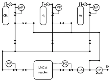
The custom-built gas handling system of the setup can mix up to 3 gases with controllable mass flow ratios, split the gas mixture into two separate gas lines with controllable flow ratios, and deliver them to the optical and X-ray window inlets in the reactor. A gas analyzer monitors the exhaust gas
composition, extracted from the reactor outlet. A membrane rotary pump extracts the outlet gas from the reactor, while a combination of a pressure sensor and variable valve at the exhaust line sets the total pressure of the reactor via a feedback-loop mechanism, see Fig 5. The power of the heater is also set using a feedback loop, using the temperature reading of the thermocouple inside the sample holder. Both the sample heating and gas handling systems are controlled by computer-controlled electronics, developed specifically for this setup.
Figure 5. The gas handling system of LMCat reactor. The abbreviations are MF: mass flow controller, PG: pressure gage controlled variable valve, GA: gas analyzer, RP: rotary pump, EX: exhaust.
hor’s peer reviewed, accepted manuscript. Howe
ver, the online
version of record will be different
from this
version
once it has bee
n copyedited an
d
typeset.
PLEASE CIT
E THIS ARTI
C
LE AS DOI:
10.1063/1.5110656
4. The reactor performance
During its first year of commissioning, the setup has been thoroughly tested and several successful in situ experiments have been performed. Copper foils of 99.99% purity have been molten on the tungsten substrate. Many graphene-growth experiments have been performed while being studied in situ using synchrotron surface X-ray diffraction, Raman spectroscopy, and optical microscopy, at temperatures around 1370 K. Here we present some examples of the obtained results to demonstrate the capabilities of the new instrument.
Fig. 6a shows the in situ optical microscope image of a graphene flake during its growth on the molten copper surface. Figure 6b shows Raman spectra obtained on the same flake. Despite the intense blackbody radiation background at 1370 K, the G band and 2D band of the graphene are visible in the spectra. The signal-to-noise ratio is significantly less than the one obtained at room temperature, however this result confirms that in situ Raman spectroscopy can be employed to monitor 2DMs formation at high temperatures. Figure 6c shows results from in situ synchrotron X-ray scattering obtained on molten copper in our reactor. The results have been obtained by in-plane GIXD scans during experiments at 1D10-ESRF beamline. The recorded intensity is related to the liquid interference function, which is the Fourier transform of the liquid atomic pair correlation function, parallel to and below the liquid surface. Detailed analysis of the obtained in situ data by the optical, Raman, and X-ray techniques will be discussed in separate publications.
Fig 6. Examples of in situ characterization of molten copper and graphene using the newly developed LMCat reactor. (a) in situ optical microscopy of a graphene flake on molten copper at 1370 K, (b) in situ Raman spectroscopy at the indicated point (white cross) in (a), (c) in situ grazing incident X-ray diffraction experiment (in-plane scan) on
molten copper, related to in-plane the atomic correlation length at the surface of the molten phase.
To investigate the copper deposition rate on the windows, we prepared silicon samples cut from highly polished wafers, and fabricated strips of 1 μm x 10 mm of photoresist on them. The Si samples were placed at the optical and X-ray windows where they were exposed to potential copper vapor. We kept the copper molten for 215 minutes, while flowing 10 sccm H2 and 90 sccm Ar (with purity of 6N grade) from the optical window inlet, and keeping the total pressure of the chamber at ~1 bar. The hydrogen was added to avoid unwanted oxidation by the trace of oxygen impurity in the Ar gas. After that, the
hor’s peer reviewed, accepted manuscript. Howe
ver, the online
version of record will be different
from this
version
once it has bee
n copyedited an
d
typeset.
PLEASE CIT
E THIS ARTI
C
LE AS DOI:
10.1063/1.5110656
strips on Si-samples were cleaned by a liftoff process in acetone. The surface was then checked with a profilometer to measure the thickness of deposited copper. The intrinsic roughness of the Si surface and the resolution of the profilometer sets the minimum measurable Cu thickness to ~20 nm, and within this uncertainty we could not detect any measurable copper thickness on the Si samples. By inspecting the optical and X-ray window after more than six months of experiments, we do not see any significant copper deposition on optical or X-ray windows. This overall evidence points towards efficient protection of the windows from the heat and the metal vapor.
5. Conclusions
In this article we described the development of our “LMCat reactor” which is capable of in situ studies of 2D material formation on the surface of liquid metal catalysts, using simultaneously synchrotron X-ray scattering and photon-based techniques such as optical microscopy and Raman spectroscopy. By inducing a specific gas-flow pattern inside the reactor the optical and X-ray windows are protected from the heat and
the deposition of the vapor coming from the molten substrate (the catalyst)
. This setup has proven its capability for in situ investigation of graphene formation on molten copper at 1370 K. The setup can be used for in situ studies on a myriad of other chemical reactions, occurring on molten or solid surfaces at high temperatures and under medium vacuum to atmospheric pressures.6. Supplementary Material
In the supplementary material we show additional information on the copper deposition rate on the reactor inner surfaces and the temperature distribution in the reactor. The simulations have been done under the same conditions as those reported in Fig. 2.
7. Author contribution and acknowledgement:
Virtually every member of the LMCat consortium has contributed to every aspect of the project. But the main contributors for this paper can be listed as following: Inspiration of the LMCat project and establishment of its consortium was mainly realized via M. Saedi in U. Leiden. All the PIs of the consortium supported the process, specially I. Groot in U. Leiden who holds the coordinator responsibility of the project. The protection mechanism of windows for in situ measurements was mainly conceptualized and optimized via M. Saedi using COMSOL simulations. The LMCat reactor and its supporting systems were designed and manufactured via LPM (M. de Voogd, A. Sjardin, and G. van Baarle). The Raman spectrometer was arranged via U. Patras (A. Manikas, C. Galiotis). The
experiments have been carried out and analyzed via a collaboration between CEA (M. Jankowski, G. Renaud), ESRF (F. La Porta, O. Konovalov), U. Patras, and U. Leiden. This project has received funding from the European Union's Horizon 2020 research and innovation programme under grant agreement
hor’s peer reviewed, accepted manuscript. Howe
ver, the online
version of record will be different
from this
version
once it has bee
n copyedited an
d
typeset.
PLEASE CIT
E THIS ARTI
C
LE AS DOI:
10.1063/1.5110656
736299. Responsibility for the information and views set out in this article lies entirely with the authors.