Interim Report of the MIT Sodium Boiling Project
Covering Work through September 30, 1979 Energy Laboratory Report No. MIT-EL-80-005
NOTICE
This report was prepared as an account of work sponsored by the United States Government and two of its subcontractors. Neither the United States nor the United States Department of Energy, nor any of their employees, nor any of their
contractors, subcontractors, or their employees, makes any warranty, express or implied, or
as-sumes any legal liability or responsibility for the accuracy, completeness or usefulness of any information, apparatus, product or process dis-closed, or represents that its use would not infringe privately owned rights.
DEVELOPMENT OF COMPUTER CODE MODELS FOR ANALYSIS OF SUBASSEMBLY VOIDING IN THE LMFBR
Edited by: W. Hinkle Contributing Authors: M. Granziera P. Griffith W. Hinkle M. Kazimi A. Levin M. Manahan A. Schor N. Todreas R. Vilim G. Wilson Energy Laboratory
Department of Mechanical Engineering and
Department of Nuclear Engineering
Massachusetts Institute of Technology Cambridge, Massachusetts 02139
Interim Report of the MIT Sodium Boiling Project
Covering Work Through September 30, 1979
Project Sponsored by U.S. Department of Energy General Electric Co. and
Hanford Engineering Development Laboratory
Energy Laboratory Report No. MIT-EL-80-005 December 1979
Table of Contents Page Title Page . . . . i Table of Contents . . . . . . ii List of Figures . . . . vi List of Tables . . . . . . ix Abstract . . . . . . x I. INTRODUCTION . . . . . . . . . . . . . . . . . . . . I-1 A. Background . . . . . . . . . . . . . . . . . . . I-1 B. Objective and Scope . . . . I-3 References . . . . I-6 II. REVIEW OF ANALYSIS REQUIREMENTS AND AVAILABLE CODES. II-1
A. Introduction . . . . II-1 B. Review of Analysis Requirements . . . . . . . . II-1 1. Ground Rules . . . . . . . . . . . . . . . II-1 2. Results . . . . II-2
a. Rod Bundle Representation . . . . . . II-2 b. Two-Phase Flow Model . . . . . . . . . II-5 c. Heat Transfer Package . . . . . . II-6 d. Numerical Method . . . . . . II-7 C. Review of Available Codes . . . . 11-8
1. Codes Considered . . . . II-8 2. Results . . . . 11-9 D. Comparison of Accident Analysis Requirements and
Codes . . . . 11-9 E. Conclusions and Recommendations . . . . 11-9 1. Code/Model Requirements . . . . . . . . . . 11-9 a. Bundle Representation . . . . 11-9 b. Two Phase Model . . . . II-16 c. Numerical Model . . . . II-16 2. Present Code Capabilities . . . . . . . . . II-16 3. Recommended Code Development . . . . . . . II-16
a. Porous Body/Two Fluid Model . . . . . II-16 b. Porous Body/Mixture Model . . . . . . II-17 References . . . . II-18
III. TWO FLUID CODE DEVELOPMENT . . . . . . . . . . .
A. Introduction . . . . . . . . . . . . . . . .
B. Adaptation of THERMIT. . . . . . . . . . . . 1. Rod Bundle Representation . . . . . . .
a. Radially Variable Equivalent
Diameters . . . . . . . . . . . .
b. Heater and Fuel Rod Models . . . .
c. Representation of Plenum/Blanket Regions . . . . . . . . . . . . .
d. Hex Can Model . . . . . . . . . .
e. Sodium Physical Properties . . . .
2. Numerical Method . . . . . . . . . . .
a. Faster Approach to Steady State . b. Other Ways to Reduce Running Time 3. Input/Output Routines . . . . . . . . .
a. Input Geometry Preprocessor . . .
b. Temperature Field Interpolation . C. Development of NATOF-2D . . . . . . . . . .
D. Development and Implementation of Constituti, Equations and Models . . . . . . . . . . . .
1. Mass Exchange . . . . . . . . . . . . .
2. Momentum Exchange . . . . . . . . . . .
a. Inclusion of r in the Z-Direction Momentum Equation . . . . . . . .
b. Expressions for K, F and F ,v 3. Heat Transfer . . . . . . . . . . . . .
a. Convective Heat Transfer ... b. Radial Heat Conduction in the Liquid
Region . . . . . . . . . . . . . . . .
E. Code Testing and Application . . . . . . . . . .
1. THERMIT Analysis of THORS Test 71H Run 101 2. NATOF-2D Analysis of SLSF-P3A Experiment . F. Summary-Present Status and Plans for FY1980 . .
1. Work Completed During FY1979 . . . . . . .
2. Plans for FY1980 . . . . . . . . . . . . .
Appendix A: THORS Heater Pin Physical Properties and Geometry . . . . . . . . . . . . . Page . . III-1 . . III-1 . . III-2 . . III-2 . . III-2 . . III-2 * . III-3 . . III-3 . . III-4 . . III-5 . . III-5 . . III-6 . . III-6 . . III-6 . . III-7 . . III-9 e . . III-10 . . III-10 . . III-10 . . III-ll . . III-12 . . III-14 . . III-14 III-16 III-22 III-22 III-36 III-41 III-41 III-42 III-45
-- IIIIY II ,,YIIIIIIIIhiIhhIhiYIY h ii IIYYIIIIIIIUiiniin Page Appendix B: Appendix C: Appendix D: Appendix E: Appendix F:
Model for Heat Loss to Surrounding Structure . . . . . . . . . . . . . .
Sodium Physical Property Correlations Old and New Models for the Mass
Exchange Coefficient . . . . . . .
Proposed Correlation for Two Phase Convective Heat Transfer in LMFBR
Rod Bundles . . . . . . . . . . . .
Details of Radial Heat Conduction Model Added to THERMIT . . . . . .
References . . . . . . . . . . . . . . . . . . . .
IV. MIXTURE MODEL CODE DEVELOPMENT . . . . . . . . . .
A. Introduction . . . . . . . . . . . . . . . . .
B. Model Selection . . . . . . . . . . . . . . .
C. Model Formulation and Coding . . . . . . . . .
D. Code Testing and Application . . . . . . . . .
1. Selection of Test Problem . . . . . . . .
2. Results . . . . . . . . . . . . . . . . .
E. Investigation of Numerical Method . . . . . .
F. Summary-Present Status and Plans for FY1980 .
1. Work Completed During FY1979 . . . . . .
2. Plans for FY1980 . . . . . . . . . . . .
References . . . . . . . . . . . . . . . . . . . .
V. DEVELOPMENT OF A MODEL TO PREDICT FLOW OSCILLATIONS IN LOW-FLOW SODIUM BOILING . . . . . . . . . . . .
A. Introduction . . . . . . . . . . . . . . . . . B. Model Formulation . . . . . . . . . . . . . . 1. Hydrodynamic Model . . . . . . . . . . . 2. Thermal Model . . . . . . . . . . . . . . 3. Solution Procedure . . . . . . . . . . . C. Experimental Apparatus . . . . . . . . . . . .
D. Preliminary Analytical Results . . . . . . . .
E. Preliminary Experimental Results . . .... F. Comparison of Sodium and Water Experimental
Results . . . . . . . . . . . . . . . . . . . III-46 III-51 S. III-57 III-66 --- -I---. . . III-72 . III-79 . IV-1 . IV-1 . IV-2 . IV-6 . IV-10 . IV-10 . IV-13 . IV-16 . IV-20 . IV-20 . IV-20 . IV-23 . V-1 . V-1 . V-2 . V-2 . V-5 . V-7 . V-9 . V-13 . V-18 . V-19
Summary-Present Status and Plans for FY1980 . . . V-20 1. Work Completed During FY1979 . . . . . . . V-20 2. Plans for FY1980 . . . . . . V-20 References . . . . V-21 VI. PROGRAM COORDINATION . . . . .. . VI-1
A. Introduction . . . . . . VI-1 B. FY1979 Coordination Activities . . . . . . . . . VI-1 1. Project Meetings and Reports . . . . . . . VI-1
a. Meetings . . . . . . VI-1
b. Reports . . . . . . VI-2 2. Other Activities . . . . . . VI-2
a. Behavior of Sodium (BONA) Working
Group Meetings . . . . . . . . . . . . VI-2 b. Other Meetings . . . . . . . . . . . . VI-3 C. Plans for FY1980 . . . . . . . . . . . . . . . . VI-3
1. Project Meetings and Reports . . . . . . . VI-3 2. Other Activities . . . . . . VI-3
List of Figures
Figure Page
III-1 Comparison of
r
and K for Various Values of III-13a and (T - Ts)e
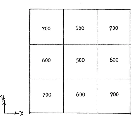
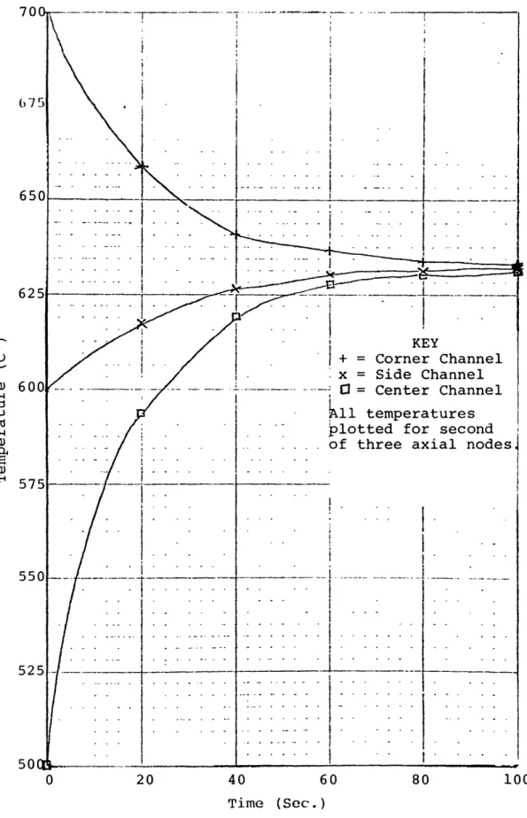
III-2 New Radial Heat Conduction Model - Results of III-18 Four Channel Test Case
III-3 New Radial Heat Conduction Model - Geometry III-20 for Second Test Case
III-4 New Radial Heat Conduction Model - Results of III-21 Second Test Case
III-5 Cross Section View of THORS Bundle 6A Test III-23 Section (ORNL Dwg. 78-6760R)
III-6 Axial Dimensions of THORS Bundle 6A Test III-24 Section (ORNL Dwg. 74-13251)
III-7 Measured Flow Variables from THORS Bundle 6A, III-25 Test 71H, Run 101
III-8 Bottom Boundary Condition: Inlet Velocity to III-27 THORS Bundle 6A, Test 71H, Run 101
III-9 Top Boundary Condition: Outlet Pressure from III-28 THORS Bundle 6A, Test 71H, Run 101
III-10 Temperature Prediction Six Inches Downstream III-29
of Heated Section Outlet for THORS Bundle 6A, Test 71H, Run 101, for Three Different Hex Can Models
III-ll Temperature in the Test Section as a Function III-31 of Axial and Radial Position at 15 Seconds for
THORS Bundle 6A, Test 71H, Run 101
III-12 Comparison of Predicted and Observed Develop- III-32 ment of Saturation Conditions in Test Section,
THORS Bundle 6A, Test 71H, Run 101
III-13 Growth of Void Fraction in Test Section as III-34 Predicted by Single Channel Simulation, THORS
Bundle 6A, Test 71H, Run 101
III-14 Temperature Prediction Six Inches Downstream III-35 of Heat Section Outlet for THORS Bundle 6A,
Test 71H, Run 101
III-15 NATOF-2D Prediction of Temperature at Top of III-38 Heated Zone vs. Time for SLSF-P3A Experiment
Figure Page III-16 NATOF-2D Prediction of Axial Variation of III-39
Coolant Temperature at Various Times for SLSF-P3A Experiment
II1-17 NATOF-2D Void Predictions vs. Time at Three III-40 Different Axial Positions for SLSF-P3A
Experiment
B-la Model for Heat Loss to Surrounding Structure - III-47 True Geometry
B-lb Model for Heat Loss to Surrounding Structure - III-47 Assumed Geometry
D-1 New Model for Mass Exchange Coefficient - III-60 Assumed Geometry for Bubbly Flow
D-2 New Model for Mass Exchange Coefficient - III-62 Assumed Geometry for Annular Flow
D-3 Comparison of Old and New Models for Mass III-65 Exchange Coefficient - Interfacial Area vs.
a for Different Values of P/D
E-1 The Suppression Function, S, in Equation (E-l) III-68 E-2 The Reynolds Number Function, F, in Equation III-71
(E-2)
F-1 New Radial Heat Conduction Model - Nodal III-74 Configuration Used for Derivation of Equations
(F-2) and (F-3)
F-2 New Radial Heat Conduction Model - Nomenclature III-74 Used in Derivation of Effective Conduction Heat
Transfer Coefficient
IV-1 19-Pin Assembly Layout and Calculational Mesh IV-ll Overlay Used for Simulation of French Steady
State Boiling Experiment
IV-2 Predicted Exit Temperature Distribution with IV-14 Liquid Conduction and without Wire Wrap Model,
French Steady State Boiling Experiment
IV-3 Predicted Exit Temperature Distribution without IV-15 Conduction and without Wire Wrap Model, French
Steady State Boiling Experiment
V-1 Schematic of Loop Used in Development of Model V-3
to Predict Flow Oscillations in Low Flow Sodium Boiling
viii
Figure Page
V-2 Schematic of Water Test Loop Used to Simulate V-10
Low Flow Sodium Boiling
V-3 Example of Computer Result for QlIQ2 vs. Time V-15 V-4 Code Prediction of Bubble Pressure vs. Time V-16 V-5 Code Prediction of Total Bubble Length vs. Time V-17
ix
List of Tables
Table Page
II-1 Analysis Requirements - Specific Accidents II-3
II-2 Results - Review of Computer Codes II-10
II-3 Accident Analysis Requirements II-14
II-4 Computer Code Characteristics II-15
III-1 Event Sequence Times as Predicted by NATOF-2D
for SLSF-P3A Experiment III-37
IV-1 Two-Phase Flow Models IV-3
IV-2 Two-Phase Model Comparison IV-5
ABSTRACT
The research program discussed in this report was started in FY1979 under the combined sponsorship of the U.S. Department of Energy (DOE), General Electric (GE) and Hanford Engineering Development Laboratory (HEDL). The objective of the program is to develop multi-dimensional computer codes which can be used for the analysis of subassembly voiding incoherence under pos-tulated accident conditions in the LMFBR. This work is expected to contribute to LMFBR safety analysis in two ways. First, it will provide a capability for obtaining more dependable infor-mation concerning the effects of subassembly voiding incoherence
in LMFBR's of current design. Second, it will provide the cal-culational tools needed to develop new designs with features that could inhibit radial void growth and thus, enhance the reactor safety.
Two codes are being developed in parallel. The first will use a two fluid (6 equation) model which is more difficult to develop but has the potential for providing a code with the ut-most in flexibility and physical consistency for use in the long term. The other will use a "mixture" (< 6 equation) model which is less general but may be more amenable to interpretation and use of experimental data and therefore, easier to develop for use in the near term. To assure that the models developed are not design dependent, geometries and transient conditions typical of both foreign and U.S. designs are being considered.
In addition to the code development, a study is being con-ducted which is aimed at obtaining a basic understanding of flow oscillations observed in low power, low flow sodium boiling ex-periments conducted at ORNL using the THORS test facility. This study includes water tests to simulate low power low flow sodium boiling flow oscillations and development of an analytical model
to predict the oscillations.
During FY1979 an effort has also been made to coordinate this program with other related DOE sponsored programs and activities concerned with sodium boiling R&D. The objectives of this effort are: (1) to assure maximum use is made of data and information available from related programs and (2) to facilitate eventual
acquisition and use of the codes being developed by the appropriate DOE contractors and laboratories.
This report describes work completed on each of the above tasks through September 30, 1979.
I. INTRODUCTION
A. Background
One of the most important safety concerns associated with large commercial sized LMFBR's is the effect of sodium boiling on the consequences of hypothetical accidents. It is well known that void formation within the reactor core would cause a reactivity and power increase, and under cer-tain circumstances, could lead to dryout, overheating of the fuel pins and pin failure. There are indications however, that for specific accidents involving subassemblies and cores of the present designs, there are inherent rate limiting effects that retard the onset of dryout and sustain longer cooling of the fuel. Additional R&D on sodium boiling behavior will greatly help in understanding these effects and may lead to the de-velopment of more favorable designs that can terminate all postulated accidents with limited core damage.
The currently available experimental data concerning sodium voiding under simulated LMFBR accident conditions was obtained from the OPERA, TREAT R Series, THORS and SLSF experiments (Ref. 1). These experiments have included in-pile and out-of-in-pile tests with full length simulated LMFBR subassemblies ranging in size from the 7-pin bundle used in the early OPERA tests to the 19 and 37-pin bundles used in the SLSF P Series tests. Analytical studies by ANL (Ref. 2) have presented convincing arguments, however, that without a specially designed test bundle, a minimum of 61 pins is
I-2
needed to adequately represent the coolant and thermal-hydraulic conditions for a typical LMFBR subassembly. Also, results of
some of the tests completed to date have indicated that two-dimensional boiling incoherence effects are of considerable importance in some accident sequences. (For example, in the case of the Loss of Piping Integrity (LOPI) accident, SLSF P Series test data indicates that such effects would lead to temporary quasi-steady boiling without dryout in the case of an inlet nozzle pipe break of the guillotine type for FFTF.) Therefore, tests with larger bundles are planned. However, computer codes that can be used for analyzing such tests and extrapolating to full size reactor conditions do not presently exist.
The adequacy of a computer code used for LMFBR safety ana-lysis is determined by its ability to predict both the results of separate effects and integral experiments, and to conserva-tively bound the uncertainties which are involved in an extra-polation to a full size reactor system. The end result must be an understanding of the accident progression and the availa-bility of accepted analytical methods which can realistically assess the risk and associated uncertainties. To meet these requirements, the U.S. LMFBR Safety R & D Program has spon-sored development of a number of computer codes, including the integrated system codes MELT (Ref. 3) and SAS (Ref. 4). However, these codes cannot represent the two-dimensional incoherence
effects which may affect sodium boiling progression and limit its rate under some of the test and/or reactor conditions that must be analyzed.
I-3
In the past few years, some attempts (Ref. 5-7) have been made to analyze the effect of incoherent boiling by using mo-dified versions of SAS and COBRA (Ref. 8). However, the one-dimensional channel model used in SAS cannot adequately describe intrasubassembly phenomena. The COBRA code also has some basic limitations, i.e., its treatment of boundary conditions requires the system pressure to be constant and the time dependent inlet flow must be prespecified. Additionally, COBRA has numerical stability problems when used for two phase conditions in the LMFBR assemblies, unless unreal liquid/vapor density ratios are specified.
There have also been attempts to develop new codes. Miao and Theofanous (Ref. 9) have developed a two-dimensional (2D) code, HEV-2D, based on the homogenous equilibrium model for subassembly thermal-hydraulic analyses. Chen et al. (Ref. 10) have extended their single phase forced diversion model (Ref. 11) to include phase change capability. A code based on a slug an-nular flow model, similar to that developed by Chen et. al.
(Ref. 10) was also independently developed by Shih (Ref. 12). All of these codes have fundamental model limitations, however,
and are expected to have a limited range of applicability. Con-sequently, further work on model and code development is needed.
B. Objective and Scope
The objective of the research program discussed in this report is to develop computer code models for multi-dimensional analysis of subassembly voiding under postulated accident con-ditions in the LMFBR. This includes concon-ditions within Line of Assurance 2 (LOA 2) for the Loss of Flow (LOF), Loss of Piping
I-4
Integrity (LOPI), Loss of Shutdown Heat Removal System (LSHRS), and Local Fault (LF) Accidents. It also includes the Transient Overpower (TOP) Accident up the point of fuel dispersal and
fuel coolant interaction.
Two codes are being developed in parallel. The first will use a two fluid (6 equation) model which is more difficult to develop but has the potential for providing a code with the ut-most flexibility and physical consistency for use in the long term. The other will use a "mixture" (< 6 equation) model which is less general but may be more amenable to interpretation and use of available experimental data and therefore, easier to de-velop for use in the near term. To assure that the codes being developed are not design dependent, geometries and transient conditions typical of both foreign and U.S. designs are being considered in the code testing and application.
In addition to the code development, a study is being con-ducted whichis aimed at obtaining a basic understanding of flow oscillations observed in low power, low flow sodium boiling
experiments conducted at ORNL using the THORS test facility
(Ref. 13). This study includes both experimental and analytical work. The experimental work is being done using a water test
loop designed to provide a one-dimensional simulation of the sodium experiments. The analytical work involves development of: (1) a simple analytical model which can predict the oscil-lations observed in the water tests and (2) establishment of a set of criteria for comparison of water to sodium.
During FY1979 an effort has also been made to coordinate this program with other related DOE sponsored programs and activities concerned with sodium boiling R&D. The objectives
--I-5
of this effort are: (1) to assure that maximum use is made of data and information available from related programs and (2) to facilitate eventual acquisition and use of the codes being de-veloped by the appropriate DOE contractors and laboratories.
The following sections of this report describe work com-pleted on each of the above tasks through September 30, 1979.
Section II outlines results of a preliminary study which formed the basis for several decisions concerning the code development. Section III discusses work completed on the two fluid code de-velopment and outlines work planned for FYI980. Section IV provides a similar discussion of the mixture model code deve-lopment. Section V discusses the study of flow oscillations observed in low flow, low power sodium boiling experiments. Section VI outlines completed/planned future efforts to coor-dinate this program with other related DOE sponsored R&D activi-ties.
1- 6
References
1. Hinkle, W.D., Tschamper, P.M., Fontana, M.H., Henry, R.E.
and A. Padilla," LMFBR Safety and Sodium Boiling "Paper Presented at ENS/ANS International Topical Meeting on Nuclear Reactor Safety, October 16:-19, 1978, Brussels, Belgium.
2. Marr, W.W. and M.A. Grolmes; "Effects of Bundle Size on Sodium Boiling in the Simulation of an FTR Pump Coastdown Transient," Trans. Am. Nuc. Soc., 22, 432 (1975).
3. Lewis, C.H., N.P. Wilburn, "MELT III-A: An Improved Neu-tronics, Thermal-Hydraulics Modeling Code for Fast Reactor Safety Analysis," HEDL-TME-76-73, December 1976.
4. Stevenson, M.G., Bohl, W.R., Dunn, F.E., Heames, T.J., Hoppner, G. and L.L. Smith, "Current Status and Experi-mental Basis of the SAS LMFBR Accident Analysis Code," Proc. ANS Conf. Fast Reactor Safety, USAEC
CONF-740401-03, Beverly Hills, California, 1974.
5. Dunn, F.E. "SAS3D Prediction of Intrasubassembly Boiling Incoherence," Trans. Am. Nucl. Soc., 28, 431 (1978). 6. Marr, W.W. and J.T. Hwang, "An Approach for Treating
Two-Dimensional Coolant Boiling in the LMFBR Fuel Sub-assembly," Trans. Am. Nucl. Soc., 27, 459 (1977).
7. "Advanced Safety Analysis," GEFR-14038-14, Fourteenth Quarterly Report, General Electric Company, March 1978. 8. Rowe, D.S., "A Mathematical Model for Transient Subchannel
Analysis of Rod-Bundle Nuclear Fuel Elements," J. of Heat Transfer, Trans. ASME, Series C, Vol. 95, No. 2, 211, May
1973.
9. Miao, C. and T.G. Theofanous, "A Numerical Simulation of
the Two-Dimensional Boiling (Voiding) in LMFBR Subassemblies," Int. Fast Reactor Safety Conf., Chicago, Ill., October 1976.
10. "Reactor Development Program Progress Report," ANL-RDP-73, July 1978.
11. Chen, W.L. et.al., "A Simple Forced Diversion Model for Study of Thermal-Hydraulic Transients in an LMFBR Sub-assembly," Nucl. Eng. Design, 45, 53 (1978).
12. Shih, T.A., "The SOBOIL Program: A Transient, Multichannel, Two-phase Flow Model for Analysis of Sodium Boiling in LMFBR Fuel Assemblies,"Technical Note ST-TN-79008, General Electric Co., Advanced Reactor Systems Dept., March 1979.
13. Ribando, R.J., et. al., "Sodium Boiling in a Full Length 19-Pin Simulated Fuel Assembly (THORS Bundle 6A)," ORNL/TM-6553, Oak Ridge National Laboratory, January 1979.
II. REVIEW OF ANALYSIS REQUIREMENTS AND AVAILABLE CODES
A. Introduction
Before starting work on the code development, a preliminary study was conducted for the purpose of answering several ques-tions concerning the project scope and approach. These quesques-tions were as follows:
1) What are the code/model requirements for analysis of
sodium boiling and voiding incoherence under postulated LMFBR accident conditions?
2) To what extent do previously available codes fail to meet these requirements?
3) What is the recommended scope and approach for addi-tional code/model development?
4) Can any of the previously available codes provide a starting point for this work?
B. Review of Analysis Requirements
1. Ground Rules
Before the first of the above questions could be answered, it was necessary to identify the range of LMFBR accident con-ditions and geometries to be considered. In order to do this
the following set of ground rules was decided upon.
a. Consider Loss of Flow (LOF), Loss of Piping Integrity (LOPI), Loss of Shutdown Heat Removal System (LSHRS), Local Fault (LF) and Transient Overpower (TOP) Acci-dents.
b. Consider both the initiating phase and long term cooling for the LOF, LOPI, LSHRS and LF accidents. Assume no cladding or fuel melting during initiating
phase. Allow for possibility of some fuel melting and cladding failure by the time long term cooling phase is reached.
II-2
C. Consider TOP accident only up to the point of cladding
failure.
d. Consider single bundle, not whole core or loop. Code(s) should, however, be able to connect appropriately to full core or loop codes.
e. Consider both U.S. and foreign geometries. 2. Results
With these ground rules in mind, each accident was considered and the analysis requirements identified. These requirements were organized into four categories: bundle representation, two phase flow model, heat transfer package and numerical method. The re-sults for each accident are summarized in Table II-1. Overall conclusions are outlined below.*
a. Bundle Representation
1) A 2 or 3D analysis is needed for all of the
accidents for which local incoherence effects might be important. This includes the LOF, LOPI, TOP and LF accidents.
2) Either the porous body or subchannel approach could be used to represent an LMFBR subassembly. A porous body approach is probably preferable, however, for the following reasons
a) The amount of detail in the rod bundle representation can be more easily varied than with the subchannel model. Thus, it is easier to adjust the detail to match the accident conditions being ana-lyzed and minimize computation costs.
*These conclusions reflect the collective judgement of the MIT project group. They were arrived at after review of available background information (Ref. Section I) and several meetings and discussions.
Bundle
Accident BneTwo-Phase Flow Model
Representation
LOF > 1D Bubbly Flow
Subchannel orSubchannel MlilgFo
Multislug Flow Fixed Regime Model?
or
Porous Body Concurrent Annular Flow Mixture Model (HEM with
Flow Oscillations slip or Drift Flux)*
Inlet Flow Reversal Two-Fluid Model
Bidirectional Concurrent
Annular Flow *except for bidirectional
Re-entry flow
Low Flow & Natural Circulation
LOPI > lD Same - except flow oscillations
Subchannel and low flow/natural circulation H
or conditions may be more imnortant Same as for LOF Porous Body to CHF calculation
j
LSHRS 1D l1 Natural Convection Flow
2 Natural Convection Flow Subchannel Bubbly Flow
or Bidirectional Cocurreit Same as for LOF
Porous Body Annular Flow Flow Oscillations
Bulk Flow - Subcooled
LF > ID Localized Voiding in Wake of Mixture Model
Subchannel Blockage
or Recirculating Flow in Vicinity of Two-Fluid Model Porous Body Blockage
> lD
Subchannel
or
Porous Body
Single Phase Flow Two-Phase Flow
,7 Same as for LOF TOP
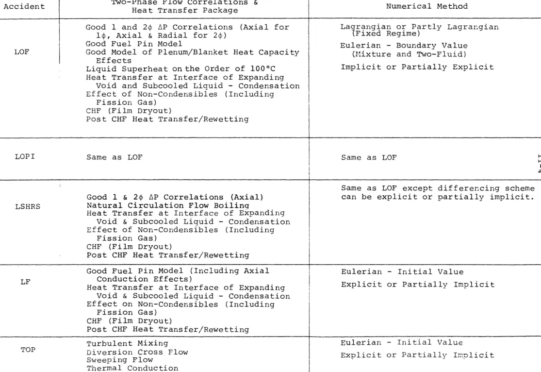
Table II-1
Analysis Requirements - Specific Accidents (continued)
Accident Two-Phase Flow Correlations & Numerical Method
Accident HaTrnfrPcgeNumerical Method
Heat Transfer Package
Good 1 and 2p AP Correlations (Axial for Lagrangian or Partly Lagrangian
1 , Axial & Radial for 2 ) (Fixed Regime)
Good Fuel Pin Model Eulerian - Boundary Value
LOF Good Model of Plenum/Blanket Heat Capacity (Mixture and Two-Fluid) Effects
Liquid Superheat on the Order of 1000C Implicit or Partially Explicit Heat Transfer at Interface of Expanding
Void and Subcooled Liquid - Condensation Effect of Non-Condensibles (Including
Fission Gas) CHF (Film Dryout)
Post CHF Heat Transfer/Rewetting
LOPI Same as LOF Same as LOF H
Same as LOF except differencing scheme Good 1 & 24 AP Correlations (Axial) can be explicit or partially implicit. LSHRS Natural Circulation Flow Boiling
Heat Transfer at Interface of Expanding Void & Subcooled Liquid - Condensation Effect of Non-Condensibles (Including
Fission Gas) CHF (Film Dryout)
Post CHF Heat Transfer/Rewetting
Good Fuel Pin Model (Including Axial Eulerian - Initial Value
LF Conduction Effects)
Heat Transfer at Interface of Expanding Explicit or Partially Implicit
Void & Subcooled Liquid - Condensation Effect on Non-Condensibles (Including
Fission Gas) CHF (Film Dryout)
Post CHF Heat Transfer/Rewetting
TOP Turbulent MixingDiversion Cross Flow
Sweeping Flow
Thermal Conduction
Eulerian - Initial Value
II-5
b) This model provides a treatment of trans-verse momentum effects which is more exact than the one used in the subchannel model. c) The amount of detail can be such as to
make the model essentially equivalent to one which represents every subchannel
--if necessary.
3) RZ or RZO geometry would be easier to use for2D or 3D porous body code -- because of the hexa-gonal fuel pin arrangement in LMFBR assemblies; but XYZ geometry could also be used.
b. Two-Phase Flow Model
1) A wide range of flow regimes could occur for
the accidents considered. These include bubbly, multislug, and cocurrent or bidirectional
an-nular. The only model which has sufficient flexibility to represent all of these regimes is the two fluid model. A mixture model could be used for all regimes except bidirectional annular. The fixed regime model can be used if the analysis is to focus on conditions asso-ciated with one regime. (For example, the
multislug or concurrent annular model could be used to represent LOF conditions just prior to the onset of flow reversal.)
2) Sodium has a large liquid to vapor density ratio and tends to superheat [Ref. Item C.3) below]. This can result in larger local values of dp/dx and dp/dt leading to non-equilibrium conditions and oscillatory flow.
3) Two-phase AP (axial and radial) would be impor-tant to determining the shape of an expanding two-phase region ("bubble"). Thus a good model and supporting data are needed.
II-6
4) Low flow and natural circulation conditions (both low and high quality) are important for the LSHRS accident and the tail end of the initiating phase of the LOF and LOPI accidents.
5) Analysis of void progression should include consideration of the effect of non-condensibles
(including fission gas) on void progression. c. Heat Transfer Package
1) Fuel pin stored energy release vs. time is
important for the LOF and LOPI accidents. Axial conduction could be important to the LF accident. Also, effect of the heat capa-city of the fuel assembly structure in the fission gas plenum and blanket regions would be important for the LOPI and (to a lesser extent) LOF accidents. The fuel pin model should therefore include such effects.
2) Radial heat conduction in the liquid region could be important for low flow conditions because of the high thermal conductivity of sodium. (Heat conduction to the hex can could also be important for analyzing small rod bun-dle experiments. Ref. the SLSF P3 and THORS
Bundle 6 experiments, for example.)
3) Sodium superheat is expected to be less than 800C in reactor configurations, but supporting
evidence based on reactor operational experi-ments is not yet available. Locally, superheat greater than 100 0C may be possible. In small
test facilities superheat greater than 1000C
has been observed. Therefore, until such time the superheat mechanism is better understood, new analytical models and codes should be
II-7
able to represent superheat on the order of
1000C.*
4) The heat transfer mechanism at the interface between the expanding void and subcooled li-quid regions would be important in determining void progression. Mixing and condensation at this interface would be affected by flow
oscillations.
5) The condensation heat transfer model must be able to account for presence of non-condensible gases (including fission gas released from
failed fuel pins).
6) CHF probably occurs under cocurrent, counter-current or stagnated annular flow conditions and results from depletion of the annular film. Evaporation, entrainment, interfacial shear and flow oscillation effects all need to be consi-dered in any dryout model. (However, develop-ment of a CHF model is considered to be low
priority compared to development of a capability for analyzing boiling progression up to CHF.) 7) The heat transfer package should include
capa-bility for calculating the entire boiling curve. Post CHF heat transfer may be significant for sodium because of its high surface tension (good wetability) and high thermal conductivity.
d. Numerical Method
1) If a fixed regime model is used, the code would
have to be based on a Lagrangian or partially Lagrangian approach.
2) For either the two fluid or mixture model, the code should be based on an Eulerian/boundary
*This conclusion is based on information and recommendations provided by P.W. Garrison of the Oak Ridge National Laboratory.
II-8
value approach in order to be able to represent the range of boundary conditions associated with the various accidents (except possibly
for the LF accident).
3) The best differencing scheme (with respect to achieving a balance between avoiding numerical instability and increasing computation diffi-culty) approaches would be the following:
a) LOF/LOPI accidents- implicit or partially explicit
b) LSHRS/LF accidents -explicit or partially implicit
C. Review of Available Codes 1. Codes Considered
Next a survey was made to determine the characteristics of available computer codes that might be used as a starting point for this project. The following codes were considered (Refs. 1-22):
BACCHUS BLOW-3 COBRA-IIIC COBRA-IIIP COBRA-IV COBRA-3M COBRA-DF COBRA-TF COMMIX FLICA-III FLINA FLINT HEV-2D NATREX NATOF-lD NATOF-2D SABRE SAS SOBOIL THERMIT TRAC WOSUB
2. Results
The results of this survey are shown in Table II-2. This table provides information concerning: bundle representation, two phase flow model, two phase flow correlations/heat transfer package, and numerical method.
D. Comparison of Accident Analysis Requirements and Codes
In order to answer the second, third, and fourth questions listed in Section II.A, a comparison was made of the accident analysis requirements and available codes. For a first cut, this comparison was made by choosing only a few of the more important requirements/code characteristics as a basis for comparison. These were the following:
a. Bundle Representation Dimension (1, >lD)
Fuel/Clad Representation (Subchannel, Porous Body) b. Two Phase Flow Model
Fixed Regime (Slug Flow) Mixture (HEM, Drift Flux) Two-Fluid
c. Numerical Method
Eulerian (Boundary Value, Initial Value) Lagrangian or Partly Lagrangian
[No evaluation was made of the two-phase flow correlations and heat transfer package vs. analysis requirements.]
The results of this comparison are provided in Tables II-3 and II-4.
E. Conclusions and Recommendations
1. Code/Model Requirements
a. Bundle Representation
1) Dimension - 1,2 and 3D, depending on the accident
to be analyzed. A 3D code is needed to analyze effects of local voiding incoherences for
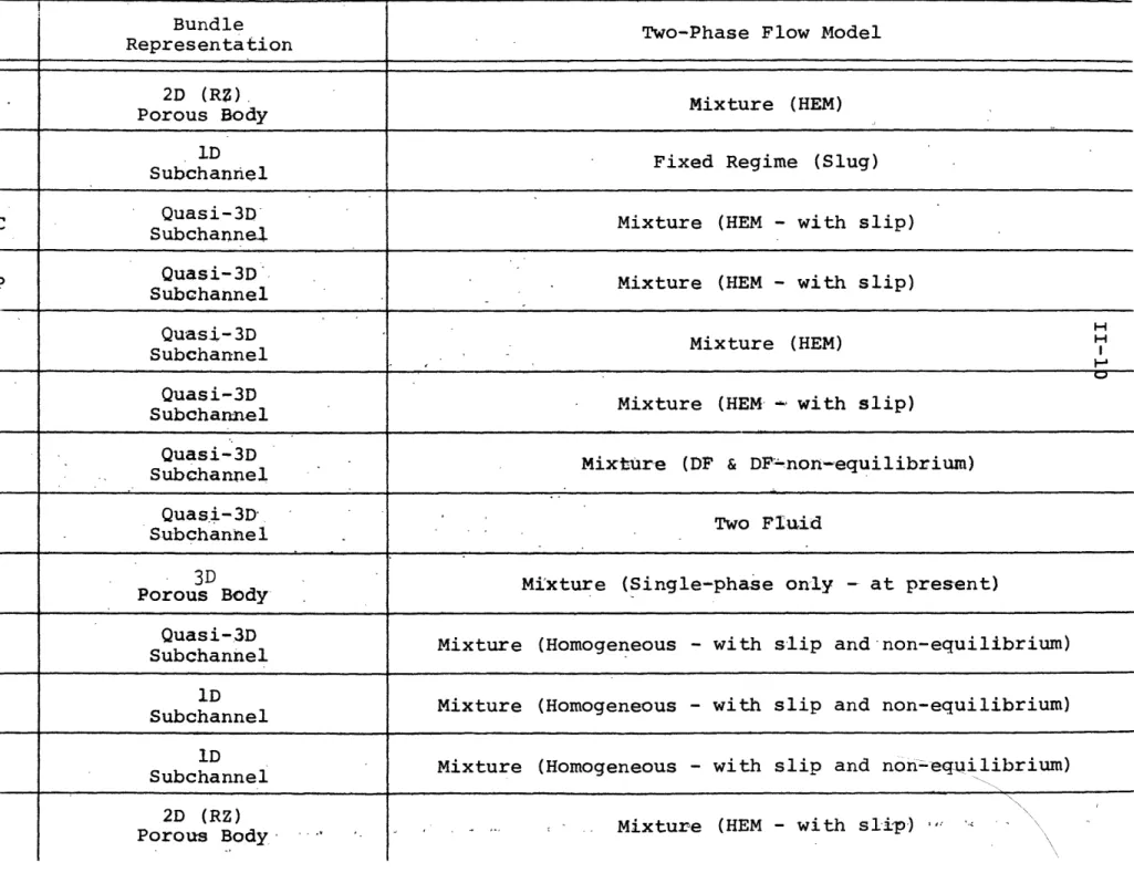
postu-Table
II-2-Results - Review of Computer Codes
Code Bundle Two-Phase Flow Model
Representation
BACCHUS 2D (RZ)Mixture (HEM)
Porous Body
BLOW-3 1D Fixed Regime (Slug)
Subchannel
COBRA-IIIC Quasi-3D Mixture (HEM - with slip)
Subchannel
COBRA-IIIP Quasi-3D Mixture (HEM- with slip)
Subchannel
COBRA-IV Quasi-3D Mixture (HEM) H
Subchannel
COBRA-3M Quasi-3D Mixture (HEM- with slip)
Subchannel
COBRA DF Quasi-3D Mixture (DF & DF'-non-equilibrium)
Subchannel
COBRA-TF Quasi-3D Two Fluid
Subchannel
COMMIX 3D Mixture (Single-phase only -at present)
ICAIX Porous Body
FLICA III Quasi-3D Mixture (Homogeneous - with slip and non-equilibrium)
Subchannel
FLINA D Mixture (Homogeneous - with slip and non-equilibrium)
Subchannel
FD
FLINT S DnMixture (Homogeneous - with slip and non-equlilibrium)
Subchannel
Mixture (HEM - with slip)
-2D (RZ)
Porous Body HEV-2D
(continued) Two-Phase Flow Correlations &
Heat Transfer Package Numerical Method
BACCHUS LMFBR Eulerian - Initial Value? Implicit?
BLOW-3 LMFBR
COBRA-IIIC LWR Eulerian - Initial Value (Iterative)
Partially Implicit
COBRA-IIIP LWR Eulerian - Initial Value (Iterative)
LMFBR (single phase bnly) Partially Implicit
COBRA-IV LWR Eulerian - Boundary Value
Explicit
COBRA-3M LMFBR Eulerian - Boundary Value
Partially Implicit
COBRA DF LWR Eulerian - Boundary Value
Partially Implicit
COBRA-TF LWR Eulerian - Boundary Value
Partially Implicit
COMMIX LMFBR (No HT Package) Eulerian - Boundary Value
Implicit?
FLICA III LMFBR Eulerian - Initial Value 'iterative)
L RImplicit?
FLINA LMFBR
FLINT LMFBR Eulerian - Initial Value
FLINT LMFBR Implicit
HEWImpliciB
Eulerian - Boundary Value
Partially Implicit Code
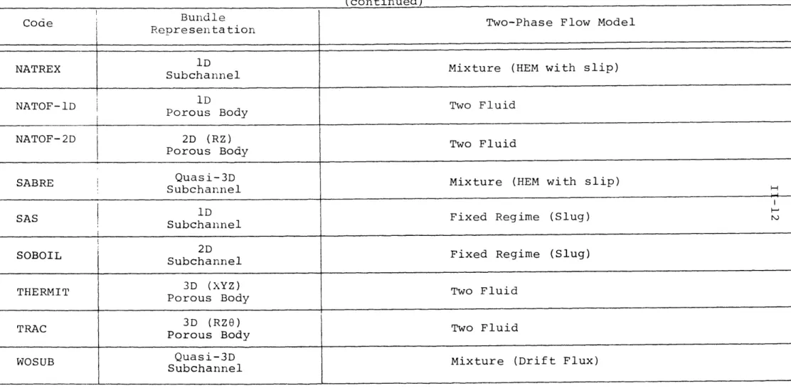
Table II-2
Results - Review of Computer Codes (continued)
Code Bundle Two-Phase Flow Model
CdRepresentation
NATREX lD Mixture (HEM with slip)
Subchannel
NATOF-D iD Two Fluid
NATOF-D Porous Body
NATOF-2D 2D (RZ) Two Fluid
Porous Body
SABRE Quasi-3D Mixture (HEM with slip)
Subchannel
SASID Fixed Regime (Slug)
Subchannel
SOBOIL 2D Fixed Regime (Slug)
Subchannel
3D (XYZ)
THERMIT3D THERMIT Porous Body(XYZ) Two Fluid
TRAC3D (RZO) Two Fluid
Porous Body
WOSUB Quasi-3D Mixture (Drift Flux)
(continued)
Two-Phase Flow Correlations & Numerical Method
Heat Transfer Package
Eulerian
NATREX LMFBR
Eulerian - Boundary Value
NATOF-iD LMFBR Partially Implicit
Eulerian - Boundary Value
NATOF-2D LMFBR Partially Implicit
H
SABRE LMFBR
Eulerian - Initial Value (Before Boiling)
SAS LMFBR Lagrangian or Partially Lagrangian (After Onset of
Boiling)
Eulerian - Initial Value (Liquid)
SOBOIL LMFBR Langrangian (Vapor Bubbles)
Eulerian - Boundary Value
Partially Implicit
Eulerian - Boundary Value
TPartially Implicit
Eulerian - Initial Value
WOSUB LWR
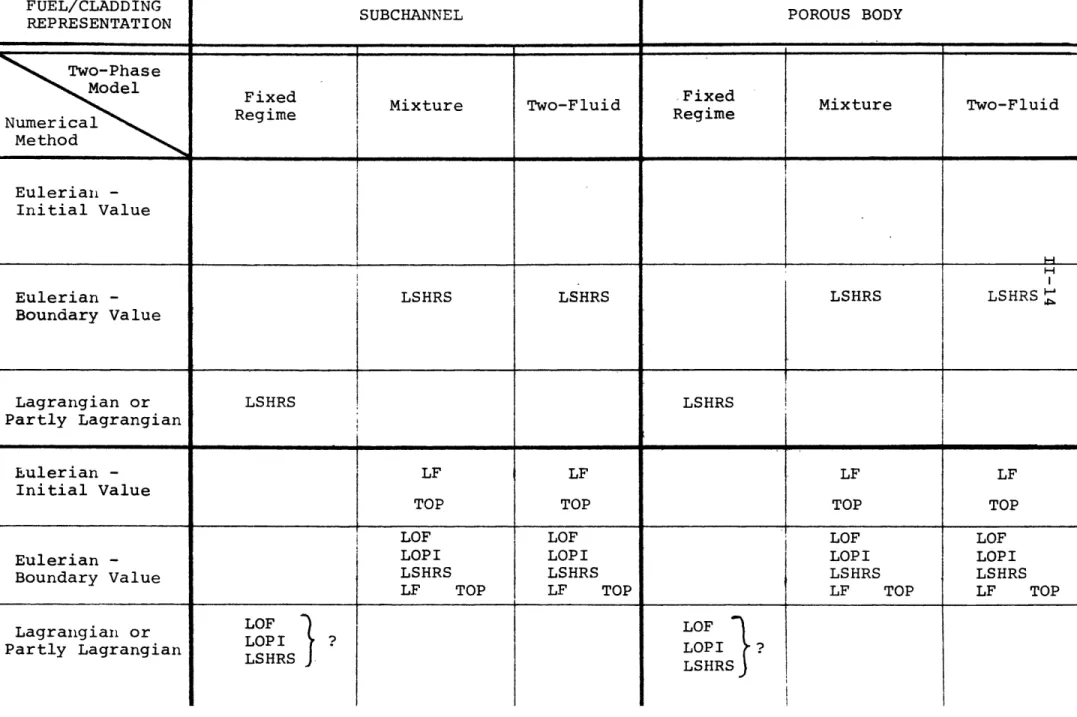
Table II-3
Accident Analysis Requirements
FUEL/CLADDING SUBCHANNEL POROUS BODY
REPRESENTATION
0
Two-Phase
Model Fixed Rime
SFixed Mixture Two-Fluid Fixed Mixture Two-Fluid
Regime Regime QNumerical Method Eulerian -Initial Value H Eulerian - LSHRS LSHRS LSHRS LSHRS Boundary Value I Lagrangian or LSHRS LSHRS Partly Lagrangian Eulerian -Initial Value LF TOP LF TOP LF TOP TOP
LOF LOF LOF LOF
Eulerian - LOPI LOPI LOPI LOPI
Boundary Value LSHRS LSHRS LSHRS LSHRS
LF TOP LF TOP LF TOP LF TOP
Lagrangian or Partly Lagrangian LOF LOP I LSHRS LOF LOPI ? LSHRS _ _~
FUEL/CL.ADDING ,
Z REPRESENTATION SUBCHANNEL POROUS BODY
O
H
U)
z Two-Phase
Todel Fixed Regime Mixture Two-Fluid Fixed Regime Mixture Two-Fluid C Numerical
Method .. _ ___
Eulerian - FLINA?
Initial Value FLINT
S Eulerian - NATREX? NATOF- 1D
q Boundary Value
H
Lagrangian or BLOW-3?
Partly Lagrangian SAS
Eulerian -Initial Value COBRA-IIIC COBRA-IIIP FLICA-III WOSUB BACCHUS?
Eulerian - COBRA-IV COMMIX INATOF-2D (RZ)
Boundary Value I COBRA-3M COBRA-DF !
COBRA-TF HEV-2D (R,Z) TRAC (RZG)
SABRE? THERMIT(XYZ)
SABRE?
Lagrangian or Partly Lagrangian
II-16
lated accidents in which both radial and azimuthal variations are important. Such accidents could include: (1) Local Fault Accidents and (2) Loss of Flow or Loss of Piping Integrity Accidents which occur under conditions involving severe azimuthal varia-tions in local geometry.
2) Fuel/Clad Representation - Either the sub-channel or porous body could be used. The subchannel model provides a more detailed representation of fuel-coolant geometry. It would have disadvantages, however, with respect. to running time required for a com-plete representation of an LMFBR assembly. Also, it only treats transverse momentum effects in an approximate manner.
b. Two Phase Model
Either two fluid or mixture model could be used. The two-fluid model would be more general and take somewhat longer to develop. The mixture model would be simpler and take less time to develop -- and may have advantages with respect to interpretation and use of available experi-mental data.
c. Numerical Method
The Eulerian/boundary value approach and implicit or partially implicit differencing scheme.
2. Present Code Capabilities
At present there is no single code with the characteris-tics listed in E.l. (Ref. Table II-4).
3. Recommended Code Development a. Porous Body/Two Fluid Model
Adapt XYZ LWR code THERMIT to sodium and LMFBR conditions. Continue parallel development of RZ code, NATOF-2D.
II-17
b. Porous Body/Mixture Model
Develop three or four equation model/code based on THERMIT.
[The two-fluid code, THERMIT was recommended as a basis so that the theoretical and numeri-cal differences between the mixture model and two fluid codes will be clearly understood when making comparisons. Also, this approach will make it possible to take advantage of an existing code structure and numerical method which repre-sents the present state-of-the-art. The reasons
for choosing THERMIT, rather than other state-of-the-art codes such as TRACorCOMMIX were the following: (1) TRAC was written before THERMIT and therefore there were some improvements in THERMIT. Also, TRAC includes representation of an external loop and is therefore structured differently and much larger than THERMIT (which is designed specifically for core calculations).
(2) Only a single-phase version of COMMIX was available, and the two-phase, two-fluid version was not expected to be available until mid-1979.]
II-18 References
1. "French Studies on Sodium Boiling Applied to Fast Neutron
Reactor Safety, State of the Art," Commisariat A L'Energie Atomique Report, Grenoble, August 1978.
2. Bottoni, M., Peppler, W., and D. Strueve,"Theortical In-terpretation of Sodium Boiling Experiments in a 7-pin Bundle Under Flow Rundown Conditions with the Computer
Code BLOW-3A," Institut fur Reactorentwicklung Gesellschaft fur Kernforschung, Karlsruhe, Undated technical paper ob-tained from N. Todreas, MIT, 1978.
3. Bowring, R.W. and P. Moreno, "COBRA-IIIC/MIT Computer Code Manual," MIT Dept. of Nuclear Engineering, Draft EPRI Report, March 1976.
4. Masterson, R. and L. Wolf, "COBRA-IIIP: An Improved Version of COBRA for Full-Core Light Water Reactor Analysis," Nuclear Engineering and Design, Vol. 48, pp. 293-310, August 1978. 5. Stewart, C.W., et.al., "COBRA-IV: The Model and the Method,"
BNWL-2214, Pacific Northwest Laboratories, March 1976. 6-8. Unpublished information obtained from Battelle Northwest
Laboratories, 1978.
9. Sha, W.T., et.al., "COMMIX-l: A Three-Dimensional Transient Single-Phase Component Computer Program for Thermal Hydraulic Analysis," ANL-77-96 (NUREG-0415), January 1978.
10. Menant, B., "Permanent Boiling in Rod Bundles: Calculations with the FLICA-IIB Code," Paper Presented at Sixth Meeting of Liquid Metal Boiling Working Group, Risley, UK, October
1-3, 1975.
11. Costa, J., et.al.', "Ebullition Du Sodium en Regime Transitoire Redistribution De Debit: Experiences et Calculs," Paper
Pre-sented at International Conference on Engineering of Fast Reac-tor for Safe and Reliable Operation, Karlsruhe, October 9-13,
1972.
12. Grand, D. and A. Latrobe, "FLINT: A Code for Slow Flow Tran-sients in a Single Channel," Paper Presented at Seventh
Meeting of Liquid Metal Boiling Working Group, Petten, Holland, June 1-3, 1977.
13. Miao, C. and T. Theofanous, "A Numerical Simulation of the Two Dimensional Boiling (Voiding) in LMFBR Subassemblies," Paper Presented at International Meeting on Fast Reactor
Safety and Related Physics, Chicago, ILL., October 5-8, 1976. 14. Latrobe, A., "A Comparison of Some Implicit Finite Difference
Schemes Used in Flow Boiling Analysis," undated technical paper obtained from N. Todreas, MIT, 1978.
II-19
15. Autruffe, M., "Theoretical Study of Thermohydraulic Phenomena for LMFBR Accident Analysis," M.S. Thesis,
Department of Mechanical Engineering, MIT, September 1978. 16. Granziera, M.R. and M.S. Kazimi, "NATOF-2D: A Two
Dimen-sional Two-Fluid Model for Sodium Flow Transient Analysis," Trans. ANS, 33, 515, November 1979.
17. Gosman, A.D., et.al., "The SABRE Code for Prediction of Coolant Flows and Temperaturs in Pin Bundle Containing Blockages," AEEW-R905, 1973.
18. Stevenson, M.G., Bohl, W.R., Dunn, F.E., Heames, T.J.,* Hoppner, G. and L.L. Smith, "Current Status and Experi-mental Basis of the SAS LMFBR Accident Analysis Code, " Proc. ANS Conf. Fast Reactor Safety, USAEC
CONF-740401-03, Beverly Hills, California, 1974.
19. Shih, T.A., "The SOBOIL Program: A Transient, Multichannel, Two-phase Flow Model for Analysis of Sodium Boiling in LMFBR Fuel Assemblies," Technical Note ST-TN-79008, General Electric Co., Advanced Reactor Systems Dept., March 1979.
20. Reed, W.H. and H.B. Stewart, "THERMIT: A Computer Program for Three-Dimensional Thermal-Hydraulic Analysis of Light Water Reactor Cores," Mid-1978 draft of forthcoming EPRI report.
21. "TRAC-Pl: An Advanced Best Estimate Computer Program for PWR LOCA Analysis," Las Alamos Scientific Laboratory, LA-7279-MS, Vol. I, June 1978.
22. Wolf, L, Faya, A., Levin, A., and L. Guillebaud, "WOSUB -A Subchannel Code for Steady-State Reactor Fuel Pin Bundles Vol. I, Model Description, MIT-EL-78-023, September 1978.
III. TWO FLUID CODE DEVELOPMENT
A. Introduction
The objective of this task is to develop a calculational tool based on the two fluid model which can be used for ana-lysis of sodium boiling. The two fluid model uses separate partial differential equations to express conservation of mass, momentum and energy for each individual fluid phase. Such a formalism allows very general and physically reasonable model-ling of relative motion of the phases and thermal disequilibrium; but, this in turn requires mathematical expressions for the
exchange of mass, momentum and energy. Accordingly, an impor-tant part of the work associated with this task is directed towarded obtaining such expressions.
On the basis of the recommendation of Section II, it was decided that work on this task would follow two approaches. The first is to adapt the LWR XYZ code, THERMIT (Ref. 1) to
sodium and LMFBR conditions. The second is to continue work which was started in FY1978 on development of an LMFBR RZ code, NATOF-2D. Both of these codes use a two-fluid, porous body
representation and a semi-implicit method for the numerical solution of the fluid dynamics equations. Therefore, much of the work being carried out under this task is common to both. The work which has been completed during FY1979 is described
in Sections III.B through III.E* which follow. A summary and outline of work planned for FY1980 is given in Section III.F.
*Note that all subtasks in Section III.B and some in Section III.D are also applicable to development of a mixture model code based on THERMIT (See Section IV).
III-2
B. Adaptation of THERMIT
1. Rod Bundle Representatives
a. Radially Variable Equivalent Diameters THERMIT is written in rectangular coordinates. In order to use the code to analyze LWR square array rod
bundles (as was originally intended) only one axial hydraulic diameter was required as user input. In the case of LMFBR hexagonal arrays, however, this is not the case. Accordingly, the code has been modified so as to accept radially variable, axial heated and wetted equivalent diameter for use in the heat transfer and friction calculations respectively.
b. Heater and Fuel Rod Models
The LWR version of THERMIT contains a UO2 - Zircaloy fuel rod model. This model has been deleted and replaced by a boron nitride (BN) heater model with constant material
properties similar to those used in the THORS experiments. The properties and details of rod geometry used are based
on Ref. 2 and given in Appendix A. Since the code calculations are based on three zone geometry, the inner BN and heater
ribbons were volume weight smeared as follows:
pc
dv
R
1
p cdv p 1 (R2 + (pc 2 R2 (I-) pc = 3.275 x 10⁶ (J/m3 OK) Sfk dv k + k 2 1 R 1 (III-2)dv
2
R2
k = 39.39 w/m oKIII-3
Work is presently underway to incorporate a new fuel rod model. Initially, a model similar to the previous
UO2 - Zircaloy model will be used. The only difference will
be that the new model will use material properties and gap conductivity correlations appropriate for LMFBR (UO2/PuO2 -Stainless Steel) fuel rods. Later, consideration will be given to incorporating a more detailed model such as used in COBRA-3M or SIEX.
c. Representation of Plenum/Blanket Regions
Work is presently underway to modify THERMIT to allow for axially varying fuel rod properties. This capability is necessary to be able to represent plenum/blanket regions of fuel assemblies. In the LWR version of THERMIT the fuel rod materials are assumed to extend for the full axial height of the system. Thus the thermal inertia of the fission gas plenum cannot be adequately modeled.
In the new version of THERMIT the user will be able to model a fuel rod by specifying the number of axial zones and the material in each zone. As many zones as desired may be specified, limited only by the number of axial meshes. This will allow the user considerable flexibility in modeling physical systems.
d. Hex Can Model
In the LWR version of THERMIT an adiabatic boundary con-dition around the radial perimeter of the region was required,
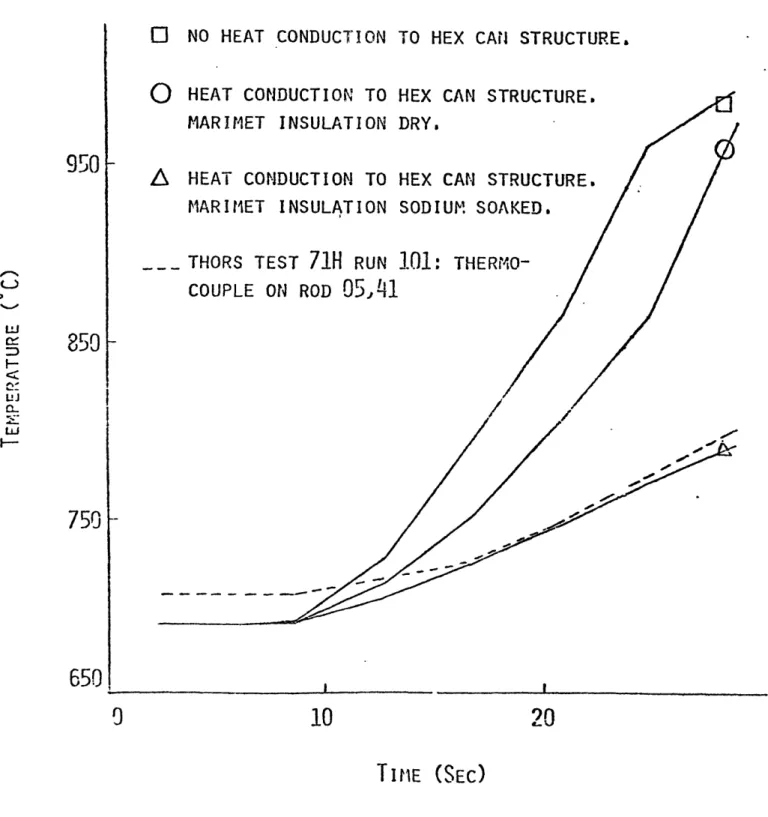
The new version of THERMIT, however, provides the option of including heat loss to the surrounding structure. This capa-bility was added as a result of attempts to model the THORS
Bundle 6A experiments (see Section III.E.1). it was found that THERMIT couldn't adequately predict boiling inception, because there was no provision for modeling the heat losses to the hex can and surrounding insulation.
A multi-layer conduction model is used to represent the heat loss to the structure (see Appendix B for details). Heat flow in the radial direction only is conducted and azi-muthal symmetry is assumed. Because of the large decrease in the sodium thermal conductivity at the onset of boiling, the heat loss from any fluid channel that has a void fraction greater than zero is neglected. If desired, the heat loss calculations can be bypassed entirely, simulating an adia-batic boundary condition.
It was found (Section III.E.1) that the inclusion of heat loss to the hex can and surrounding structure had a
significant effect upon the prediction of boiling inception in the THORS experiment. It is expected that any attempt to model a transient for a geometry as small as a single fuel assembly will need to consider the thermal inertia of the surrounding structure, because the heat losses can be signi-ficant.
e. Sodium Physical Properties
Fluid property correlations for water have been replaced by correlations for sodium. The sodium correlations were taken from Refs. 3 and 4. The correlations in Ref. 3 are based on more complete data than the correlations in Ref. 4. Correlations for liquid enthalpy, vapor conductivity, vapor viscosity, and liquid surface tension were not available
III-5
in Ref. 3, however, and were therefore taken from Ref. 4. Appendix C contains a summary of the correlations used. 2. Numerical Method
a. Faster Approach to Steady State
THERMIT has a semi-implicit solution method (i.e., the
maximum time step is limited by the Courant velocity condition), and steady state solutions are found by starting from an
initial guess and then running an unperturbed transient until an equilibrium solution is achieved. This equilibrium
solution is the steady state solution from which a true transient may be started via the restart capability in the code. Initial application of the code to a representative test case indicated that the CPU time required in order to achieve a steady state solution was excessive. An
investigation was therefore initiated to find a remedy to this problem.
As a result of this investigation, the decision was made to: (1) convert the code to double precision and
(2) provide an option to suppress transverse flow during approach to steady state. The second modification allows the user to run with the transverse flow suppressed, and then to restart with the transverse flow and run a few seconds of real time to adjust the transverse flow. The effect
of these modifications was found to be the following: Modification ' % Decrease in CPU Time
Double precision 7
b. Other Ways to Reduce Running Time
An effort will be made to identify and implement additional code modifications which significantly reduce running time. One possibility currently under consideration is to provide a means for automatic variation of the
spatial mesh during a transient boiling calculation. Such a modification would enable the user to specify a fine mesh only for those parts of the transient where it is really needed (onset and early progression).
3. Input/Output Routines
a. Input Geometry Preprocessor
During input preparation for test cases being used for initial testing of the LMFBR version of THERMIT, it becomes obvious that if any significant number of calculations using different geometries is to be carried out, it would be ex-tremely useful, if not indispensable, to automate the geometry set-up via a preprocessor. The need for this will be even greater when distorted geometries are analyzed.
A computer code that accomplishes this task has been written and it is now available as a stand alone module. This code receives as input the dimensions characterizing the hexagonal fuel assembly (i.e., distance between flats, pin and wire-wrap diameters, pitch, spacer lead, etc.) and produces an output directly acceptable as input to THERMIT. Only nominal geometry is currently treated. Code
III-7
1) Two different diameters may be specified for
wire-wraps in the center and on the periphery of the assembly.
2) The wire-wraps may start at any angle with respect to one of the centerlines of the assembly (all wires should however start at the same angle).
3) The sides of the hexagonal can may be connected
smoothly (i.e., via a non-zero radius of curvature). If found desirable, this module may be incorporated directly into THERMIT, as a subroutine.
b. Temperature Field Interpolation
The more traditional subchannel representation for hexagonal assemblies uses a triangular grid. Codes using such a representation yield temperatures at locations other than those corresponding to the rectangular grid used in THERMIT. Therefore, in order to be able to compare THERMIT results with results obtained with these codes, it is
necessary to have a two-dimensional interpolating scheme. Such a scheme would also be useful for obtaining a pre-dicted temperature "reading" at the actual location of a thermocouple when comparing THERMIT results with test data.
A bilinear interpolation (Ref. 5) algorithm has been selected, being deemed adequate for this application. Ba-sically, the formulation allows immediate determination of the function at some point, if the values of the function at four other distinct points are known. The general in-terpolating formula is:
T(x,y) = Lk (III-3) where x - x. L.
jx
=x - x.
or i j3
1
and y - yiLky = kYi for i k
yyk yi
Note that in this scheme, the four base points are the ver-tices of a rectangle whose sides are parallel to the x-y
axes, that is, there are only two distinct x- and y-coordinates. A code has been written which performs this two-dimensional
interpolation as well as the automatic generation of the coor-dinates of the cell centers for a triangluar grid. As base points, the THERMIT-generated temperatures, in a cartesian
grid, are used. The capability exists to directly access a THERMIT dump file, thus reducing to a minimum the user's effort.
!I-9
C. Development of NATOF-2D
Work on development of an RZ code (NATOF-2D) has proceeded in parallel with the work on THERMIT. This code uses a two-fluid porous body formulation similar to that used in THERMIT. Initital work on its development preceeded the availability of THERMIT, however, and the detailed structure and numerics of
the code have been developed independently.
The code uses a semi-implicit method for the numerical solution in which the convective terms are differentiated
implicitly in the velocity, while all the other differentiating terms are treated explicitly. With this scheme, the resulting set of algebraic equations is reduced to a matrix which is
relatively easy to invert, while avoiding a stability criterion governed by the fluid sonic velocity.
A particular scheme was devised to solve this matrix
inversion problem which takes advantage of the strongly aniso-tropic geometry of fuel assemblies, thus reducing considerably the time required to advance one time step. The time step size has a lower bound, limited by the phase speed. The coupling terms as well as the terms representing the interaction between fluid and structure are treated implicitly. This has a strong stabilizing effect, enabling the code to overcome the intrinsic numeric problems of ill-posedness of the two-fluid modeL. The code uses a pressure boundary condition.
A preliminary working version of the code is now available. Presently, the code incorporates the same constitutive equations/ models as used in THERMIT. The status of work on these equations/ models is discussed in Section D.