Publisher’s version / Version de l'éditeur:
Advanced Functional Materials, 16, August 14, pp. 1814-1822, 2006
READ THESE TERMS AND CONDITIONS CAREFULLY BEFORE USING THIS WEBSITE. https://nrc-publications.canada.ca/eng/copyright
Vous avez des questions? Nous pouvons vous aider. Pour communiquer directement avec un auteur, consultez la première page de la revue dans laquelle son article a été publié afin de trouver ses coordonnées. Si vous n’arrivez pas à les repérer, communiquez avec nous à [email protected].
Questions? Contact the NRC Publications Archive team at
[email protected]. If you wish to email the authors directly, please see the first page of the publication for their contact information.
NRC Publications Archive
Archives des publications du CNRC
This publication could be one of several versions: author’s original, accepted manuscript or the publisher’s version. / La version de cette publication peut être l’une des suivantes : la version prépublication de l’auteur, la version acceptée du manuscrit ou la version de l’éditeur.
For the publisher’s version, please access the DOI link below./ Pour consulter la version de l’éditeur, utilisez le lien DOI ci-dessous.
https://doi.org/10.1002/adfm.200500763
Access and use of this website and the material on it are subject to the Terms and Conditions set forth at
Highly fluorinated comb-shaped copolymers as proton exchange
membranes (PEMs): improving PEM properties through rational design
Norsten, Tyler B.; Guiver, Michael D.; Murphy, Jeffrey; Astill, Toby; Navessin,
Titichai; Holdcroft, Steven; Frankamp, Benjamin L.; Rotello, Vincent M.; Ding,
Jianfu
https://publications-cnrc.canada.ca/fra/droits
L’accès à ce site Web et l’utilisation de son contenu sont assujettis aux conditions présentées dans le site LISEZ CES CONDITIONS ATTENTIVEMENT AVANT D’UTILISER CE SITE WEB.
NRC Publications Record / Notice d'Archives des publications de CNRC:
https://nrc-publications.canada.ca/eng/view/object/?id=e598d3bc-50eb-47c1-a71e-e50a39069626
https://publications-cnrc.canada.ca/fra/voir/objet/?id=e598d3bc-50eb-47c1-a71e-e50a39069626
Highly Fluorinated Comb-Shaped Copolymers as Proton Exchange
Membranes (PEMs): Improving PEM Properties Through Rational
Design**
By Tyler B. Norsten, Michael D. Guiver, Jeffrey Murphy, Toby Astill, Titichai Navessin, Steven Holdcroft,
Benjamin L. Frankamp
, Vincent M. Rotello, and Jianfu Ding*
1. Introduction
The development of sustainable and renewable energy-con-version technologies is becoming increasingly important and economically more viable with respect to the current state of the fossil fuel-based economy. In particular, fuel-cell tech-nologies promise a combination of high energy-conversion effi-ciency coupled with the potential for a large reduction in power-source emissions.[1]The development of a viable proton
exchange membrane fuel cell (PEMFC) system is currently being explored for a wide range of applications.[2]Its successful
integration into targeted industries, such as the automotive
sec-tor, would have a favorable global environmental and econom-ic impact.
A PEMFC relies on a thin polymer membrane that functions as a solid ionic conductor moving electrochemically generated protons from the anode to the cathode. The membrane must also be impermeable to the fuel (typically H2 or methanol
(MeOH)) to ensure high efficiency while at the same time ex-hibiting excellent insulating properties, directing the electrons through an exterior circuit for consumption by an external load. In addition to providing high proton conductivity, the physical and chemical attributes of the PEM must ensure oxi-dative, thermal, and hydrolytic stability while providing excel-lent membrane mechanical properties.
Commercial availability and demonstrated performance in fuel cells (e.g., exceptional chemical stability and adequate pro-ton conductivity) has made Nafion the current material of choice for the PEMFC. Nafion, however, suffers from having low mechanical integrity at higher temperatures and low to moderate glass-transition temperatures that are not ideally suited for many fuel-cell applications. Research into producing new polymeric materials specifically tailored to PEMFCs con-tinues, with the general goal of achieving superior properties while at the same time reducing the overall costs.
A substantial amount of current research is aimed at design-ing and developdesign-ing higher-temperature and lower-cost alterna-tive polymer materials based on non-fluorinated or partially fluorinated polymeric systems.[3]The majority of this work is
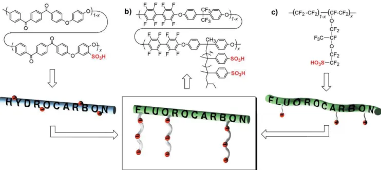
based on non-fluorinated, polyaromatic-based condensation polymers that contain ionic functionality in the form of sulfonic acid groups located along the polymer backbone (Fig. 1a). Generally, these polymers can achieve suitable conductivities only at high ion-exchange capacities (IECs), resulting in high water uptake and large membrane dimensional changes that are unsuitable for practical PEM applications. It has been
sug-–
[*] Dr. J. Ding, Dr. T. B. Norsten,[+]Dr. M. D. Guiver, J. Murphy
Institute for Chemical Process and Environmental Technology National Research Council of Canada
1200 Montreal Road, Ottawa, ON K1A 0R6 (Canada) E-mail: [email protected]
T. Astill, Dr. T. Navessin, Prof. S. Holdcroft
Institute for Fuel Cell Innovation, National Research Council 3250 East Mall, Vancouver, BC V6T 1W5 (Canada) T. Astill, Prof. S. Holdcroft
Department of Chemistry, Simon Fraser University 8888 University Drive, Burnaby, BC V5A 1S6 (Canada) Dr. B. L. Frankamp, Prof. V. M. Rotello
Department of Chemistry, University of Massachusetts Amherst, MA 01003 (USA)
[+] Present address: Xerox Research Center of Canada, 2660 Speakman Drive, Mississauga, Ontario L5K 2L1, Canada.
[**] NRCC Publication number 47874. This work was financially support-ed by the NRC Fuel Cell program; the MRSEC program at U. Mass. (DMR-0213695) is acknowledged for instrumentation. The authors are grateful to Dashan Wang for TEM analysis and Dr. Mike Day for his valuable assistance. T. B. N. is indebted to Roy Shenhar for help-ful discussions. Supporting Information is available online from Wi-ley InterScience or from the author.
A new class of comb-shaped polymers for use as a proton conducting membrane is presented. The polymer is designed to com-bine the beneficial physical, chemical, and structural attributes of fluorinated Nafion-like materials with higher-temperature, polyaromatic-based polymer backbones. The comb-shaped polymer unites a rigid, polyaromatic, hydrophobic backbone with lengthy hydrophilic polymer side chains; this combination affords direct control over the polymer nanostructure within the membrane and results in distinct microphase separation between the opposing domains. The microphase separation serves to compartmentalize water into the hydrophilic polymer side chain domains, resulting in effective membrane water management and excellent proton conductivities.
FULL
gested that these sulfonated polymers are unable to form de-fined hydrophilic domains, as the rigid polyaromatic backbone prevents continuous ionic clustering from occurring.[4] Intro-duction of ionic pendant side chains[5]or ionic blocks[6] into
these systems has shown promise in terms of materials perfor-mance, however the conductivity and membrane hydrody-namic properties typically remain lower relative to Nafion.
Nafion, on the other hand, is a statistical copolymer compris-ing a perfluorinated hydrophobic backbone that contains a number of short, flexible pendant side chains with single hydro-philic sulfonic acid groups (Fig. 1c). It is this delicate balance of hydrophobic–hydrophilic properties within the material, coupled with the increased mobility of the flexible ionic side chain, that, in the hydrated form, leads to networks of ionic channels through the material.[7]
Microstructural analysis of Nafion[8]and other newly
emerg-ing materials[9]has suggested that both chemical structure and nanoscale morphology of ionomer membranes dictate material performance. Although the microstructure of Nafion has been extensively examined, the exact morphology of Nafion remains controversial and is not entirely understood.[7] Furthermore,
the limited number of chemical variations of Nafion materials precludes a detailed systematic study linking polymer structure to materials properties.
Microphase separation of block copolymers can be used to create well-defined periodic microdomains of controlled mor-phology on the nanoscale. Microphase separation in block co-polymers arises from the incompatibility between the different covalently linked blocks. The ability to control domain size and morphology results from the precise synthetic control over the relative block volume fractions and the polydispersity of each block. This typically limits the synthetic methodologies used
for the preparation of these polymers to a limited number of monomers that can undergo living-type polymerizations.
Recently, research has shown that comb polymers are also capable of creating well-defined nanoscale morphologies.[10]
Many of the fundamental rules that govern block-copolymer microphase separation can be applied to comb polymers. This expands the range of available synthetic methodologies to include some non-living-polymerization techniques capable of producing functional polymers that can form microphase-sepa-rated morphologies.
Herein, we report on a series of highly fluorinated comb-shaped copolymers that can be used as PEMs. The goal of this study was to integrate the hydrophobicity of Nafion-like mate-rials, in the form of a fluorinated hydrophobic backbone, into a rigid, high-temperature polyaromatic backbone that contains flexible ionic side chains in order to create defined polymer microstructure within the PEM. In our method, we have com-bined the synthetic versatility of condensation copolymeriza-tion used to create robust, high-temperature polyaromatic backbones, with that of living anionic techniques, to create well-defined polymer side chains. The main-chain polymer is composed of a highly fluorinated poly(arylene)ether, while the side chain segments containing the ionic groups are composed of flexible, monodisperse poly(a-methyl)styrene (Fig. 1b).
Similar to previous polyaromatic PEM structures, this design incorporates the use of a semi-rigid polymer backbone capable of creating mechanically durable high-temperature mem-branes. This structure also incorporates a highly fluorinated backbone which, like Nafion, provides a high degree of hydro-phobicity and chemical stability to the material. Flexible, poly-ionic, hydrophilic side chains are employed to promote micro-phase separation, in order to create continuous ionic-channel
Adv. Funct. Mater.2006, 16, 1814–1822 © 2006 WILEY-VCH Verlag GmbH & Co. KGaA, Weinheim www.afm-journal.de 1815
Figure 1.Structures and graphical representations of a) a typical polyaromatic-based PEM displaying a rigid and sulfonated hydrocarbon backbone,
b) our hybrid material based on a highly fluorinated and rigid polyaromatic backbone with long, flexible pendant polymer side chains containing multiple sulfonic acid groups, and c) Nafion-based materials displaying a flexible perfluorinated backbone with short and flexible pendant side chains containing single sulfonic acid groups.
FULL
P
APER
networks. Unlike Nafion however, these side chains are relatively long and contain multiple sulfonic acid groups, which are designed to yield increased ionic domain interconnectivity and expected to provide better conductivity at low levels of hydra-tion.[6d,11] Because water is necessary for the efficient conduction of protons through a PEM, this set of structural de-sign features serves to direct water into the hydrophilic domains, maximizing the use of water within the membrane while at the same time maintaining the strong mechanical properties imparted by the hy-drophobic domains.
2. Results and Discussion
2.1. Synthesis of Comb-Shaped CopolymersPreparation of the polymer side chains, in the form of macromonomers, was achieved using anionic polymerization techniques. This produced monodisperse macromonomers that could be subse-quently copolymerized to form the de-sired aromatic-based backbone. Polymer-ization of a-methyl styrene produced macromonomers of
poly(a-methyl)styr-ene, which has been proven to be substantially more stable to oxidative degradation than previously reported polystyrene materials.[12]The length of the macromonomer was controlled
through the ratio of initiator to monomer, and was designed to be of a reasonable length (ca. 26 repeat units) to promote microphase separation. The living chain ends were capped with a functionalized bis-tert-butyldimethylsilyl ether (TBDMS) diphenylethylene (DPE) compound (Scheme 1) to produce functionalized living chain ends. An aliquot of the DPE living polymer was treated with methanol to produce a hydrogen-ter-minated macromonomer, while the remainder was treated with iodomethane to produce the corresponding methyl-terminated macromonomer. Subsequent removal of the TBDMS groups under mild acidic conditions quantitatively yielded the active bisphenol end-capped macromonomer. The hydrogen-termi-nated Mac-H (Scheme 1) was used to determine the molecular weight of the resulting end-capped polymer from the1H NMR
data, while the methyl-terminated Mac was used exclusively in all subsequent copolymerizations owing to the absence of the labile a-hydrogen.
The fluorine-containing, comb-shaped copolymers were pro-duced by condensation copolymerization of a mixture of hexa-fluorobispheryl A, decafluorobiphenyl, and Mac in the pres-ence of CsF in N,N-dimethylacetanide (DMAc) at 80 °C. The amount of side chain contained in the resulting copolymers could be controlled by varying the feed ratio of 6F-bisphenol A
(6F-BPA)/Mac. Copolymers containing side-chain weight frac-tions of 19 (1a), 25 (2a), and 38 % (3a) were produced from in-corporation of varying amounts of Mac.
It was critical to ensure that sulfonation was selective to the polymer side chains because random sulfonation, including in the backbone, would cause homogenous distribution of ionic groups throughout the material, resulting in poor microphase separation. Sulfonation of polymers 1a–3a with acetyl sulfate resulted in selective sulfonation of the poly(a-methyl)styrene side chains, producing the sulfonic acid containing polymers
1–3. The parent fluorinated poly(arylene)ether polymer
con-taining no poly(a-methyl)styrene side chain was treated under identical sulfonation conditions; these experiments yielded only starting material, confirming that the 6F-BPA group in the backbone is not susceptible to sulfonation under these con-ditions.
2.2. Characterization of Macromonomers and Comb-Shaped Copolymers
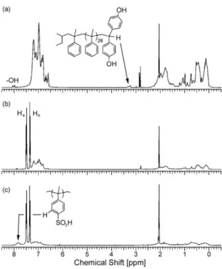
The terminal benzylic hydrogen at ca. 3.2 ppm of Mac-H (Fig. 2a) was used to determine the molecular weight of the macromonomer by integration against the remaining aromatic protons. The1H NMR spectrum for Mac was nearly identical
to Mac-H in all respects apart from the absence of the benzylic
Scheme 1.Synthesis of macromonomers and sulfonated comb-shaped copolymers.
FULL
P
resonance. The molecular weight obtained from1H NMR data for Mac-H correlated closely to the number-average molecular weight (Mn) of both Mac-H and Mac obtained by size
ex-change chromatography (SEC) analysis (Table 1); this suggests a high level of DPE capping of the living chain ends.
Figure 2b shows a typical1H NMR spectrum of a non-sulfo-nated comb-shaped copolymer. The aromatic region of the spectrum displays the distinct para-substitution pattern of the 6F-BPA in the backbone (Haand Hb,Scheme 1) as well as
in-corporation of the broad aromatic and aliphatic resonances of the poly(a-methyl)styrene side chains. The molar ratio of the side-chain repeat unit present in the copolymers was deter-mined by integrating the poly(a-methyl)styrene-based
aro-matic signals versus the isolated Ha doublet of 6F-BPA. The
molar ratios were then used to generate the Mac weight per-cents presented in Table 1. The NMR-generated Mac weight-percent values were in agreement with near full incorporation of Mac based on the initial monomer feed ratios. The SEC curves of copolymers 1a–3a were all monomodal and showed an increase in Mnas more Mac was incorporated into the
back-bone (Table 1).[13]
The aromatic region of the sulfonated polymers 1–3 (Fig. 2c) displayed the characteristic downfield shift (new broad reso-nance at ca. 7.8 ppm) due to the introduction of the sulfonic acid groups on the poly(a-methyl)styrene side chains.[14] The sulfonated copolymers 1–3 were generally soluble in polar solvents such as dimethylsulfoxide (DMSO) and acetone, but were insoluble in polar protic solvents such as water and methanol.
The glass-transition temperature (Tg) data for copolymers 1–3 were ambiguous owing to large residual-water endotherms.
Even after extensive drying and additional scans distinct Tgs
were not clearly discernable for the sulfonic acid form of copolymers 1–3. Soaking membranes 1–3 in sodium chloride solutions exchanged the sulfonic acid protons for sodium ions, producing the sodium sulfonate membranes 1(Na)–3(Na). The sodium salt forms of copolymers 1(Na)–3(Na) displayed a gradual increase in Tg with increasing side-chain content
(Table 1).
Figure 3a shows the thermogravimetric analysis (TGA) data for the backbone polymer, Mac, and copolymers 1a–3a. The on-set weight-loss temperature for the backbone polymer contain-ing no side chain was approximately 465 °C. As more side chain was introduced into the backbone the onset weight-loss temper-ature systematically approached that of Mac. It is also evident from the TGA traces that the side-chain content can be deter-mined by integration of the percent weight loss of the first step
Adv. Funct. Mater.2006, 16, 1814–1822 © 2006 WILEY-VCH Verlag GmbH & Co. KGaA, Weinheim www.afm-journal.de 1817
Figure 2.1H NMR data (d-acetone) of a) Mac-H, b) comb-shaped
copoly-mer 2a, and c) sulfonated comb-shaped copolycopoly-mer 2.
Table 1.Selected data for comb-shaped copolymers 1–3, Mac, and Nafion
117. Polymer Mac content x/wt [%][a] Sulfonate content [b] [%] Ion exchange capacity [c] [meq/g] Tg [°C] Mn[e] [g/mol] PDI [f] Mac 145 2810 1.09 1 .044/19 78 0.87 185 [d] 67 300 2.21 2 .059/25 88 1.40 188 [d] 77 300 2.02 3 .099/38 82 1.75 192 [d] 105 000 2.22 N117 0.96
[a] Determined by 1H NMR analysis on the pre-sulfonated copolymers
1a–3a. [b] Calculated from elemental analysis, [S(found)/S(calcd)] × 100, is a measure of sulfonate groups per a-methyl styrene unit. [c] Ion ex-change capacity determined by titration. [d] Sodium sulfonate form. [e] Values obtained from size exclusion chromatography (SEC) measure-ments in tetrahydrofuran (THF) prior to sulfonation. [f] Polydispersity in-dex (Mw/Mn; Mw: weight-average molecular weight) obtained from SEC.
Figure 3. TGA traces for a) comb-shaped copolymers 1a–3a, Mac, and
backbone polymer containing no Mac, and b) comb-shaped copolymers in the sulfonic acid form (1–3) and the sodium sulfonate form 1(Na)– 3(Na).
FULL
P
APER
transition for polymers 1a–3a (Fig. 3a). The onset weight-loss temperatures of the sulfonic acid containing polymers 1–3 are generally 100 °C lower than for the unsulfonated parent poly-mers, presumably due to the thermolysis of the sulfonic acid groups (Fig. 3b). The hydrolytic stability of membranes 1–3 were tested by boiling in water and 2MH2SO4for 48 h. There
was no observable decrease in proton conductivity after acid treatment, indicating that the sulfonic acid groups are stable to-wards these high-temperature hydrolytic conditions.
The onset weight-loss temperatures of the sodium sulfonate copolymers 1(Na)–3(Na) were markedly higher than the sulfo-nic acid containing copolymers 1–3 and ranged from 390 to 379 °C, respectively (Fig. 3b).
2.3. Morphological Analysis
Casting DMAc solutions of polymers 1–3 onto mirrored-glass substrates produced mechanically flexible and transpar-ent films approximately 80–100 lm thick. Small-angle X-ray scattering (SAXS) was used to study the modes of packing and periodicities between the microdomains of the comb-shaped copolymers. The membranes were soaked in a 0.5Msolution of
lead acetate to selectively stain the ionomeric domains for SAXS and transmission electron microscopy (TEM) analysis. As the amount of ionic side chain is increased from 19 to 38 % the q values corresponding to the first-order scattering peaks shift to larger values, indicative of smaller domain periodicities (Table 2). Hence, the copolymers with higher ionic side-chain contents yield narrower hydrophobic domains, resulting in
smaller ionic domain periodicities, as shown in Figure 4. This demonstrates that the ability to control the relative amount of side-chain polymer affords direct control
over the distance between alternating hydrophilic domains. The narrow peak profiles of the first order peaks for copoly-mers 1 and 2 indicate that the ionic do-mains are relatively uniform, while the broad first order peak for copolymer 3 suggests a wider distribution of domain periodicities. The SAXS profiles of the copolymers also display weak secondary scattering peaks, suggesting a level of longer-range order within the materials.
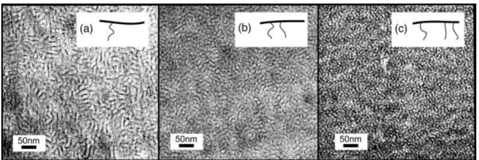
The SAXS data is directly correlated to the TEM images (Fig. 5), which
clearly show an increase of ionomeric content (dark regions) on increasing from 19 to 38 % side-chain content, and the systematic shrinkage of the hydrophobic regions (light re-gions). TEM also corroborates the SAXS data, providing a picture of the microphase-separated morphologies showing the distinct ionic domain connectivity. The TEM image for polymer 1 clearly shows phase-separated wormlike domains; the higher ordered reflection in the SAXS for polymer 1 is the most well-defined in this series of copolymers, with the peak maxima located very near 2q, suggesting the existence of domains containing lamellar morphologies. Multigraft polymers with random junction-point locations are known to be frustrated because different regions of the polymer prefer to form different morphologies as a result of the fluctuating local junction-point density, which leads to significant sup-pression of long-range order.[15] The lamellar domain shape
however, templates its own long-range order to a much greater degree than spheres or cylinders, which have more freedom to form disordered packing while filling space to a uniform density.[10a]
The broadness inherent in the higher ordered SAXS peaks for polymers 2 and 3 precludes definitively assigning specific microdomain morphologies to the structures. Nevertheless, the TEM image of polymer 3 clearly appears to contain nanome-ter-sized spotlike structures more consistent with a cylindrical domain shape, while the TEM image of polymer 2 contains morphological features inherent in the TEMs of both copoly-mers 1 and 3.
Table 2.Scattering vectors (q) and calculated ionic domain periodicities
for comb-shaped copolymers 1–3.
Polymer q[Å]–1 Periodicity [nm]
1 0.032 19.9
2 0.040 15.8
3 0.048 13.0
Figure 4.SAXS traces for lead-containing comb-shaped copolymer
mem-branes 1–3. Arrows point to higher ordered peaks indicative of longer-range order.
Figure 5.TEM images of lead-stained comb-shaped copolymer membranes displaying increasing
side-chain content: a) 1, b) 2, and c) 3.
FULL
P
2.4. Membrane Water Management and Proton Conductivity
Water management within the membrane is a critical factor in the performance of PEM materials. Water is the main vehi-cle by which protons are transported through the membrane,[16]
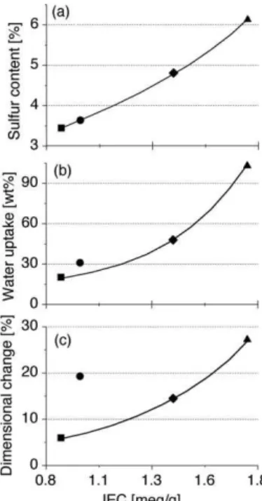
therefore it is an essential requirement to promote proton conductivity. Excessively high levels of water in the membrane however, can result in excessive dimensional changes (swell-ing) leading to failures in mechanical properties and, in ex-treme cases, membrane solubility in water. Water uptake is typically a function of the degree of sulfonation or the ion-ex-change capacity (IEC), which is a measure of the exion-ex-changeable protons in the material. Elemental analysis was used to deter-mine the degree of side-chain sulfonation for copolymers 1–3 and Nafion, while the corresponding IECs were determined by titration (Table 1 and Fig. 6). Figure 6a shows the expected monotonic increase in IEC in relation to the increasing amount of sulfonic acid groups (i.e., exchangeable protons) for the PEMs.
As the IEC increases, the weight-percent water uptake also increases in a fairly monotonic fashion for copolymers 1–3 and Nafion 117 (Fig. 6b). However, the dimensional change as a function of IEC is lower for the comb-shaped copolymer mate-rials versus Nafion. At similar IEC values, Nafion exhibits more than double the dimensional change in the lengthwise di-rection as compared with the comb-shaped copolymer materi-als (Fig. 6c). Swelling in these materimateri-als is slightly anisotropic, exhibiting an increased (ca. 30 %) dimensional change in the
width direction (i.e., through the membrane) when compared to the lengthwise direction. Nevertheless, the water uptake and swelling of these materials is markedly less than in typical aro-matic PEMs sulfonated along the backbone,[17]demonstrating the ability of this structured material to more-efficiently com-partmentalize water. We attribute this to the unique morpho-logical structure that directs water into the narrow hydrophilic domains while the thicker alternating hydrophobic domains, particularly in polymers 1 and 2, serve to maintain both the structural and dimensional stability of the material. This phe-nomenon is akin to covalent crosslinking of polymers to main-tain membrane dimensional stability.[18]In this case however, the polymer microstructure comprising alternating hydropho-bic domains achieves the same goal based on the macromolec-ular self-organization of the designed materials. This idea is further substantiated by a recent study employing an identical fluorinated polymer with sulfonic acid groups located directly on the backbone—these membranes exhibited significantly higher water-uptake values and proved to be substantially less conductive relative to Nafion.[19]
Figure 7 shows that the comb-shaped copolymers also display excellent proton conductivities over the temperature ranges studied. The increase in conductivity is correlated to the
in-crease in side-chain content and IEC values for polymers 1–3. The higher ionic side-chain content results in smaller backbone (hydrophobic) domains, as seen in the TEM and SAXS data. This ultimately results in better-connected ionic domains lead-ing to the excellent conductivities observed for these materials.
2.5. Comb-Shaped Copolymer Membrane Electrode Assemblies
With copolymers 1–3 exhibiting unique microstructures and possessing suitable membrane characteristics with regard to thermal properties, water uptake, dimensional stability, and proton conductivity, the performance of the copolymers was explored in an operating fuel cell.
Adv. Funct. Mater.2006, 16, 1814–1822 © 2006 WILEY-VCH Verlag GmbH & Co. KGaA, Weinheim www.afm-journal.de 1819
Figure 6.a) Sulfur weight-percent data determined by elemental analysis,
b) weight-percent water uptake data at 80 °C, and c) the corresponding lengthwise dimensional change data at 80 °C, as a function of IEC for co-polymer membranes 1 (䊏), 2 (䉬), 3 (~), and Nafion 117 (䊉).
Figure 7.Proton conductivity data as a function of temperature measured
in water for comb-shaped copolymer membranes 1–3 and Nafion 117.
FULL
P
APER
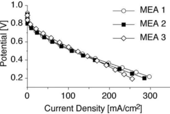
Polymer 2 was selected for the preliminary measurements owing to its intermediate values of IEC and proton conductiv-ity, and its corresponding high dimensional stability. Two mem-brane electrode assemblies (MEAs) were fabricated, MEA-2 and MEA-3—their compositions are listed in Table 3. An MEA containing Nafion ionomer and Nafion 115 membrane (MEA-1) was used for comparison.
Figure 8 shows the fuel-cell performance for the MEAs at 30 °C. The polarization curves of MEAs containing sulfonated comb-shaped copolymer exhibit similar performance to Nafion-based MEAs, particularly in the kinetic (OCP–0.75 V; OCP:
open-circuit potential) and ohmic (0.75–0.40 V) regions. Under high-current-density conditions (0.40–0.20 V), a slight drop in performance is observed. In this region, high current density is limited by the transport of the reactant gas to the catalytic sites. MEA-1 and MEA-2 were tested at higher temperatures (80 °C) with Nafion gas diffusion electrodes (GDEs), however delami-nating of the MEA occurred over time due to inadequate adhe-sion of the electrode/membrane interface. Further study on the effect of the comb-shaped copolymers on the mass-transport pa-rameters in PEMFCs is ongoing. It is noteworthy that the pre-liminary results are based on MEA-fabrication procedures that have been optimized for Nafion-based MEAs and not opti-mized for the comb-shaped copolymer MEAs. The high Tgof
this material would require higher hot-pressing temperatures, above the 160 °C that was used in this study, to increase the ad-hesion of the MEA layers. We are currently exploring this possi-bility of employing the more thermally stable sodium sulfonate forms of the copolymers for hot-pressing at higher
tempera-tures. Nevertheless, the data presented illustrates that the comb-shaped-polymer MEAs can yield a fuel-cell performance similar to that of Nafion. Further studies on the optimization of condi-tions and the performance at elevated temperatures are cur-rently underway in our laboratories.
3. Conclusions
In summary, a series of highly fluorinated polyaromatic-based comb-shaped copolymers were prepared that display advantageous conductivity and membrane hydrodynamic prop-erties as compared to most sulfonated arylene main-chain poly-mers. It appears that the unique polymer chemical structure re-sulting in microphase separation between extreme opposing hydrophobic and hydrophilic domains is responsible for the high proton conductivities and corresponding low dimensional changes observed. Further MEA investigations at elevated temperatures under reduced humidity conditions will be con-ducted to determine the effect of proton channeling in these materials. A thorough examination of membrane stability is also warranted to test the general applicability of these materi-als in PEMFCs.
4. Experimental
4.1. MaterialsDecafluorobiphenyl was purchased from Oakwood Products Incor-porated (West Columbia, SC) and was vacuum sublimed before use. 6F-BPA was purchased from Aldrich and recrystallized twice from tol-uene. Tetrahydrofuran (THF) for anionic polymerizations was distilled from purple benzophenone/sodium ketyl under dry argon. The a-meth-yl styrene was stirred over CaH2(in a flame-dried distillation
appara-tus) for 24 h and vacuum distilled immediately before use. sec-Butyl lithium (s-BuLi; Aldrich 1.4Min hexanes) was used as received. Anhy-drous grade DMAc was used for film casting and all condensation poly-merizations. All reagent purifications and polymerizations were per-formed under dry argon atmosphere using standard Schlenk techniques. All other solvents and reagents (obtained from Aldrich) were reagent grade and were used as received.
4.2. Instrumentation
1
H NMR spectra were obtained on a Varian Unity Inova NMR spec-trometer operating at a resonance frequency of 400 MHz. Deuterated acetone or deuterated dimethylsulfoxide (DMSO-d6) were used as the
NMR solvents. Molecular weights (Mn) of the unsulfonated polymers
were determined by size exclusion chromatography using a Waters 515 HPLC pump coupled to a Waters 410 differential refractometer detec-tor and a Waters 996 photodiode array detecdetec-tor operating at a wave-length of 260 nm. For the macromonomer, a set of Microstyragel columns (100, 500, 1000 Å) were used, while a different set of Microstyr-agel columns (103, 104, 105Å) were employed for the copolymer
materi-als. All columns were calibrated with polystyrene standards bracketing the areas of interest, employing THF as the solvent. A TA Instruments thermogravimetric analyzer (TGA) Instrument model 2950 operating in dynamic high-resolution mode (heating rate = 20 °C min–1,
resolu-tion = 4, sensitivity = 1) was used for measuring weight loss and polymer decomposition temperatures (Td). A TA Instruments differential
scan-Table 3.Compositions of MEAs used for PEMFC evaluation.
Sample Cathode
(30 wt % ionomer)
Membrane Anode
(30 wt % ionomer)
MEA-1 Nafion Nafion 115 Nafion
MEA-2 Nafion Polymer-2 Nafion
MEA-3 Polymer-2 Polymer-2 Polymer-2
Figure 8.Single-cell polarization data for MEAs containing comb-shaped
copolymers (MEA-2 and MEA-3), and a Nafion-based MEA (MEA-1); 30 °C cell temperature, 0.1 L min–1humidified H
2and air, and ambient pressure.
FULL
P
ning calorimeter (DSC) model 2920 calibrated with tin (Sn) at 231.93 °C and zinc (Zn) at 419.53 °C operating at 10 °C min–1was used for
measur-ing glass-transition temperatures (Tg). Both the DSC and TGA
mea-surements were conducted under a nitrogen atmosphere.
4.3. Anionic Polymerization
Bis-tert-butyl Dimethylsilyl (TBDMS) Macromonomer
(TBDMS-Mac-Hand TBDMS-Mac): The TBDMS-protected diphenylethylene
was prepared as previously described using a modified Wittig proce-dure [20]. A typical anionic polymerization consisted of charging a flame-dried, septum-sealed, evacuated 250 mL round-bottomed flask with 100 mL of THF. a-Methyl styrene (10 g, 0.085 mol) was then in-troduced (via syringe) and the solution was cooled to –78 °C in a dry-ice–acetone bath. A calculated amount of s-BuLi (3.6 mL, 0.005 mol) was then added to the reaction flask all at once via syringe. The orange/ red solution was rapidly stirred at –78 °C for 20 min at which point a THF solution (10 mL) of the TBDMS-protected diphenylethylene end cap (2.16 g. 0.006 mol) was cannulated into the reaction mixture using reduced pressure in the reaction flask. The mixture was allowed to re-act for 3 h at –78 °C at which point an aliquot was removed by syringe and quenched with degassed MeOH, yielding TBDMS-protected Mac-H. Iodomethane was added to the remainder of the reaction mixture (1.3 g, 0.009 mol) producing TBDMS-protected Mac. The mixture was allowed to warm to ambient temperature, precipitated into excess MeOH, collected by vacuum filtration, and vacuum dried.
Bisphenol Macromonomer (Mac-H and Mac): Deprotection of TBDMS group was achieved by refluxing the protected macromono-mer in 2 % HCl/THF solution for 24 h. The THF was removed under reduced pressure and the residue polymer was taken up in CH2Cl2.
The organic layer was washed three times with a 5 % NaOH solution followed by dilute HCl and then a saturated brine solution. The solu-tion was dried over anhydrous magnesium sulfate, precipitated into ex-cess MeOH, and vacuum dried.
4.4. Condensation Copolymerization of Comb-Shaped Copolymers 1a–3a
A typical polymerization incorporating 25 % macromonomer con-sisted of charging an argon purged three-neck round-bottomed flask equipped with a thermometer with decafluorobiphenyl (401 mg, 1.2 mmol), 6F-BPA (370 mg, 1.1 mmol), and phenol macromonomer (252 mg, 0.09 mmol). DMAc (8 mL) and CsF (435 mg, 2.9 mmol) were then added to the flask, which was gently evacuated under pressure and back-filled with argon. The reaction was stirred at 80 °C for 16–20 h, after which the thick solution was filtered through a cotton plug and precipitated into an excess MeOH solution with rapid stirring. Small amounts of cyclic oligomers produced were removed by repreci-pitating the polymer in a 1:1 mixture of acetone/MeOH. The polymer was then dried under vacuum for 24 h at 65 °C.
4.5. Sulfonation of Comb-Shaped Copolymers 1–3
A fresh 1Msolution of acetyl sulfate was prepared before each sulfo-nation reaction by slowly adding 1.4 mL of sulfuric acid to a 3–5 °C stirring solution of 3.8 mL of acetic anhydride dissolved in 20 mL of di-chloroethane. A 3–5 % solution of the comb polymer in dichloroethane was heated to 50 °C, after which an amount of acetyl sulfate corre-sponding to 1.25 molar equivalents/per a-methyl styrene repeat unit was added. After 1 h the solution became turbid and a gel-like precipi-tate began to form. After 4 h methanol was added to quench any remaining sulfonating reagent and the solvent was removed under
re-duced pressure. The polymer residue was washed repeatedly with dis-tilled water until the supernatant was of neutral pH. The sulfonated polymer was then dried under vacuum for 24 h at 65 °C.
4.6. Membrane Preparation
A certain amount of sulfonated comb copolymer (0.45 g) was dis-solved in 8 mL of DMAc and filtered through cotton plug that had been pre-washed with fresh DMAc. The solution was filtered directly onto a mirrored and leveled glass plate having a circular mirrored-glass retaining wall (diameter = 8 cm). The plate was placed inside a covered container and dried at 50 °C under a constant purge of argon for two to four days. The thickness of the membrane films ranged from 80 to 100 lm. Thicknesses were measured using a Mitutoyo digital microme-ter.
4.7. Water-Uptake and Dimensional-Change Measurements
Membrane films were dried under vacuum at 65 °C for 48 h prior to the measurements. After measuring the lengths (0.5 cm × 5 cm) and weights of dry membranes, the sample films were soaked in deionized water for 24 h at predetermined temperatures. Before measuring the lengths and weights of hydrated membranes, any surface-bound water was removed from the membrane by blotting the surface with a filter paper. The water uptake content was calculated according to the equa-tion [water uptake (%) = (xwet– xdry)/xdry× 100 %], where xdry and
xwetare the masses of dried and wet samples respectively. The dimen-sional change was calculated from strips of films ca. 5 cm in length according to the equation [dimensional change (%) = (lwet– ldry)/
ldry× 100 %], where ldryand lwetare the lengths of dry and wet samples,
respectively.
4.8. Ion Exchange Capacity
The IECs of the membranes were determined by titration. A piece of membrane (4 cm × 4 cm) in the acidic form was immersed in 40 mL of 2.0MNaCl solution for 24 h. Solutions were titrated with 0.025M NaOH solution to a phenolphthalein end point. After titration, the sample was rinsed with distilled water and dried under vacuum at 65 °C until a constant weight was achieved (48 h). The IEC was calculated ac-cording to the equation: [IEC (meq g–1) = (VNaOH× CNaOH)/Ws], where
Wsis the dry weight (mg) of the sample and VNaOHand CNaOHare the
volume (mL) and molar concentration of NaOH solution, respectively.
4.9. Transmission Electron Microscopy
Membranes in the sulfonic acid form were immersed in 0.5Mlead ac-etate solution for 48 h and rinsed with water in order to stain the ionic domains. A 1 mm × 5 mm strip was then cut from the membrane. The thin sample was embedded in bimodal polystyrene (Aldrich) by placing the strip in a glass vial containing several polystyrene (PS) beads and heating at 120 °C until the PS completely embedded the sample. The glass vial was then shattered and the embedded polymer sample was collected. Thin films (40–50 nm) of the embedded polymer samples were prepared using an ultramicrotome (Ultracut-E, Reichert-Jung) fitted with a Diatome diamond knife. The slices were picked up with 400 mesh carbon coated copper grids for TEM analysis. The samples were analyzed using a Philips CM20 STEM equipped with a Gatan Ul-traScan 1000 charge-coupled device (CCD) camera and INCA Energy TEM 200 EDX spectrometer operating at 120 kV.
Adv. Funct. Mater.2006, 16, 1814–1822 © 2006 WILEY-VCH Verlag GmbH & Co. KGaA, Weinheim www.afm-journal.de 1821
FULL
P
APER
4.10. Small-Angle X-ray Scattering
Cu Ka X-rays (1.54 Å) were generated in an Osmic MaxFlux source with a confocal multilayer optic (OSMIC, Inc.). Images were taken with a Molecular Metrology Incorporated camera consisting of a three-pinhole system, 150 cm sample-to-detector distance (calibrated using silver behenate), and a 2D multiwire proportional detector (Molecular Metrology, Inc.). The entire X-ray path length was evacuated from the optic to the detector in order to reduce the background from air scat-tering. This setup allowed neglecting the correction for background scattering as proved by experiment. 2D images were reduced to 1D form using angular integration. Scattering vectors (q) were calculated from the scattering angles (h) using q = 4p sinh/k, and domain periodici-ties (D) were calculated from Gaussian fits to the principal scattering maxima of the Lorentz-corrected intensities using D = 2p/q.
4.11. AC Impedance Spectroscopy
All conductivity measurements were performed in the longitudinal direction in deionized Milli-Q water (18 MX resistivity). Membrane samples (20 mm × 10 mm) were acidified in 2MHCl, rinsed thoroughly, and soaked in distilled water for a minimum of 24 h before use. Vari-able temperature measurements were performed in a thermally con-trolled stainless-steel vessel employing a two-electrode (platinum) AC impedance technique using a Solartron 1260 frequency-response ana-lyzer. Spectra were recorded between 102and 107Hz with ten points
per decade at a maximum perturbation amplitude of 100 mV. All con-ductivities (r) were calculated using the relation r = d/RS, where d and Sare the dry thickness and face area of the sample, respectively, and R was derived from the low intersect of the high-frequency semi-circle on the complex impedance plane with the Re(Z) axis by fitting the data
based on the equivalent circuit Rs(C-Rp) employing the corresponding
instant fit function in the Zview 2.80 software by Scribner Associates Inc.
4.12. MEA Fabrication
Gas diffusion electrodes (GDEs) were fabricated by spray deposi-tion of catalyst ink onto carbon paper (Toray, TGPH-060, containing 10 wt % polytetrafluoroethylene, E-TEK). The catalyst ink was pre-pared by sonicating a mixture of 20 wt % Pt/Vulcan XC-72 (E-TEK, De Nora N. A., Inc.), ionomer solution (5 wt % Nafion in alcohols/ water or comb copolymer 2 in DMSO) and isopropyl alcohol for 90 min at room temperature. After spray deposition, the GDEs con-taining the polymer were floated on 0.5MH2SO4 for 4 h to remove
trace DMSO impurities. The GDEs were subsequently dried for one hour at 80 °C. The electrodes fabricated contained 0.4 mg Pt/cm2and
30 wt % ionomer (Nafion or Polymer-2). Membranes were sandwiched between two GDEs (5 cm2) from the same batch and the assembly
hot-pressed at 135 °C (Nafion) or 160 °C (comb copolymer 2) and 135 kg cm–2force for 90 s. MEAs were tested in a 5 cm2single-cell
fix-ture (Fuel Cell Technologies, Inc.) using a fuel-cell test station (Medu-sa, Teledyne Inc.) at 30 °C. The gas inlets (H2and air) were humidified
at 40 °C and supplied at a flow rate of 100 mL min–1at ambient pres-sure. Before obtaining polarization data, the cell was equilibrated at the open-circuit potential (OCP) for ca. 2 h with humidified H2and
air, following this the MEA was conditioned by operating at constant potential for 15 min in increments of 0.05 V from 0.75 to 0.60 V.
Received: November 1, 2005 Final version: January 25, 2006 Published online: August 8, 2006
–
[1] A. Heinzel, B. C. H. Steele, Nature 2001, 414, 345. [2] M. Rikukawa, K. Sanui, Prog. Polym. Sci. 2000, 25, 1463.
[3] M. A. Hickner, H. Ghassemi, Y. S. Kim, B. R. Einsla, J. E. McGrath, Chem. Rev. 2004, 104, 4587.
[4] K. D. Kreuer, J. Membr. Sci. 2001, 185, 29.
[5] L. E. Karlsson, P. Jannasch, J. Membr. Sci. 2004, 230, 61.
[6] a) H. Ghassemi, G. Ndip, J. E. McGrath, Polymer 2004, 45, 5855. b) H. Ghassemi, W. Harrison, T. A. Zawodzinski, Jr., J. E. McGrath, Polym. Prepr. (Am. Chem. Soc., Div. Polym. Chem.) 2004, 45, 68. c) Y. Yang, Z. Shi, S. Holdcroft, Macromolecules 2004, 37, 1678. d) X. Yu, A. Roy, J. E. McGrath, Prepr. Symp.–Am. Chem. Soc., Div. Fuel Chem. 2005, 50, 577.
[7] K. A. Mauritz, R. B. Moore, Chem. Rev. 2004, 104, 4535.
[8] M. Fujimura, T. Hashimoto, H. Kawai, Macromolecules 1982, 15, 136. [9] a) Y. Yang, S. Holdcroft, Fuel Cells 2005, 2, 117. b) J. Ding, C. Chuy,
S. Holdcroft, Macromolecules 2002, 35, 1348. c) Y. A. Eladb, C. W. Walker, F. L. Beyer, J. Membr. Sci. 2004, 231, 181. d) J. Won, H. H. Park, Y. J. Kim, S. W. Choi, H. Y. Ha, I. H. Oh, H. S. Kim, Y. S. Kang, K. J. Ihn, Macromolecules 2003, 36, 3228. e) L. Rubatat, Z. Shi, O. Diat, S. Holdcroft, B. J. Frisken, Macromolecules 2006, 39, 720. [10] a) M. Xenidou, F. L. Beyer, N. Hadjichristidis, S. P. Gido, N. B. Tan,
Macromolecules 1998, 31, 7659. b) Y. Zhu, R. Weidisch, S. P. Gido, G. Velis, N. Hadjichristidis, Macromolecules 2002, 35, 5903.
[11] S. J. Paddison, Annu. Rev. Mater. Res. 2003, 33, 289.
[12] a) G. Hübner, E. Roduner, J. Mater. Chem. 1999, 9, 409. b) R. A. As-sink, C. Arnold, Jr., R. P. Hollandsworth, J. Membr. Sci. 1991, 56, 143. [13] See Supporting Information.
[14] J. C. Yang, M. J. Jablonsky, J. W. Mays, Polymer 2002, 43, 5125. [15] S. Qi, A. K. Chakraborty, H. Wang, A. A. Lefebvre, N. P. Balsara,
E. I. Shakhnovich, M. Xenidou, N. Hadjichristidis, Phys. Rev. Lett. 1999, 82, 2896.
[16] K. D. Kreuer, A. Rabenau, W. Weppner, Angew. Chem. Int. Ed. Engl. 1982, 21, 208.
[17] P. Xing, G. P. Robertson, M. D. Guiver, S. D. Mikhailenko, S. Kalia-guine, Macromolecules 2004, 37, 7960.
[18] a) J. A. Kerres, Fuel Cells 2005, 2, 230. b) P. Jannasch, Fuel Cells 2005, 2, 248.
[19] H. C. Lee, H. S. Hong, Y. M. Kim, S. H. Choi, M. Z. Hong, H. S. Lee, K. Kim, Electrochim. Acta 2004, 49, 2315.
[20] R. P. Quirk, Y. Wang, Polym. Int. 1993, 31, 51.