HAL Id: hal-02061687
https://hal.archives-ouvertes.fr/hal-02061687
Submitted on 7 May 2020HAL is a multi-disciplinary open access archive for the deposit and dissemination of sci-entific research documents, whether they are pub-lished or not. The documents may come from teaching and research institutions in France or abroad, or from public or private research centers.
L’archive ouverte pluridisciplinaire HAL, est destinée au dépôt et à la diffusion de documents scientifiques de niveau recherche, publiés ou non, émanant des établissements d’enseignement et de recherche français ou étrangers, des laboratoires publics ou privés.
Influence of solidification induced composition gradients
on carbide precipitation in FeNiCr heat resistant steels
M. Roussel, X. Sauvage, M. Perez, D. Magne, A. Hauet, A. Steckmeyer, M.
Vermont, T. Chaise, M. Couvrat
To cite this version:
M. Roussel, X. Sauvage, M. Perez, D. Magne, A. Hauet, et al.. Influence of solidification induced composition gradients on carbide precipitation in FeNiCr heat resistant steels. Materialia, Elsevier, 2018, 4, pp.331-339. �10.1016/j.mtla.2018.10.010�. �hal-02061687�
1 Influence of solidification induced composition gradients on carbide precipitation in FeNiCr heat resistant steels
M. Roussel1, 2, X. Sauvage1*, M. Perez3, D. Magné1, A. Hauet1, A. Steckmeyer2, M. Vermont1, 2, T. Chaise4,
M. Couvrat2
1 Normandie Univ, UNIROUEN, INSA Rouen, CNRS, Groupe de Physique des Matériaux, 76000 Rouen,
France
² Manoir Industries, 12 Rue des Ardennes - BP 8401 – Pitres, 27108 Val de Reuil, France
3 Univ. Lyon – INSA Lyon - MATEIS, UMR CNRS 5510 – 69621 Villeurbanne Cedex, France 4 Univ. Lyon – INSA Lyon - LaMCoS, UMR CNRS 5259 – 69621 Villeurbanne Cedex, France
*Corresponding author : xavier.sauvage@univ-rouen.fr
Keywords: Steel; precipitation; carbide; modeling; chemical gradient; solidification
Abstract
Secondary precipitation of Cr-rich carbides in heat resistant austenitic stainless steels has been investigated both experimentally and using finite element simulations. The microstructural evolutions in two commercial grades were characterized using electron microscopy. A special emphasis was given on the peculiar spatial distribution of M23C6 secondary carbides exhibiting precipitate free zones
surrounding primary carbides, and high density precipitate zones extending with longer aging times. Solidification induced chemical composition gradients were clearly exhibited in the as-cast alloys with significant chromium depletion in the vicinity of primary M7C3 carbides. It is then proposed that these
gradients play a major role in the secondary precipitation mechanism. Classical nucleation and growth theories have been adapted to account for (i) the flux of solutes with large difference in diffusion coefficients, (ii) the initial composition gradients in the matrix and, (iii) the chemical driving force for nucleation and growth of M23C6 carbides. Within this framework, the whole kinetics has been
reproduced. It clearly shows that the spatial distribution of secondary carbides that play a key role in the creep resistance of these alloys is the result of a complex interaction between initial composition gradients in as-cast alloys and solute flux resulting from phase transformation during aging.
2 1. Introduction
Heat resistant steels used in cracking or reforming furnaces have to face harsh service conditions including high temperatures (from 750°C up to 1100°C), oxidizing environment on the external surface of pipes and in some cases carburizing on the inside [1–4]. Steels with high chromium contents (>25wt.%) have been designed to resist against oxidation but, since a significant creep resistance is also required, a significant amount of nickel has also been introduced to avoid the ferritic structure and to obtain fully austenitic steels [3]. Pipes of such FeNiCr steels (known as HK or HP grades) are typically produced using centrifugal casting. During solidification, large columnar grains with a dendritic structure are typically created. Dendrites from the fcc austenitic phase are surrounded by micrometer scale eutectic carbides. These carbides, called primary carbides, are MC (Nb or Ti rich) or M7C3 (Cr rich) carbides [5]. It is important to note that these materials are often directly used in as-cast
conditions but M7C3 primary carbides are not stable in the temperature range of applications and
transform into the stable M23C6 [6]. This transformation is accompanied by the precipitation of
secondary carbides which typically nucleate and grow within the austenitic matrix [7]. It has been demonstrated that secondary carbides play a very important role since they significantly improve the creep resistance by hindering dislocations [8–12]. Therefore controlling the number density, the volume fraction and the size distribution of these carbides is a key issue to improve the creep resistance.
The transformation of M7C3 in M23C6 and the subsequent secondary carbide precipitation within the
austenitic matrix have been studied in many systems like high Cr steels [13–16], Ni superalloys [17,18] or austenitic stainless steels [5,7,19–21]. It is important to note that when the primary M7C3 carbides
transform into M23C6, their carbon content is significantly reduced. Even though after aging the original
macrostructure looks relatively unchanged under the optical microscope where the micrometer scale primary M7C3 are transformed into M23C6, the carbon excess is released in the austenitic matrix giving
rise to a homogeneous nucleation and growth of submicrometer M23C6. These carbides exhibit a
crystallographic structure with a super lattice very close to the fcc structure of the austenitic matrix (with an average mismatch of only 1.3 % parallel to the {111} planes) and therefore grow with a cube on cube orientation. Due to the elastic distortions resulting from the misfit, it has been shown that the nucleation barrier could be reduced in the vicinity of already existing carbides, leading to some typical rows of carbides [7]. It has also been often reported that M23C6 carbides easily nucleate along
dislocations where the elastic energy associated with the lattice distortion is reduced [19].
There are however few interesting and intriguing features about the peculiar secondary carbide distribution and growth mechanisms that has not been fully clarified yet. Indeed, despite the great variety of heat resistant steels, aged microstructures often exhibit: i) a precipitate free zone (PFZ) surrounding primary carbides, ii) a high density precipitate zone (HPZ) few micrometers away from
3 primary carbides, iii) a low density precipitate zone (LPZ) in the austenitic grain interior [22–26]. The extension of these different zones depends on the alloy composition, casting conditions and ageing conditions but they are always observed. Thus, the aim of the present work is to carefully examine the structure of aged heat resistant steels to provide some input in a model that takes into account chemical gradients and diffusion fluxes (especially the flux of carbon atoms released by the transformation of primary carbides) to account for the complex microstructural evolution resulting from secondary precipitation in heat resistant steels.
In this paper, we investigate the precipitation of M23C6 secondary carbides in the vicinity of existing
primary carbides by Scanning Electron Microscopy (SEM) and Transmission Electron Microscopy (TEM). A simple precipitation model based on classical nucleation and growth theories is then proposed to analyze the precipitation kinetics of secondary carbides and to explore the role of solidification induced chemical gradients revealed around primary carbides.
2. Experimental details
Two different austenitic heat resistant steels produced by Manoir Industries were investigated in the present study. Centrifugally cast tubes made of these materials are typically used in cracking furnaces [2]. The nominal composition of these two commercial steels is given in table 1. They have been selected with similar carbon content but a significant difference in Ni/Cr ratio. It is also interesting to note that steel 1 contains a small amount of Nb while steel 2 contains some Al and Ta. Nb and Ta are known to form MC carbides (M being Nb or Ta) and thus slightly affect the volume fraction of M7C3
and M23C6 carbides, however the aim of the present study was to show that the detailed mechanisms
of the secondary precipitation during aging could be captured for most commercial grades and that it does not significantly depend on small variations of the volume fraction of carbides. Artificial aging experiments were carried out in furnaces with a natural air environment at 750°C. This temperature is lower than most of industrial applications, but it has been selected to slow down the kinetics and capture the different stages of the secondary precipitation mechanism (observations done after 16, 64 and 112h of aging have been selected for the present manuscript). Equilibrium phases and their temperature range of stability have been computed with Thermocalc software using the TCFe-6 data base (Fig. 1). In both alloys, the M7C3 phase is stable only just below the liquidus temperature, but at
750°C the only stable Cr-rich carbide is M23C6. It is important to note that below 800°C a significant
equilibrium volume fraction of G phase and phase is exhibited for steel 1 and steel 2, respectively. However, these phases nucleate only after very long aging time [20] and thus does not significantly affect the secondary precipitation mechanisms.
To follow the transformation of primary M7C3 carbides and the resulting precipitation of M23C,
4 LEO 1530 XB operating at 15kV. Images were recorded using a secondary electron detector and a 60 m aperture. Prior to SEM investigation samples were mechanically polished with ¼ m diamond paste. In order to image primary and secondary carbides, the samples were chemically etched using either an oxalic acid solution (preferential etching of the austenitic matrix) or an A2 solution from Struers (preferential etching of Cr-rich carbides). TEM observations were carried out with a probe corrected JEOL ARM-200F operated at 200kV. Analytical data were collected by scanning TEM (STEM) with a probe size of 0.2 nm and a convergence angle of 34 mrad. Elemental mapping was carried out using Energy Dispersive X-ray Spectroscopy (EDS) with an Oxford Instruments X-max detector, which has a solid angle of 0.7 sr. TEM samples were prepared from 3 mm disks thinned down to electron transparency with a twin jet electropolisher (Tenupol 5 from Struers) using a solution of 10% perchloric acid - 90% acetic acid at +14°C and a voltage of 20V. To obtain better quality samples, a final polishing was carried out by ion milling (Gatan PIPS II operated at 3keV during 5 minutes with ±3° inclination angle).
5 Figure 1: Thermocalc prediction of equilibrium molar fractions of phases in steel 1 (a) and steel 2 (b) as
a function of temperature. M7C3 corresponds to the Cr-rich primary carbides. M23C6 corresponds to the
Cr-rich secondary carbides. NbC corresponds to the Nb-rich primary carbides. corresponds to an Fe- and Cr-rich intermetallic phase. G corresponds to the G-phase, an intermetallic silicide.
3. Experimental Results
Microstructures of steel 1 and steel 2 after aging at high temperature are typical for such heat resistant steels with large primary eutectic carbides (several micrometers in size) located between austenitic dendrite arms (width ranging from 30 to 60 m). The evolution of the microstructure near primary carbides is shown in Fig. 2 for aging times up to 112 h at 750°C. In the as-cast state, large and lamellar eutectic M7C3 carbides are exhibited (darkly imaged on Fig. 2(a) and crystallographic structure
confirmed using selected area electron diffraction (SAED) in the TEM) while the matrix is free of any precipitate. Then, after only 16 h at 750°C (Fig. 2(b)), numerous small carbides nucleate in the matrix within a distance of only a few microns from primary carbides. The structure and the orientation relationship of these carbides has been checked using TEM (Fig. 3), they are M23C6 carbides as
expected. Further annealing, up to 64 h leads to an apparent growth of secondary carbides (brightly imaged in Fig. 2(c)) that have nucleated earlier while new carbides seem to nucleate in the matrix (top left of Fig. 2(c)). A closer look at higher magnification in such a region clearly reveals that some of the secondary M23C6 carbides have nucleated on linear defects, supposedly dislocations (Fig. 2(e)) as
reported by other authors for similar steels [19]. Then, further annealing (Fig. 2(d)) leads to a significant extension of the secondary precipitation zone and also to further growth of M23C6 carbides. It is
interesting to note that, as already reported by other authors [3], secondary carbides do not nucleate on primary carbides (which are carbon reservoirs) but in the matrix at a short distance of a few micrometers, leaving a PFZ.
6 Figure 2: SEM images (secondary electron detector) showing the microstructure of steel 1 in the as-cast
state (a) and after aging at 750°C for 16 h (b), 64h ((c) and (e)) and 112h (d). Precipitation of M23C6
secondary carbides in the vicinity of primary carbides is clearly exhibited for the early stage of aging, and it progressively extends in the matrix. The higher magnification image recorded in the austenitic matrix (e) reveals smaller secondary carbides and show that some of them nucleated along a linear defect (supposedly a dislocation). For images a) and b) the samples were etched using A2 solution from Struers to brightly image the matrix and for images c), d) and e) the samples were etched using oxalic acid solution to brightly image the carbides). In Fig.2(a) the inset is a SAED pattern collected on a primary carbide and that demonstrates that these carbides exhibit a Cr7C3 structure.
7 Figure 3: TEM images (Bright field, High resolution and SAED pattern in (001) zone axis) showing
secondary M23C6 carbides that have nucleated and grown during aging at 750°C for 112h in the
austenitic matrix of steel 1 with a cube on cube orientation relationship.
Figure 4: SEM images (secondary electron detector) showing the microstructure of steel 2 (etched using
oxalic acid solution to brightly image carbides) after aging at 750°C during 16 h (a), 64h (b) and 112h (c). Precipitation of M23C6 secondary carbides in the vicinity of primary carbides is clearly exhibited for
8 A very similar microstructure evolution was observed for steel 2 (Fig. 4) with also a progressive growth of the secondary precipitation zone and a PFZ near primary carbides. The microstructural differences of the two investigated steels as observed by SEM are quantitatively plotted as a function of the annealing time in Fig. 5. The mean thickness of the PFZ is less than a micrometer in both alloys, while the size () of the observable secondary precipitation extension (or High Precipitation Zone (HPZ)) toward the austenitic matrix is almost five times larger in steel 2. This feature is also connected with an apparent volume fraction of secondary carbides significantly higher in steel 2 comparing to steel 1 after 112 h at 750°C (Fig. 2(d), Fig. 4(d)). Such a difference in volume fraction was not predicted by the TCFe-6 database with thermocalc (Fig. 1) and is supposedly due to a faster growth and coalescence in steel 2. Indeed, as shown in Fig. 2(e) there is also a large density of secondary M23C6 carbides away
from the HPZ in steel 1 but not exceeding 100 nm in size and thus hardly observable and quantifiable from low magnification SEM (in the following it will be called the Low Precipitation Zone (LPZ)). This fastest growth and coalescence in steel 2 is also leading the formation of carbides with an elongated shape (Fig. 4(c)). It has indeed been reported by other authors that M23C6 carbides may nucleate
aligned along some specific crystallographic directions due to the lattice distortions resulting from the small misfit between their crystal structure and the fcc matrix [7]. Then, in SEM images, rows of precipitates appear as needles when they coarsen or eventually coalesce to form very elongated shape carbides.
Figure 5 : Mean thickness of the precipitate free zone (PFZ) around primary carbides and mean distance
() of the observable secondary precipitation extension toward the austenitic matrix as a function of aging time at 750°C for steel 1 and steel 2 (measured from SEM images).
9 The transformation of primary M7C3 carbides into M23C6 with a lower molar fraction of carbon triggers
the secondary precipitation by releasing some carbon into the austenitic matrix. Then, if the solubility product 𝐾𝑠= [M]23[C]6 is reached, secondary carbides may nucleate if their radius is larger than the
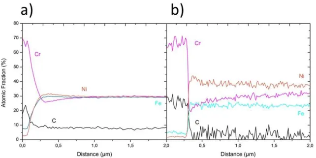
critical radius [3]. SEM observations clearly show that they do not nucleate at primary carbide / austenitic matrix interfaces and that a PFZ appears instead. This means that the solubility product is not reached in the PFZ. Since this solubility product is a function of the local composition, this might indicate that there is a composition gradient across primary carbide / matrix interfaces. To measure the local composition of the matrix near primary carbides in the as-cast material, analytical STEM analyses using EDS have been carried out in both steels. As shown in Fig. 6, a significant Cr gradient appears at such interfaces with a significant Cr depletion in the matrix. This depletion is about 5 and 10at.% in steel 1 and steel 2, respectively, (from 30at.% down to 25at.% Cr in steel 1 (Fig. 6(a)) and from 32at.% down to 20at.%Cr in steel 2 (Fig. 6(b))). These Cr gradients in the matrix spread over about one and two micrometers in steel 1 and steel 2, respectively.
Figure 6: a) STEM-EDS line profile analysis measured perpendicular to the interface of a primary carbide
towards the matrix in steel 1 in the as-cast state. It clearly exhibits a Cr depletion and a Ni enrichment at the carbide interface. b) STEM-EDS line profile recorded in similar way in steel 2 in the as-cast state. A chemical gradient is also exhibited at the interface between primary carbides and the matrix. One should note that the carbon quantification is not accurate using EDS, especially because of contamination, however the level being relatively constant in the matrix, it does not affect the Cr gradients.
Then, if such experimental data give some qualitative explanation of the observed PFZ, it does explain why some secondary M23C6 carbides continuously grow further and further away from primary
10 affects the solubility product. Besides, the diffusivity of carbon at 750°C in the austenitic matrix is relatively high. The equivalent diffusion distance estimated as ≈ √6𝐷𝑐𝑡 where 𝐷𝑐 is the carbon
diffusion coefficient given in Table 2 and 𝑡 the time, is indeed about 1 mm in only 16 h. Then, it is hard to understand why M23C6 does not homogeneously nucleate in the austenitic matrix since the carbon
concentration should be quite homogenous in the austenite. Therefore, to account for these complex phenomena (initial composition gradient, local solubility product evolution and carbon flux), the coupled diffusion/precipitation model described below has been developed.
4. Modelling of the secondary precipitation of M23C6 carbides
Classical nucleation and growth theories have been extensively used to model precipitation in isothermal and/or non-isothermal condition for steels [32], aluminium alloys [33] and superalloys [34]. From the pioneering contribution of Böhm et al [35], H.P. Van Landeghem [37] modelled the precipitation of CrN in an evolving N chemical gradient and Rougier et al [36] reported precipitation of ’ precipitates in a Ni-based superalloy. However, modelling precipitation kinetics in a concentration gradient has been seldom reported in the literature (see the recent contribution of [36]).
4.1 Fundamental basis of the modelling approach
The purpose is here to model the precipitation of the secondary carbides, supposedly driven by the carbon release from the primary M7C3 to M23C6 transformation, and within an initial chromium
gradient resulting from the precipitation of former M7C3. Therefore, a model coupling precipitation
and one-dimensional diffusion is designed.
The model developed for the present study is based on the software PreciSo developed by Perez et al., which is described in [27]. PreciSo uses classical nucleation theory, growth and coarsening in order to predict the size distribution of precipitates in multicomponent systems. For the sake of simplicity, complex M23C6 carbides are assumed to be spherical with Cr23C6 chemistry. The description for a
multi-component system can be found in reference [28]. At each time step of the simulation, when nucleation occurs, a new precipitate class is created. Its radius corresponds to the critical radius 𝑅𝑘𝐵𝑇
∗ calculated as follow: 𝑅𝑘∗𝐵𝑇 = 𝑅∗+ 1 2√ 𝑘𝐵𝑇 𝜋𝛾 (1)
11 where 𝑘𝐵 is the Boltzmann constant, is the precipitate/matrix interfacial energy. 𝑅∗ is the classical
critical radius above which nuclei are stable. It is the solution of dG(R*)/dR = 0, where the energy
change G(R) is given by:
∆𝐺(𝑅) =43𝜋𝑅3∆𝑔 + 4𝜋𝑅2𝛾 (2)
where g is the driving force for precipitation. The number of precipitates in the newly created class
is determined by the nucleation rate:
𝑑𝑁 𝑑𝑡 = 𝑁0𝛽 ∗𝑍exp [−∆𝐺(𝑅∗) 𝑘𝐵𝑇 ] [1 − exp (− 𝑡 𝜏)] (3)
where N0 is the number of nucleation sites per unit volume, * is the condensation rate of solute atoms
in a critical cluster and Z the Zeldovich factor.
At each time step, the radius of each class is updated. The new radius is calculated using a classical growth equation: 𝑑𝑅 𝑑𝑡 = 𝐷𝐶 𝑅 𝑋𝐶0−𝑋𝐶𝑖(𝑅) 𝛼𝑋𝐶𝑝−𝑋𝐶𝑖(𝑅)= 𝐷𝐶𝑟 𝑅 𝑋𝐶𝑟0 −𝑋𝐶𝑟𝑖 (𝑅) 𝛼𝑋𝐶𝑟𝑝−𝑋𝐶𝑟𝑖 (𝑅) (4)
where Dj are the diffusion coefficients (j stands for either Cr or C), 𝑋𝑗0 are the initial compositions of
the matrix (updated according to solute atoms diffusion, see next paragraph), 𝑋𝑗𝑝 are the compositions of the precipitate and 𝛼 = 𝑣𝑎𝑡𝑀⁄𝑣𝑎𝑡𝑃 is the matrix to precipitate atomic volume ratio.
Equation (4) implicitly takes into account the Gibbs-Thomson effect and therefore Ostwald Ripening since the composition of the matrix at the precipitate interface 𝑋𝑗𝑝(𝑅) depends on its radius. In a Cr23C6
phase, the composition is modified as follows:
𝑋𝐶𝑟𝑖 (𝑅)23𝑋𝐶𝑖(𝑅)6= 𝐾𝑆exp ( 58𝛾𝑣𝑎𝑡𝑃
𝑅𝑘𝐵𝑇) (5)
where KS is the solubility product of Cr23C6 in austenite.
In its most recent version called nodePreciso [29], the software is able to simulate precipitation in different “nodes” experiencing different thermal history. The precipitation software has been improved here to be able to model the precipitation within a chemical gradient of diffusing solute atoms. At the beginning of the simulation a mesh is defined. Each node i of the mesh has a given
12 volume Vi, a given solute content 𝑋
𝑗0𝑖 composition and is connected to neighboring nodes k via surfaces
Sik. Each time step of the simulation starts with a diffusion step during which a node can exchange
atoms with its neighbors. Fluxes of atoms through the defined surfaces are given by Fick’s law. At each time step, the solute contents 𝑋𝑗0𝑖 of each node i and for each atom species j are updated according
to: 𝑋𝑗0𝑖← 𝑋𝑗0𝑖+ 𝐷𝑗 𝑉𝑖∆𝑡 ∑ 𝑋𝑗𝑘−𝑋𝑗𝑖 |𝑥𝑘−𝑥𝑖| 𝑘(𝑛𝑒𝑖𝑔ℎ 𝑜𝑓 𝑖) 𝑆𝑖𝑘 (6)
where Vi is the volume of node i, t is the time step, xi,k is the position of node i, k and Sik is the surface
of ik interface. The summation is performed on all nodes k neighbors of node i.
This diffusion step is followed by performing the mass balance of all solute atoms in each node i according to:
𝑋𝑗𝑖 =
𝑋𝑗0𝑖−𝑋𝑗𝑝𝑖𝛼𝑓𝑖
1−𝛼𝑓𝑖 (6)
where 𝑓𝑖 is the precipitate volume fraction in node i and 𝛼 ∑ 𝑋𝑡 𝑗𝑖 is the net balance of solute atoms
that entered node i since the beginning of the simulation.
Finally, in each node, the nucleation and growth stages (eqs. (3), (4) and (5)) are calculated.
This new implementation will be used in order to simulate the precipitation of M23C6 secondary
carbides in a chromium composition gradient. The chosen thermodynamic and kinetic parameters for such simulations are reported in table 2.
The simulations focus on understanding how a composition gradient can influence nucleation, growth and coarsening. Therefore, the studied system is simplified with respect to the rather complex alloys studied experimentally and the following model was build:
i) the M23C6 phase is the only phase precipitating;
ii) each simulation consists of 21 nodes and the name of a node corresponds to its position along the x axis;
iii) node 0 represents the primary carbide that releases C from its transformation from M7C3 to M23C6
(the transformation itself is not modeled – precipitation is inhibited in this node);
iv) node 0 initially contains 18 wt.% Cr and 12 wt.% C (in order to take into account the fact that the transformation of the primary carbide is driven by Cr diffusion, the exchange surface between node 0 and node 1 has been reduced to 1.5 × 10⁻⁶ m² which corresponds to the ratio DCr / DC);
13 v) nodes 1 to 20 represent the surrounding austenitic matrix;
vi) each node is 1 m thick and is connected to its two neighbors by a unit surface of 1 m² (the problem is 1D);
vii) node 20 is 20 m away from the primary carbide interface and represents the center of a dendrite (the boundary condition applied at node 20 outer interface is that there is no flux);
viii) the initial Cr and C compositions of all nodes are fixed at the beginning of a simulation (initial C concentrations have been set to zero for all nodes, whereas various initial Cr gradients have been tested).
In short, this model represents a situation where C is released from the transformation of M7C3 into
M23C6, within a pre-existing Cr gradient. In this paper we will present three different cases: (i) no Cr
gradient; (ii) sharp Cr gradient; (iii) smooth Cr gradient.
4.2 Modelling results
Fig. 7 shows the evolution of the precipitate volume fraction and the Cr content in nodes 1 to 20 in the case of the smooth composition gradient (it corresponds to gradient 3 in figure 9). The initial Cr content can be seen at the origin of the diagram. Shortly after 2000 s, a small amount of M23C6 precipitates
starts to appear in nodes 9-20 quickly followed by nodes 8 and 7, and later on by nodes 6, 5 and 4. At the beginning of the simulation, the volume fraction of precipitates is higher in nodes further away from the primary carbide. After 5×10⁴ seconds though, nodes 7 and 8 become the more populated
14 Figure 7: Result of the modeling for a steel having a Cr content representative of steel 2 and exhibiting
chemical gradients across the interface between primary carbides and matrix. The volume fraction of precipitates (a) and the Cr content of the matrix (b) are plotted as a function of time in nodes 1 to 20.
Even if it seems surprising at first, the evolution of the volume fraction can be understood as follows. First, it is important to consider all parameters of the simulation: not only the volume fraction, but also the size distribution of the precipitates, their number density and the matrix composition. Since it is hard to follow all these parameters at once, typical simulated volumes have been represented in Fig. 8. These volumes have been generated by taking into account the aforementioned parameters. A cross section has been randomly cut through these volumes in order to provide a view of the microstructure that could be compared qualitatively with SEM observations.
15 Figure 8 : Visualization of the secondary carbide distribution at 750°C after 104 s (a), 105s (b) and 106s
(c). Both the precipitate free zone and the evolution of the size distribution as a function of time is clearly exhibited. Images were produced on the basis of the modelling results with a random distribution of carbides in each node.
Thanks to this representation, the precipitation sequence becomes clear. In the first steps of the simulation, the Cr content is highest in nodes 9-20. Since carbon diffuses much faster than chromium, all nodes see their C content increasing before nucleation even starts. Carbon flows out from the primary carbide (node 0) and meets nodes in which the Cr content is low. In these nodes, the Cr content is not high enough to reach the solubility limit for nucleation. Hence, nodes 1 to 3 correspond to the experimentally observed PFZ. In the following nodes (4 to 20), where the product [Cr]23[C]6 is high
enough, nucleation starts. Nodes 9-20 contain a lot of small precipitates. Nodes 4-8 contain much less precipitates, but these precipitates are larger. During the following time steps, these larger precipitates coarsen faster at the expense of the other ones due to the Gibbs-Thomson effect. With time, the difference between the large precipitates and the smaller distant ones is amplified. This explains the observation of a HPZ and the presence of small secondary carbides far from the transforming M7C3
carbides as can be seen in Figure 2. Even if the Cr content increases through time in nodes 1-3, the conditions for nucleation in these nodes is never met.
These simulations reproduce features observed during SEM investigation qualitatively. The first nodes are precipitate-free. This PFZ is followed by a zone where the volume fraction of precipitates is the highest and contains large precipitates. The more distant nodes, corresponding to the center of a
16 dendrite, contain a lot of smaller precipitates. In addition, it helps understanding the reasons for such a peculiar distribution of precipitates and how exactly a composition gradient can influence precipitation. The results show how thermodynamic and kinetics considerations have to be taken into account in order to understand the precipitation sequence, and that the interplay between composition gradients, the solubility product and diffusion coefficients is the key controlling the whole phenomena.
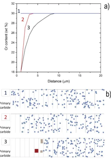
Figure 9 : Result of the modelling (750°C for 106 s) showing the influence of the chemical gradient at
the primary carbide / austenitic matrix interface. (a) Representation of the three different initial gradients (labelled 1: no gradient, 2: sharp gradient, 3: smooth gradient) used in the modelling, (b) corresponding visualization of the secondary carbide distribution showing a PFZ and a larger size distribution for the largest gradient.
In the literature, typical features such as the size distribution of precipitates, the PFZ, HPZ and LPZ vary a lot depending on aging conditions and alloy composition. This variability can be explained using our diffusion/precipitation model. For instance, simulations have been used in order to predict the precipitate distribution in the case of three different composition gradients. These gradients and the associated simulated volumes are represented in Fig. 9. In case 1 (no initial composition gradient), precipitation occurs everywhere. Even if the volume fraction is slightly higher in the nodes closer to the primary carbide / matrix interface (not shown here for the sake of simplicity), there is no striking
17 difference between node 1 and 20. This shows clearly that an initial composition gradient is the necessary condition leading to a PFZ, HPZ and LPZ. Moreover, by comparing cases 2 (sharp gradient) and 3 (smooth gradient) it clearly appears that the spatial extent of the gradient significantly affects the distribution of precipitates. In the case of a sharper gradient, the size of the PFZ is reduced. In addition, a smaller difference in precipitate size is observed between the nodes closer to the primary carbides and these ate the dendrite centre.
5. Conclusions
i) Heat resistant austenitic stainless steels exhibit secondary carbide precipitation as a result of the transformation of M7C3 primary carbides into M23C6 leading to some carbon release into the austenitic
matrix.
ii) Secondary M23C6 carbides start nucleating at a short distance of primary carbides, leaving a PFZ of
one micrometer or more.
iii) Nanoscaled secondary M23C6 carbides nucleate in the whole austenitic matrix (excepted in the PFZ),
but those near the carbon source (primary carbides) grow quickly and are the only ones visible by SEM for the early stage of aging (HPZ).
iv) In as-cast alloys, some chemical gradients exist within the structure, and especially a Cr depletion in the vicinity of M7C3 primary carbides has been observed.
v) The Cr gradients near the carbon source for secondary precipitation affect the local driving force for nucleation and give rise to a PFZ. This has been confirmed using coupled diffusion/precipitation simulations. Theses simulations take into account the flux of solutes with large difference in diffusion coefficients, the initial composition gradients in the matrix and the chemical driving force for nucleation and growth of M23C6 carbides.
vi) The simulations also predict that the extent and the amplitude of the Cr depletion zone affect the final spatial distribution of secondary carbides. This might explain the tremendous variations of the PFZ, and HPZ reported in the literature for commercial heat resistant steels.
vii) The secondary precipitation of M23C6 carbides can also be affected by crystalline defects like
dislocations or the strain field near MC carbides. Such features were beyond the scope of the present work but should be addressed in the future to capture the whole mechanisms.
Acknowledgements
This work has been funded by the Agence National de la Recherche (ANR), project IPERS, grant number LAB COM - 15 LCV4 0003. The authors are indebted to D. Embury for the fruitful discussions we have
18 had on the present results. The authors would like also to thank Charly Mougel for his contribution to the preliminary work carried out in this project.
References
[1] F. Abe, T.-U. Kern, R. Viswanathan, Creep-Resistant Steels - 1st Edition, Woodhead Publishing, 2008.
[2] M. Garbiak, W. Jasiński, B. Piekarski: Arch. Foundry Eng, 2011, vol. 11, pp. 47-52. [3] T. Sourmail: Mater. Sci. Technol, 2001, vol. 17, pp. 1–14.
[4] T. Sourmail, Simultaneous Precipitation Reactions in Creep-Resistant Austenitic Stainless Steels, PhD Thesis, 2002.
[5] L.H. de Almeida, A.F. Ribeiro, I. Le May: Mater. Charact, 2002, vol. 49, pp. 219–229. [6] A. Inoue, T. Masumoto: Metall. Trans. A, 1980, vol. 11, pp. 739–747.
[7] M.H. Lewis, B. Hattersley: Acta Metall, 1965, vol. 13, pp. 1159–1168.
[8] P.R. Landon, R.D. Caligiuri, P.S. Duletsky: Metall. Trans. A, 1983, vol. 14, pp. 1395–1408.
[9] R. Voicu, J. Lacaze, E. Andrieu, D. Poquillon, J. Furtado: Mater. Sci. Eng. A, 2009, vol. 510, pp. 185–189.
[10] B. Peng, H. Zhang, J. Hong, J. Gao, H. Zhang, Q. Wang, J. Li: Mater. Sci. Eng. A, 2011, vol. 528, pp. 3625–3629.
[11] L. Zheng, X. Hu, X. Kang, D. Li: Material and Design, 2015, vol. 78, pp. 42–50.
[12] Z. Zhang, Z. Hu, H. Tu, S. Schmauder, G. Wu: Mater. Sci. Eng. A, 2017, vol. 681, pp. 74–84. [13] A. Wiengmoon, T. Chairuangsri, J.T.H. Pearce: ISIJ International, 2004, vol. 44, pp. 396–403. [14] A. Wiengmoon, T. Chairuangsri, A. Brown, R. Brydson, D.V. Edmonds, J.T.H. Pearce: Acta Mater,
2005, vol. 53, pp. 4143–4154.
[15] A. Wiengmoon, T. Chairuangsri, N. Poolthong, J.T.H. Pearce: Mater. Sci. Eng. A, 2008, vol. 480, pp. 333–341.
[16] J. Wang, C. Li, H. Liu, H. Yang, B. Shen, S. Gao, S. Huang: Mater. Charact, 2006, vol. 56, pp. 73– 78.
[17] A.K. Sinha, J.J. Moore: Metallography, 1986, vol. 19, pp. 87–98.
[18] X.Z. Qin, J.T. Guo, C. Yuan, C.L. Chen, J.S. Hou, H.Q. Ye: Mater. Sci. Eng. A, 2008, vol. 485, pp. 74– 79.
[19] F.R. Beckitt, B.R. Clark: Acta Metall, 1967, vol. 15, pp. 113–129.
[20] G.D. Barbabela, L.H. de Almeida, T.L. da Silveira, I. Le May: Mater. Charact, 1991, vol. 26, pp. 1– 7.
[21] G.D. de Almeida Soares, L.H. de Almeida, T.L. da Silveira, I. Le May: Mater. Charact, 1992, vol. 29, pp. 387–396.
19 [22] H. Wen-Tai, R.W.K. Honeycombe: Mater. Sci. Technol, 1985, vol. 1, pp. 385–389.
[23] W.H. Jiang, X.D. Yao, H.R. Guan, Z.Q. Hu, W.H. Jiang: Metall. Mater. Trans. A, 1999, vol. 30, pp. 513–520.
[24] J. Rodrı ́guez, S. Haro, A. Velasco, R. Colás: Mater. Charact, 2000, vol. 45, pp. 25–32. [25] J. Liu, D. Jiao, C. Luo : Mater. Sci. Eng. A, 2010, vol. 527, pp. 2772–2779.
[26] K. Kaneko, T. Fukunaga, K. Yamada, N. Nakada, M. Kikuchi, Z. Saghi, J.S. Barnard, P.A. Midgley:
Scripta Mater, 2011, vol. 65, pp. 509–512.
[27] M. Perez, M. Dumont, D. Acevedo-Reyes: Acta Mater, 2008, vol. 56, pp 2119–2132.
[28] M. Perez, E. Courtois, D. Acevedo, T. Epicier, P. Maugis: Philos. Mag. Lett, 2007, vol. 87, pp. 645– 656.
[29] D. Bardel, M. Fontaine, T. Chaise, M. Perez, D. Nelias, F. Bourlier, J. Garnier: Acta Mater, 2016, vol. 117, pp. 81–90.
[30] J. Meija, T.B. Coplen, M. Berglund, W.A. Brand, B.P. De, M. Gröning, N.E. Holden, J. Irrgeher, R.D. Loss, T. Walczyk, T. Prohaska: Pure Appl. Chem, 2016, vol. 88, pp. 265–291.
[31] G. Neumann, C. Tuijn, eds., SELF-DIFFUSION AND IMPURITY DIFFUSION IN PURE METALS: HANDBOOK OF EXPERIMENTAL DATA, in: Pergamon Mater. Ser., Pergamon, 2008: p. iii.
[32] P. Maugis and M. Gouné: Acta Materialia, 2005, vol. 53, pp. 3359-3367.
[33] T. Dorin, A. Deschamps, F. De Geuser, C. Sigli: Acta Materialia, 2014, vol. 75, pp. 134-146. [34] L. Rougier, A. Jacot, C.A. Gandin, P. Di Napoli, P.Y Théry, D. Ponsen, V. Jaquet: Acta Materialia,
2013, vol. 61, pp. 6396-6405.
[35] G. Böhm, M. Kahlweit, Acta Metall., 12 (1964), pp. 641-648
[36] H.P. Van Landeghem, M. Gouné, A. Redjaïmia, Nitride precipitation in compositionally heterogeneous alloys: Nucleation, growth and coarsening during nitriding, Journal of Crystal Growth, Vol. 341, 2012, pp. 53-60
20
Tables
Table 1: Nominal composition (wt.%) of the two steels investigated in the present work (Fe and other minor elements balance). Other minor elements are: Mn, Si, P, S, Ti, Zr, Pb, Sn, Cu and Mo, with concentrations very close in both alloys.
Steel 1 Steel 2 C 0.45 - 0.5 0.4 - 0.5 Ni 33.0 - 36.0 39.0 - 42.0 Cr 24.0 - 27.0 29.0 - 32.0 Ta - 0.0 – 2.0 Al - 0.0 - 2.2 Nb 0.5 - 1.0 0.0 – 0.2
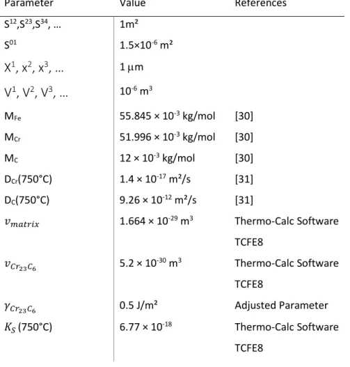
Table 2: Thermodynamic and kinetic parameters used for modeling of the precipitation with nodePreciSo
Parameter Value References
S12,S23,S34, … 1m² S01 1.5×10-6 m²
X
1, x
2, x
3, …
1 mV
1, V
2, V
3, …
10-6 m3 MFe 55.845 × 10⁻³ kg/mol [30] MCr 51.996 × 10⁻³ kg/mol [30] MC 12 × 10-3 kg/mol [30] DCr(750°C) 1.4 × 10⁻¹⁷ m²/s [31] DC(750°C) 9.26 × 10⁻¹² m²/s [31] 𝑣𝑚𝑎𝑡𝑟𝑖𝑥 1.664 × 10⁻²⁹ m3 Thermo-Calc Software TCFE8 𝑣𝐶𝑟23𝐶6 5.2 × 10⁻³⁰ m3 Thermo-Calc Software TCFE8 𝛾𝐶𝑟23𝐶6 0.5 J/m² Adjusted Parameter 𝐾𝑆(750°C) 6.77 × 10⁻¹⁸ Thermo-Calc Software TCFE821
Figure captions
Figure 1: Thermocalc simulation of equilibrium molar fractions of phases in steel 1 (a) and steel 2 (b)
as a function of temperature. M7C3 corresponds to the Cr-rich primary carbides. M23C6 corresponds to
the Cr-rich secondary carbides. NbC corresponds to the Nb-rich primary carbides. corresponds to a Fe- and Cr-rich intermetallic phase. G corresponds to the G-phase, an intermetallic silicide.
Figure 2: SEM images (secondary electron detector) showing the microstructure of steel 1 in the as cast
state (a) and after aging at 750°C during 16 h (b), 64h ((c) and (e)) and 112h (d). Precipitation of M23C6
secondary carbides in the vicinity of primary carbides is clearly exhibited for the early stage of aging, and it progressively extends in the matrix. The higher magnification image recorded in the austenitic matrix (e) reveals smaller secondary carbides and show some of them nucleated along a linear defects (supposedly a dislocation). For images a) and b) the samples were etched using A2 solution from Struers to image brightly the matrix and for images c), d) and e) the samples were etched using oxalic acid solution to image brightly the carbides). In Fig.2(a) the inset is a SAED pattern collected on a primary carbide and that demonstrates that these carbides exhibit a Cr7C3 structure.
Figure 3: TEM images (Bright field, High resolution and SAED pattern in (001) zone axis) showing
secondary M23C6 carbides that have nucleated and grown during aging at 750°C during 112h in the
austenitic matrix of steel 1 with a cube on cube orientation relationship.
Figure 4: SEM images (secondary electron detector) showing the microstructure of steel 2 (etched using
oxalic acid solution to image brightly carbides) after aging at 750°C during 16 h (a), 64h (b) and 112h (c). Precipitation of M23C6 secondary carbides in the vicinity of primary carbides is clearly exhibited for
the early stage of aging, and it progressively extends in the matrix.
Figure 5: Mean thickness of the precipitate free zone (PFZ) around primary carbides and mean distance
() of the observable secondary precipitation extension toward the austenitic matrix as a function of aging time at 750°C for steel 1 and steel 2 (measured from SEM images).
22 Figure 6: a) STEM-EDS line profile analysis computed perpendicular to the interface of a primary carbide
towards the matrix in steel 1 in the as cast state. It clearly exhibits a Cr depletion and a Ni enrichment at the carbide interface. b) STEM-EDS line profile recorded a similar way in steel 2 in the as-cast state. A chemical gradient is also exhibited at the interface between primary carbides and the matrix. One should note that the carbon quantification is not quantitative using EDS, especially because of contamination, however the level being relatively constant in the matrix, it does not affect the Cr gradients.
Figure 7: Result of the modeling for a steel having a Cr content representative of steel 2 and exhibiting
chemical gradients across the interface between primary carbides and matrix. The volume fraction of precipitates (a) and the Cr content of the matrix (b) is plotted as a function of time in nodes 1 to 20.
Figure 8: Visualization of the secondary carbide distribution at 750°C after 104 s (a), 105 s (b) and 106 s
(c). Both the precipitate free zone and the evolution of the size distribution as a function of time is clearly exhibited. Images were produced on the basis of the modelling results with a random distribution of carbides in each node.
Figure 9: Result of the modelling (750°C for 106 s) showing the influence of the chemical gradient at the
primary carbide / austenitic matrix interface. (a) Representation of the three different initial gradients (labelled 1: no gradient, 2: sharp gradient, 3: smooth gradient) used in the modelling, (b) corresponding visualization of the secondary carbide distribution showing a precipitate free zone and a larger size distribution for the largest gradient.