HAL Id: hal-00429227
https://hal.archives-ouvertes.fr/hal-00429227
Submitted on 2 Nov 2009HAL is a multi-disciplinary open access archive for the deposit and dissemination of sci-entific research documents, whether they are pub-lished or not. The documents may come from teaching and research institutions in France or abroad, or from public or private research centers.
L’archive ouverte pluridisciplinaire HAL, est destinée au dépôt et à la diffusion de documents scientifiques de niveau recherche, publiés ou non, émanant des établissements d’enseignement et de recherche français ou étrangers, des laboratoires publics ou privés.
Elimination of systematic errors in two-mode laser
telemetry
Clément Courde, Michel Lintz, Alain Brillet
To cite this version:
Clément Courde, Michel Lintz, Alain Brillet. Elimination of systematic errors in two-mode laser telemetry. Measurement Science and Technology, IOP Publishing, 2009, 20, pp.127002. �10.1088/0957-0233/20/12/127002�. �hal-00429227�
This is an author-created, un-copyedited version of an article accepted for publication in Measurement Science and Technology. IOP Publishing Ltd is not responsible for any errors or omissions in this version of the manuscript or any version derived from it. The definitive publisher authenticated version is available online at http://stacks.iop.org/0957-0233/20/127002
Elimination of systematic errors in two-mode laser telemetry
C Courde, M Lintz and A BrilletARTEMIS, Université de Nice Sophia-Antipolis, CNRS, Observatoire de la Côte d'Azur; Boulevard de l'Observatoire, 06304 Nice cedex 04, France.
Abstract
We present a simple two-mode telemetry procedure which eliminates cyclic errors, to allow accurate absolute distance measurements. We show that phase drifts and cyclic errors are suppressed using a fast polarization switch that exchanges the roles of the reference and measurement paths. Preliminary measurements obtained using this novel design show a measurement stability better than 1 micron. Sources of residual noise and systematic errors are identified, and we expect that an improved but still simple version of the apparatus will allow accuracies in the nanometre range for absolute
measurements of kilometre-scale distances.
Keywords: electronic distance measurement, metrology, cyclic error, polarization switching, phase lock loop
1. Introduction
The demand for accuracy in the measurement of long distances has increased with formation flight projects such as geodesy space missions, or space borne synthetic aperture telescopes. Large instruments such as high energy accelerators and colliders, dealing with micron or sub-micron sized particle beams, also require high accuracy ranging and monitoring of the stability of the underlying bedrock.
Early laser range meters [1, 2] used the simple set-up of an amplitude modulated laser beam, and exploited the phase difference between the reference and measurement paths. However, electronic phase drifts and cyclic errors are unavoidable at some level whenever a phase shift measurement is made so, while this method is simple and robust, it is not used in present day high accuracy range meters. Different strategies have been explored. For instance, "multi-wavelength" interferometry [3] has introduced the notion of a "synthetic wavelength" much longer than the optical wavelength. More recently, the advent of stabilized frequency combs available from mode-locked short pulse lasers has triggered new ideas. Joo et al. [4] exploit both synthetic wavelength and spectrally resolved interferometry on the same frequency comb. The suggestion by Ye [5] to combine time-of-flight and
interference measurements on phase-stabilized mode-locked lasers has triggered work by Cui et al. [6], and Coddington et al [7]. Salvadé et al. [8] have brought multi-wavelength interferometry to an accuracy of 8 nm. These advances, however, are obtained at the expense of sophisticated set-ups, that might require significant engineering to be space qualified.
This paper describes how we have implemented the modulated beam method in a way that eliminates drifts and cyclic errors. A polarization switch allows the roles of the reference and measurement paths to be exchanged, which provides an accurate zero for the phase comparison. The phase difference is then locked to zero by controlling the modulation frequency. The range information is obtained by a frequency measurement, which can be performed with high accuracy. The present stability of the measurement is in the 0.4 to 1.0 µm range. Sources of noise and systematic errors are identified and perspectives are finally given for improvements down to the nanometre level using this method.
2. Implementation of the measurement
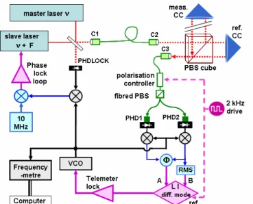
We phase-lock two single-frequency Nd:YAG 1.06µm lasers with a frequency offset F≈13 GHz. The collimated beam with intensity modulated at frequency F is sent to a polarizing beam splitter (PBS)
cube (see figure 1). The polarization is chosen so as to obtain two beams of equal intensity that travel, respectively, along a (short) reference path, and a (longer) measurement path. Once reflected from their corner cubes the reference and measurement beams are superimposed on the PBS and sent, respectively, to photodiode 1 (PHD1) and photodiode 2 (PHD2) using a fibred PBS.
Ideally, the phase difference of the PHD1 and 2 signals is locked to zero by control of the beat frequency F . This implies that the length difference ∆L ≡Lmeas −Lref
is an integer multiple of the synthetic wavelength: Λ
=
∆L K ≡Kc/F where the integer K is unknown, at the start of the measurements. The frequency F' of the next zero, corresponding to K +1 synthetic wavelengths, leads to unambiguous determination of ∆L
since [2] K =F/(F'−F). Then, by monitoring the frequency, one can continuously measure the distance.
Figure 1. Detailed implementation of the telemeter. Red lines: laser beams; green: optical fibres; black: HF (13.6 GHz) signal; blue: RF (10 MHz); purple: DC(<100kHz) signals; C1, C2, C3: fibred collimators; Ф: XOR phase meter; CC: hollow corner cube; RMS: RMS-to-DC converter.
Any shift in the phase difference signal (arising in the electronic or optical channels following the fibred PBS) would result in a systematic deviation of the length measurement. For instance, cross-talk from PHDLOCK to PHD1 or PHD2 gives rise to a cyclic error if it affects the latter photodiodes differently. To prevent these shifts from affecting the measurement, a polarization controller switches alternately the reference and measurement beams between PHD1 and PHD2, at about 2 kHz. A lock-in (LI) detector measures the part of the phase signal which reverses accordingly. We maintain the output of the LI detector at zero by applying a
feed-back to the voltage controlled oscillator (VCO). Constant shifts or aging give no contribution to the LI output. In particular, provided the reference and measurement signals have the same amplitude, the cyclic error will not affect the LI output, since it has the same value for both positions of the switch. This makes unnecessary to compensate shifts or cyclic errors. The polarization switch uses a Polarite II General Photonics polarization controller, based on piezo actuators squeezing a single mode optical fibre. This kind of controller shows a rather poor long-term stability that affects the quality of the polarization addressing (see below).
To analyse the phase meter output ("A" in figure 1) we use a Stanford Research Systems SR830 lock-in amplifier in differential mode. To the second input we apply a signal proportional to the amplitude of the RF signal of PHD2 ("B" in figure 1). This is due to the fact that amplitude-to-phase couplings affect the measurement, and have to be subtracted, as explained below.
3. Analysis of the measurement errors
3.1. Amplitude to phase coupling due to phase meter Our phase meter (based on an XOR logic circuit) has an amplitude-to-phase coupling that gives a 3x10⁻³ radian (equivalent to ≈ 5 µm) shift of the output for a 10% amplitude imbalance between the two signals. Even if the link budget is the same on the measurement and reference paths, an amplitude imbalance can arise when imperfect polarization addressing causes optical interference. Because of amplitude to phase coupling, any intensity change that reverses with the switch position gives rise to a systematic shift of the LI output.
Figure 2. Stability of the corrected telemeter signal. a: phasemeter output A demodulated by a first LI detector; b: RMS signal B demodulated by a second LI detector. The drifts are due to the long term instability of the polarization controller. The curve a+b shows that the two drifts cancel.
As shown in figure 2, the variations of the phase meter output appear largely correlated with the RMS amplitude
of the signal of one of the two photodiodes. The a+b corrected signal displays:
i): stability at the ≤ 2 µm level over long periods. These data are specifically recorded with short, symmetric arms so as to prevent thermal expansion from affecting the measurements.
ii): residual noise of < 3 µm peak to peak in the 1s to 10s period range.
All data presented below are obtained using the LI detector in differential mode for subtraction of amplitude effects.
3.2. Amplitude-to-phase coupling due to cross-talk In Section 2 we argue that at zero optical phase difference the cyclic error, unchanged in the switch, is eliminated. However, in case of a cross-talk, this argument fails if the signal amplitude changes when one switches from (+) to (-) : depending on the phase of the cross-talk, an amplitude to phase coupling can occur due to the combination of these two defects.
This contribution adds to that due to the XOR phase meter (Section 3.1). Indeed, when we adjust the coefficient for the subtraction of the amplitude-to-phase effects as shown in figure 2, we do cancel the resulting amplitude effect, regardless of its different origins. However, the coefficient, if optimal for a certain zero
K , may be non-optimal for another zero K'≠K , corresponding to a different frequency F'.
3.3. Signal noise due to optical back reflection from the photodiodes
PHD1 and 2 are fibred photodiodes at the FC/PC standard, and appear to give rise to a return loss of -15dB. Interferences between the reflected beams at PHD1 or 2 and at collimator C3 (see figure 1) have been identified as the source of the residual noise mentioned in 3.1-ii). Optical interference affects the phase of the detected beat note. Due to birefringence in the fibre, this phase shift couples to the polarization switching. The resulting contribution at LI output is affected by any change in the optical length between PHD1 (or 2) and collimator C3. This is obvious from the change in the noise spectrum when any of the optical fibres involved is heated, or when the frequency of the master laser is scanned over a few GHz in about 50s. This interference must be reduced for one to achieve precision at the nanometre level.
3.4 Phase noise due to the residual phase jitter of the beat note
When they are recombined on the PBS cube, the phase difference of the measurement and reference beams is not strictly 2 ∆π LF/c: the residual phase noise ϕ(t)of the phase lock of the two lasers adds a contribution
) ( ) /
(t L c ϕ t
ϕ −∆ − . This cannot be ignored, as the telemeter is designed to measure long distances. The standard deviation of the phase measurement at the lock-in detector output can be expressed as:
2 2 0 ) ( ). ( sin . ) ( . . 4 df S f π fT Gpb f σ
∫
ϕ ∞ =where T =∆L/c is the time of flight. Gpb( f) is a pass band filter transfer function to account for the action of the LI detector (24 dB/octave noise rejection and 10 ms integration time). The power spectral density of the single sideband phase noise of the beat note Sϕ( f) can be measured by a spectrum analyzer. For a 1 km distance (∆L=2km), the expected RMS noise is
5 10 8 .
2 − radians (≈ 100 nm) with the observed Sϕ( f) spectrum. This could be lowered considerably by the use of an improved phase lock loop.
As usual, the fundamental limits that apply to light detection are shot noise and thermal noise. For a detected photocurrent i = 1 mA, and a 50Ω load resistor at the temperature of 300 K, they each contribute to a noise power of 2eiR ≈4kBT ≈1.6⋅10−20 W/Hz, or a linear signal to noise ratio of
7 2 10 5 . 5 4 2 / ≈ + ⋅ ≈ T k eiR i R N S B Hz1/2 .
Allowing for a noise factor of 10 dB in the HF amplifier and demodulation system, we expect that light detection will limit the resolution to ≈ Λ ≈
N S/
3
1 nm/Hz1/2.
4. Consistency and stability of the measurements of an 8m path
The extraction of K shows no error, and the non-integer residues are much smaller than 1 (typical RMS value 0.06) when different zeroes are scanned: K , K +1,
2 +
K , etc. The different length measurements L(K), )
1 (K+
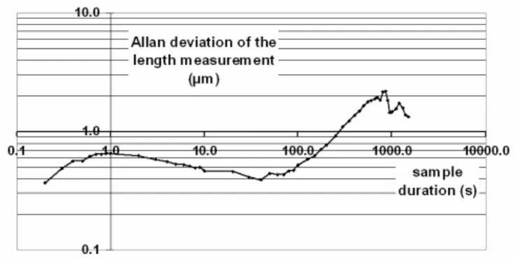
L , etc. differ by a few microns, as expected due to thermal changes of the optical table during the measurements. However the standard deviation of the measurement can vary by as much as a factor of 10 from one zero to the next. This is likely to originate in the observed cross-talk from PHDLOCK to the measurement photodiodes, as mentioned in § 3-2. On the Allan deviation data of figure 3, one can note a short term (0.1s - 10s) noise of 0.5 to 1µm RMS, which results from the noise mentioned in section 3.1.ii. The long term variations of the length measurement are likely to involve thermal changes of the optical table, and not drifts of the measuring system, which would be manifest as drifts on the corrected telemeter signal a+b in figure 2.
Figure 3. Allan deviation of the measurements of an
≈8m path implemented on the optical table. The room temperature is not stabilized.
5. Conclusions and perspectives
In this paper we have shown that cyclic errors and cable or electronic drifts can be efficiently suppressed in two-mode laser ranging, if the roles of the two photodiodes, with respect to the reference and measurement paths, are exchanged at a kHz rate. This approach is potentially capable of high accuracies, as the distance determination entirely relies on a frequency measurement, with no need to know, or even stabilize, the optical frequency of the master laser source.
Two main sources of systematic errors have been identified.
The amplitude-to-phase coupling problem can be improved using another kind of polarization controller, with better long term stability. But most importantly, residual HF signal amplitude imbalance should be locked to zero by control of the polarization of the beam entering the PBS cube. This seems necessary, since the reference/measurement beam intensity ratio will vary in a real long distance ranging experiment due to variations of the link budget. Finally, the HF isolation should be improved, since cross-talk is involved in amplitude-to-phase coupling.
The optical return from the photodiodes could be improved by about -20dB by using FC/APC -rather than FC/PC- fibred photodiodes. Inserting an optical isolator before each of the two photodiodes should provide another reduction, of more than 40dB, leading to a reduction of about 10 of the corresponding systematic 3 effect.
For these reasons we expect that this simple telemeter design will reach accuracies in the nanometre range and, due to the unsophisticated set-up, will comply to demands for space borne or on-board applications. Acknowledgments
This work is supported by CNES, Thales Alenia Space, and Région PACA.
References
[1] Bender P L 1967 Laser measurements of long distances Proc. IEEE 55 1039
[2] Rüeger J M 1990 Electronic distance measurement (Springer Verlag, Berlin).
[3] Dändliker R, Hug K, Politch J and Zimmermann E 1995 High-accuracy distance measurements with multiple-wavelength interferometry Opt. Eng. 34 2407 [4] Joo K N, Kim Y and Kim S-W 2008 Distance measurements by combined method based on a femtosecond pulse laser Opt. Express 16 19799
[5] Ye J 2004 Absolute measurement of a long, arbitrary distance to less than an optical fringe Opt. Lett. 29 1153
[6] Cui M, Schouten R N, Bhattacharya N, van den Berg S A 2008 Experimental demonstration of distance measurement with a femtosecond frequency comb laser J. Eur. Opt. Soc. 3 08003
[7] Coddington I, Swann W C, Nenadovic L and Newbury R N 2008 Rapid and precise absolute distance measurements at long range Nature. Photonics 3 351 [8] Salvadé Y, Schuhler N, Levêque S and Le Floch S 2008 High-accuracy absolute distance measurement using frequency comb referenced multiwavelength source Appl. Opt. 47 2715-20