HAL Id: hal-01410044
https://hal.archives-ouvertes.fr/hal-01410044
Submitted on 6 Dec 2016
HAL is a multi-disciplinary open access
archive for the deposit and dissemination of
sci-entific research documents, whether they are
pub-lished or not. The documents may come from
teaching and research institutions in France or
abroad, or from public or private research centers.
L’archive ouverte pluridisciplinaire HAL, est
destinée au dépôt et à la diffusion de documents
scientifiques de niveau recherche, publiés ou non,
émanant des établissements d’enseignement et de
recherche français ou étrangers, des laboratoires
publics ou privés.
Innovative linear pulsatile pump for heart assistance
circulatory
Jean-François Llibre, Nicolas Martinez, Pascal Leprince, Bertrand Nogarède
To cite this version:
Jean-François Llibre, Nicolas Martinez, Pascal Leprince, Bertrand Nogarède. Innovative linear
pul-satile pump for heart assistance circulatory. LDIA 2011 - 8th International Symposium on Linear
Drives for Industry Applications, Jul 2011, Eindhoven, Netherlands. pp.0. �hal-01410044�
O
pen
A
rchive
T
oulouse
A
rchive
O
uverte (
OATAO
)
OATAO is an open access repository that collects the work of Toulouse researchers and
makes it freely available over the web where possible.
This is an author-deposited version published in:
http://oatao.univ-toulouse.fr/
Eprints ID: 16671
To cite this version: Llibre, Jean-François and Martinez, Nicolas and Leprince,
Pascal and Nogarède, Bertrand Innovative linear pulsatile pump for heart
assistance circulatory. (2011) In: LDIA 2011 - 8th International Symposium on
Linear Drives for Industry Applications, 3 July 2011 - 6 July 2011 (Eindhoven,
The Netherlands, Europe)
Any correspondence concerning this service should be sent to the repository administrator:
Innovative linear pulsatile pump for heart assistance circulatory
Jean-François Llibre1,2, Nicolas Martinez3, Pascal Leprince4 and Bertrand Nogarede1,2
1
Université de Toulouse; INPT, UPS; ENSEEIHT, 2 rue Charles Camichel, BP 7122, F-31071 Toulouse cedex 7, France
²CNRS; LAPLACE; F-31071 Toulouse, France
3
Novatem SAS; ENSEEIHT, 27 rue d’Aubuisson F-31071 Toulouse cedex 7, France
4
Institut de cardiologie, Groupe Hospitalier Pitié-Salpêtrière, 47-83 Boulevard de l’hôpital, 75013 Paris, France
Email: [email protected] ABSTRACT
The present contribution deals with the
development of a magneto-active pump devoted to ventricular assist device. The actuator studied is a cylindrical linear switched reluctance motor equipped with a unidirectional mechanical valve inside the tubular mover in order to allow a pulsatile flow. On the bases of theoretical results, a demonstrator has been designed and built in the laboratory. Finite element analysis of this demonstrator has been performed and preliminary tests are detailed showing the flow and pressure characteristics.
1 INTRODUCTION
Heart failure is one of the most common diseases in developed countries. Because the number of donor heart is limited, patients suffering from end-stage heart failure require mechanical circulatory support as bridge to transplant, bridge to recovery or destination therapy. Most of the time, the mechanical circulatory support is a left ventricular assist device (VAD) or artificial heart pump developed to aid the failed left ventricle by supplying additional flow of blood to the body. In case of severe heart failure, a total artificial heart (TAH) completely replaces the native heart and assumes the function of both ventricles [1].
At the beginning of cardiovascular surgery, the mechanical circulatory support which was a pneumatic pump mimics the heart functioning by providing a pulsatile flow of blood. However, the large and bulky sizes of these devices contribute to serious complications. In [2], a linear switched reluctance motor (LSRM) called linear pulse motor was studied and used in acute animal testing.
Actually, the last generation of mechanical circulatory support consists of miniature rotary pumps providing continuous flow. One can cite the Jarvik 2000, the MicroMed DeBakey and the Heart Mate II which are axial electromagnetic pump constituted of a motor and a turbine [3]. They allow increase of the autonomous of the patient and more acceptable way of life. The successful of these devices is limited by thromboembolic events and pump thrombosis. The implications of continuous flow conditions for long term durations remain unclear to the medical and scientific community [4].
For testing these VADs the use of mock circulatory systems is essential [5]. In-vivo tests on animals such as
calves, goats, sheep and pigs are also performed [6]. To prevent thrombosis, we propose to study a pulsatile flow pump for in-vivo tests on pig. The physiological needs are a pressure of 120 mmHg, a flow of 3 liters/min and a heart rate of 120 bpm (beats per minute).
The actuator chosen is a cylindrical linear reluctance variable motor equipped with a mechanical aortic valve inside the tubular mover allowing pulsatile flow of the blood. After the analytical and simulation studies, the demonstrator and preliminary tests are shown. The present project results from the collaboration between researchers in cardiac surgery (AP-HP Pitié Salpêtrière) and researchers in electrodynamics (GREM3 Laplace).
2 THE PROPOSED CONCEPT
2.1 Presentation of the concept
The proposed structure for this application is a cylindrical LSRM where the mover part has no windings like [7, 8]. It consists of a moving ferromagnetic hollow cylinder with transverse slots and an outer cylindrical stator containing a number of identical phase sets. Each set consists of a magnetic core, formed of two discs and a ring, and an enclosed solenoidal winding. In the same manner a six phase cylindrical LSRM has been developed for heart assistance circulatory [9].
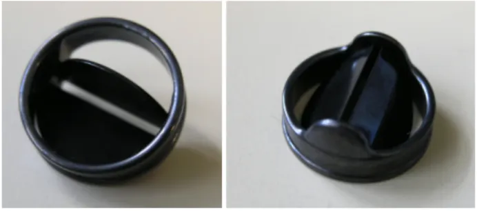
The actuator studied, called Pulsamag V3 is the third version of a concept presented in [10]. A mechanical unidirectional valve is fixed inside the cylindrical mover. This aortic valve shown in Fig. 1 made by St. Jude Medical, as a diameter of 25 mm and allows the blood circulation.
Figure 1: St Jude Medical mechanical valve.
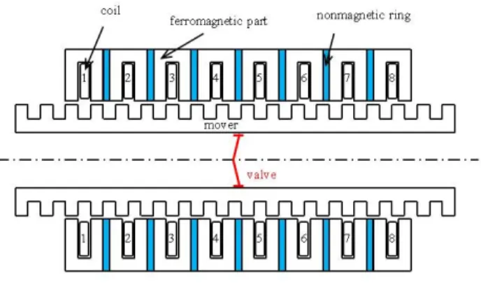
As shown in Fig. 2, the cylindrical LSRM studied is composed of a stator with 4 phases and 8 coils (2 coils
per phase) and a tubular mover. Each set of the stator is separated from its neighbor by a nonmagnetic ring. The phase number 1 is composed of the coils number 1 and 5. The other coils and phases are numbered in the same way.
Figure 2: Basic structure of Pulsamag V3.
The coils are sequentially excited in order to create a magnetic field moving from one side to the other end. Then the cylindrical magnetic mover performs an oscillatory movement. The closed aortic valve pushes the fluid in the flow direction, and when the cylinder comes back to its initial position the valve is opened so as to not interact with the fluid. Figure 3 shows the design of Pulsamag V3 used in the numerical studies.
Figure 3: Pulsamag V3.
In this low speed application, because of low eddy current losses, the magnetic core does not have to be made of laminated steel. Moreover, due to the cylindrical shape, the normal forces are neutralized. The other advantages of this kind of actuator are its reliability, its simplicity of implementation, its ability to generate a linear motion directly (without mechanical processing)… There may be mentioned for the disadvantages, a low efficiency due to joule losses that increase in the same way that the desired mechanical efforts and the difficulty of guiding the mover part to ensure a constant air gap. The latter is usually small to ensure good performances. 2.2 Kinetic characteristics
The stroke of the St. Jude Medical valve and the mover is done by (1). f S Q L . 6 103 = (1)
With: L the stroke of the mover in mm, Q the desired flow in liters/min, S the section of the valve in cm² and f the desired frequency in Hz.
The thrust of the mover is done by (2).
10 .S P
F= (2)
With: F the thrust in N and P the pressure in kPa.
The physiological needs for VAD are a flow of 3 liters/min and a pressure of 120 mmHg (16 kPa) under a frequency of 2 Hz. So with a 25 mm diameter valve, the stroke is L = 51 mm and the thrust is F ≅ 8 N.
In order to obtain the above values, we present in the next section an analytical model of the actuator and the elements to perform a dimensioning.
3 DESIGN AND SIMULATION
3.1 Analytical model of the phase set
From the actuator presented in Fig. 2, we can notice that each phase set forms an independent magnetic circuit thanks to the nonmagnetic ring. When a coil is supplied, the teeth of the corresponding coil and the teeth of the mover tend to align in order to maximize the magnetic flux. The phase set or basic pattern of the actuator is presented in Fig. 4.
Figure 4: Basic pattern.
The radial dimensions are: hst stator tooth length, hmt
mover tooth length, esy stator yoke thickness, emy mover
yoke thickness, Rv valve radius, Rg air gap radius and
Rext external radius. The axial dimensions are: a tooth
width and b slot width.
In order to ensure a smooth functioning, we have chosen the tooth pitch of the stator λλλλs and the tooth pitch
of the mover λλλλm equal:
b a m s =λλλλ =λλλλ= + λ λλ λ . (3)
We have chosen the tooth width and the slot width equal too:
b
By assuming a linear model of the basic pattern, the analytical expression of the traction or propulsion force can be calculated using the principle of conversion of energy as in [11, 12]. The lateral force given by (5) is function of the air gap flux density Bg and the air gap
exchange area. This latter is function of the air gap length g and the air gap radius Rg.
g g y g R B F ππππ µ µ µ µ 2 2 2 0 2 ⋅ ⋅ = (5)
By neglecting the magnetic potential in the iron, the magnetomotive force (mmf) Ni can be expressed by (6).
0 2 µ µ µ µ g B g Ni= (6)
Then the analytical expression of the lateral force of the basic pattern in terms of the mmf is given by (7). This expression is identical to that given in [8].
( )
2 02g Ni
R
Fy = µµµµ ππππ g ⋅ (7)
3.2 Dimensioning of the actuator
From (7), one can notice that the mean thrust is high when the air gap length g is small and the air gap radius Rg is high. Moreover, the increasing of the mmf leads to
an increasing of the thrust but also an increasing in the same way of the copper loss.
One dimensioning factor for LSRM is the maximization of the mean static force per copper loss. In [8], this optimization gives the result mentioned in (8).
(
)
(
ext sy)
g R e
R ≅ 2−1⋅ − (8)
If we neglect in (8) the stator yoke thickness esy
compared to the external radius Rext, the radius air gap Rg
is equal to 0.4Rext. In the same time, the stator tooth
length hst is equal to 1.4Rg.
The stroke of the actuator is another major consideration for the dimensioning. It depends on: the tooth pitch length λλ, the nonmagnetic ring thickness c, λλ the number of phases m and the number of coils per phase n. To increase the stroke for a given elementary pattern dimensions, we can increase the phase number m and/or the coil per phase number n. By supplying several coil in serial (n ≠ 1), both the stroke and the trust increase.
The total length of the stator LsT is given by (9).
(
a b) (
m n)
c nm
LsT = ⋅ ⋅ 2 + + ⋅ −1⋅ (9)
The total length of the mover LmT is dependant of the
desired stroke and is given by (10). sT
mT stroke L
L ≥ + (10)
The total expected thrust FyT is given by (11).
( )
2 0 2g Ni R n FyT = ⋅µµµµ ππππ g ⋅ (11)In Fig. 2, if we consider that the coil number one is energized, the position of the mover is at an equilibrium position corresponding to an aligned position of the teeth. Then the distance between the stator tooth of the next coil
(coil number two) and the closest mover tooth is done by (12) and called the mechanical step λλλλp.
c b m p = = − λ λλ λ λ λλ λ (12) 3.3 Prototype dimensions
The actuator presented in Fig. 2 and 3 has m = 4 phases and n = 2 coils per phase. The thickness of the nonmagnetic ring c is chosen equal to half the tooth width a. Then according to (3), (4) and (11), the expression of the mechanical step λλλλp becomes:
c a p = = = 2 4 λ λ λ λ λ λλ λ . (12)
Phase number 1 consists of coils 1 and 5 in series. The other phases are formed and numbered in the same way. When supplying the phases in order 1, 2, 3, and 4 by a four phase current system leads to a leftward shift whereas the reverse sequence 1, 4, 3 and 2 leads to a rightward shift.
Because the valve diameter is equal to 25 mm, the external radius Rext according to (8) will be larger than
31 mm. In order to limit the bulk of the actuator (external radius inferior to 30 mm) and the mass of the mover, the dimensions given in Table 1 have been chosen.
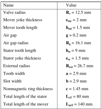
Table 1: Prototype dimensions.
Name Value
Valve radius Rv = 12.5 mm
Mover yoke thickness emy = 2 mm
Mover tooth length hmt = 1.5 mm
Air gap g = 0.2 mm
Air gap radius Rg = 16.1 mm
Stator tooth length hst = 9 mm
Stator yoke thickness esy = 1.5 mm
External radius Rext = 26.7 mm
Tooth width a = 2.9 mm
Slot width b = 2.9 mm
Nonmagnetic ring thickness c = 1.45 mm
Total length of the stator LsT = 80 mm
Total length of the mover LmT = 140 mm
For the application considered, the desired stroke and thrust are respectively 51 mm and 8 N. According to the dimensions above, the stroke is available. By using (11), in order to respect the specifications, the mmf Ni is equal to 158 At with a slot fill factor of 100% which is not realistic.
The slot area is equal to: 1 . 26 = ⋅ = st slot b h A mm². (13)
Because of the low value of Aslot, the number of turns
per slot N of the prototype is not very high: N = 155 with a turn diameter of 0.335 mm. So the coil area Acoil is
equal to 13.66 mm² and the slot fill factor kfill can be
expressed by (14). 523 . 0 = = slot coil fill A A k (14)
We can then give in (15) the expression of the mmf Ni in terms of the above areas expressed in mm² and the current density J expressed in A/mm².
J A k J A
Ni= coil⋅ = fill ⋅ slot ⋅ (15)
So for a current supply of i = 1 A corresponding to a mmf Ni = 155 At and a current density in the coil J = 11.3 A/mm², the analytical thrust using (11) is equal to 7.6 N.
4 TWO DIMENSIONS FEM ANALYSIS
4.1 One phase power supply sequence
A two dimensions finite element simulation of the whole actuator with ANSYS Multiphysics software has been carried out. The core magnetic material of the stator and the mover is made of XC-38 steel. The core material magnetization characteristic B(H) used in the numerical simulations is given in Fig. 5.
Figure 5: B-H characteristic of the iron magnetic circuit (XC-38 steel). Because the actuator geometry is axisymmetric, the structure that was simulated is half that shown in Fig. 2.
Figure 6 shows the magnetic flux density for phase number one supplied alone (coils 1 and 5) with the mmf Ni equals to 155 At. The position of the mover with regard of the stator teeth of coil number 1 fits with the maximal thrust position. We can notice on Fig. 6 that the magnetic material does not saturate. The magnetic flux density in the yoke is less than 1.5 T.
With the help of the software, we have calculated the forces exerted on the mover. The forces calculated according to the Maxwell tensor and virtual work techniques are called respectively Fmx and Fvw. Figure 7 shows for each position of the mover (0.1 mm step) efforts calculated when the four phases are excited one by one with a mmf Ni equals to 155 At.
Figure 6: Magnetic flux density: phase 1 supplied with Ni = 155 At. The position 100% of the mover corresponds to a shift of λλ. We called Fmx-Ph"i" et Fvw-Ph"i" the λλ forces calculated when phase number "i" is supplied.
Figure 7: Force vs mover position: one phase supplied at a time
Ni = 155 At.
To provide a continuous movement to the left (respectively right), we must supply the four phases successively in the order 1-2-3-4 (respectively 4-3-2-1). Figure 8 shows the power supply sequence that ensures a movement to the right.
Figure 8: Power supply sequence: one phase supplied at a time. Thus Fig. 9 represents the force developed by the mover for left and right movements.
0 0,5 1 1,5 2 2,5 0 5000 10000 15000 20000 25000 30000 35000 40000 Magnetic induction, B (T)
Magnetic field, H (A/m)
B (H) -8 -6 -4 -2 0 2 4 6 8 0 10 20 30 40 50 60 70 80 90 100 Force (N) Position (%) Force vs Position Fvw-Ph1 Fmx-Ph1 Fvw-Ph2 Fmx-Ph2 Fvw-Ph3 Fmx-Ph3 Fvw-Ph4 Fmx-Ph4
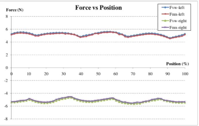
Figure 9: Force vs mover position with power supply sequence of Fig. 8 performed.
The maximum and average values of thrust obtained are respectively 5.6 N and 5.2 N. These values can be compared to the value obtained in Section 3.3 for a linear functioning which was 7.6 N.
4.2 Two phases power supply sequence
Because the thrust is not enough sufficient, we have decided to supply two phases at the same time. Figure 10 shows the magnetic flux density in the actuator for phases 1 (coils 1 and 5) and 4 (coils 4 and 8) supplied with the mmf Ni equals to 155 At. The position of the mover with regard of the stator teeth of phases 1 and 4 fits with the maximal thrust position.
Figure 10: Magnetic flux density: phase 1&4 supplied with Ni = 155 At.
We can see the in the mover yoke the beginning of magnetic saturation with a value of 1.7 T for the magnetic flux density. This value stills acceptable.
We have calculated like in the previous section forces with the Maxwell tensor and virtual work techniques for different positions of the mover. The phases are supplied in pairs (phases 1 and 2, phases 2 and 3, phases 3 and 4 and then phases 4 and 1) with a unidirectional power supply with a constant current i = I. The power supply sequence is given in Fig. 11.
Figure 11: Power supply sequence: two phases supplied at a time. Figure 12 shows the thrust when the previous power supply sequence is respected.
Figure 12: Force vs mover position with power supply sequence of Fig. 11 performed.
The maximum and average values of thrust are respectively 9.7 N and 8 N in both directions; the latter correspond to the desired value. This thrust is lower than the thrust obtained using (11) with n = 4 (four coils supplied) and Ni = 155 At: FyT = 15.3 N.
Indeed we can notice the nonlinearity of the functioning. Some leakage flux attracts the mover teeth in the opposite direction to the average effort thus reducing the overall effort. The model based on one stator set (cf. Fig 4) with the analytical expressions of the force given in (7) and (11) does not take into account the leakage flux.
5 TEST OF THE DEMONSTRATOR
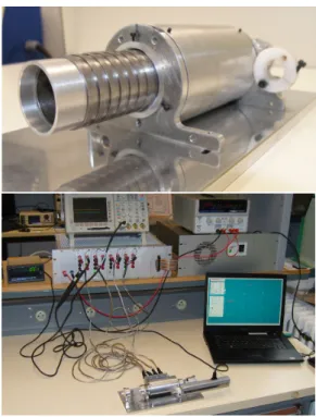
Figure 13 shows the picture of the prototype Pulsamag V3 with its support and supply and also the picture of the full test-bench: the prototype, the position sensor, the control module, the power supply and the control PC.
To control the actuator we use a dSPACE system. A position sensor Mitutoyo LGF-550L with a signal conditioner EH10P is used to find the precise position of the translator in order to supply the appropriate coils. The power electronics chosen to supply the prototype has
-8 -6 -4 -2 0 2 4 6 8 0 10 20 30 40 50 60 70 80 90 100 Force (N) Position (%)
Force vs Position Fvw-left Fmx-left Fvw-right Fmx-right -12 -10 -8 -6 -4 -2 0 2 4 6 8 10 12 0 10 20 30 40 50 60 70 80 90 100 Force (N) Position (%)
Force vs Position Fvw-left Fmx-left Fvw-right Fmx-right
been developed by the company NOVATEM SAS and consists of H bridges.
Figure 13: Pulsamag V3 prototype.
Preliminary tests have been done with water and a not optimized supply sequence as the one shown in Fig. 8. The pressure characteristic vs. flow at 1 Hz frequency (60 bpm) is done in Fig. 14. 0 10 20 30 40 50 60 70 0 0,2 0,4 0,6 0,8 1 1,2 1,4 1,6 P re ss u re (m m H g ) Flow (liters/min)
Figure 14: Pressure vs. Flow of PULSAMAG V3 at 1 Hz. Other supply sequences should be tested at different frequencies in order to obtain the desired pressure of 120 mmHg.
6 CONCLUSION
This paper presents a cylindrical linear switched reluctance motor providing pulsatile flow of blood to be used as a mechanical circulatory support. An analytical model of the actuator based on an elementary pattern and linear functioning has been presented. Thus the analytical expression of the mean static thrust of the whole actuator is given. A 2D FEM analysis has been performed taking account the nonlinearity of the magnetic material. The expected thrust can be reached with a power sequence
supply where two phases are excited at the same time. Preliminary tests of the demonstrator with a mechanical aortic valve allow us to think that the physiological needs can be reached. More tests have to be performed and particularly the measure of the losses and the efficiency. In the future, other structures of cylindrical linear motor with permanent magnets can be studied for providing a pulsatile flow of blood.
REFERENCES
[1] P.L. DiGiorgi, Y. Naka, M.C. Oz, “Left ventricular assist devices,” Contemporary Cardiology: Surgical management of congestive heart failure, Chapter 7, pp. 155--189, 2005.
[2] H. Yamada, M. Yamaguchi, H. Kobayashi,
Y. Matsuura, H. Takano, “Development and test of a linear motor-driven total artificial heart,” IEEE Engineering in medicine and biology magazine, vol. 14, Issue 1, pp. 84--90, 1995.
[3] A. Blitz, J.C. Fang, “Ventricular assist devices and total artificial hearts,” Contemporary Cardiology: Device therapy in heart failure, Chapter 13, pp. 339--371, 2009.
[4] G. S. Allen, K.D. Murray, D.B. Olsen, “The importance of pulsatile and non pulsatile flow in the design of blood pumps,” Artificial Organs, vol. 21, Issue 8, pp. 922--928, 1997.
[5] D. Timms, M. Hayne, K. McNeil, A. Galbraith, “A complete mock circulation loop for the evaluation of left, right, and biventricular assist devices,” Artificial Organs, vol. 29, Issue 7, pp. 564--572, 2005.
[6] H. Yamada, M. Yamaguchi, M. Karita, Y. Matssura, S. Fukunaga, “Acute animal experiment using a linear motor-driven total artificial heart,” IEEE Trans. J. Mag. in Japan, vol. 9, Issue 6, pp. 90--97, 1994. [7] J. Corda, E. Skopljak, “Linear switched reluctance
actuator,” 6th International Conference on Electrical Machines and Drives, pp. 535--539, 1993.
[8] L. El Amraoui, F. Gillon, S. Vivier, P. Brochet, M. Benrejeb, “Optimal design approach for linear tubular machines,” IEEE International Conference on Systems Man and Cybernetics, vol. 5, pp. 1--6, 2002. [9] H. Yamada, T. Hamajima, S. Xiang, N. Nishizawa,
“Six-phase linear pulse motor as linear oscillatory actuator,” IEEE Trans. Mag., vol. MAG-23, No. 5, pp. 2841--2843, 1987.
[10] N. Martinez, P. Leprince, B. Nogarede, “A novel concept of pulsatile magnetoactive pump for medical circulatory support,” Electrical Machines ICEM, pp. 1--6, 2008.
[11] B-S. Lee, H-K. Bae, P. Vijayraghavan, R. Krishnan “Design of a linear switched reluctance machine,” IEEE Transactions on Industrial Applications, vol. 36, No. 6, pp. 1571--1580, 2000.
[12] I-A. Viorel, K. Hameyer, L. Strete, “Transverse flux tubular switched reluctance motor,” 11th International Conference on Optimization of Electrical and Electronic Equipment, OPTIM'08, pp. 131–136, 2008.