HAL Id: hal-01793518
https://hal.archives-ouvertes.fr/hal-01793518
Submitted on 16 May 2018
HAL is a multi-disciplinary open access
archive for the deposit and dissemination of
sci-entific research documents, whether they are
pub-lished or not. The documents may come from
teaching and research institutions in France or
abroad, or from public or private research centers.
L’archive ouverte pluridisciplinaire HAL, est
destinée au dépôt et à la diffusion de documents
scientifiques de niveau recherche, publiés ou non,
émanant des établissements d’enseignement et de
recherche français ou étrangers, des laboratoires
publics ou privés.
Direct numerical simulation of nucleate boiling in
micro-layer regime
Annafederica Urbano, Sébastien Tanguy, Grégory Huber, Catherine Colin
To cite this version:
Annafederica Urbano, Sébastien Tanguy, Grégory Huber, Catherine Colin. Direct numerical
simu-lation of nucleate boiling in micro-layer regime. International Journal of Heat and Mass Transfer,
Elsevier, 2018, vol. 123, pp. 1128-1137. �10.1016/j.ijheatmasstransfer.2018.02.104�. �hal-01793518�
To cite this version
: Urbano, Annafederica and Tanguy, Sébastien and Huber,
Grégory and Colin, Catherine Direct numerical simulation of nucleate boiling
in micro-layer regime. (2018) International Journal of Heat and Mass Transfer,
vol. 123. pp. 1128-1137. ISSN 0017-9310
O
pen
A
rchive
T
OULOUSE
A
rchive
O
uverte (
OATAO
)
OATAO is an open access repository that collects the work of Toulouse researchers and
makes it freely available over the web where possible.
This is an author-deposited version published in :
http://oatao.univ-toulouse.fr/
Eprints ID : 19833
To link to this article
: DOI: 10.1016/j.ijheatmasstransfer.2018.02.104
URL :
http://dx.doi.org/10.1016/j.ijheatmasstransfer.2018.02.104
Any correspondence concerning this service should be sent to the repository
administrator:
[email protected]
Direct numerical simulation of nucleate boiling in micro-layer regime
A. Urbano
⇑, S. Tanguy, G. Huber, C. Colin
Institut de Mécanique des Fluides de Toulouse (IMFT), Université de Toulouse, CNRS, Toulouse, France
a b s t r a c t
The physical mechanisms associated with the evolution of a micro-layer beneath a bubble and the tran-sition between contact line and micro-layer regimes are investigated with fully resolved numerical sim-ulations, in the framework of nucleate pool boiling. Capturing the transition between these two regimes has been possible for the first time using very refined grids and parallel computations. Indeed, grids with a cell size under 1lm must be used in order to capture thermal and dynamical effects in the micro-layer. Such multiscale computations require advanced code capabilities. The present simulations are used to analyse the physical processes involved in the formation and depletion of a micro-layer. A parametric study is carried out to investigate the impact of the main parameters affecting the presence of the micro-layer. From these results, the limit conditions between nucleate boiling in micro-layer and contact line regimes are deduced. Neglecting the micro-layer would lead to erroneous results because it has a strong influence on the overall bubble growth. Therefore the present results could be of major interest for designing models of nucleate pool boiling in larger scales computations, when the micro-layer cannot be resolved.
1. Introduction
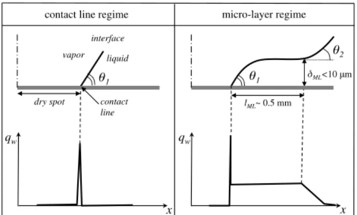
Nucleate boiling is a physical phenomenon encountered in a large number of engineering applications. Its features are some-times required, like in some heat transfer devices, and in other cir-cumstances not desirable, like for instance in cryogenics tanks in microgravity conditions. Despite the large amount of studies con-cerning nucleate boiling, there is still a number of unanswered questions, in particular related to the region beneath a bubble where for some conditions a micro-layer is formed and persists during the first part of the bubble growth. It is a tiny film, which has a thickness smaller than ten microns and a length up to the millimetre. Actually, we can distinguish between two regimes of nucleate boiling, like schematically illustrated inFig. 1where the region around the bubble foot is represented: the contact line (CL) regime and the micro-layer (ML) regime[26]. In contact line regime the bubble maintains a quasi-static equilibrium shape dur-ing its growth[10,19]. The contact line moves while the bubble grows and the interface maintains a slope with respect to the wall given by the contact angle h1. On the other hand, when the bubble growth is fast enough, it may happen that the contact line cannot move as fast as the bubble: consequently the interface is bended and a micro-layer is formed. We can thus distinguish between
two angles: the contact angle h1 formed at the contact line between the interface and the wall, and an apparent contact angle h2 which is given by the inclination of the interface outside the micro-layer.1 By locally inducing high temperature gradients, the
presence of a micro-layer strongly enhances the heat transfer between the solid heater and the bubble[21,9]. Therefore, one major difference between the two regimes is the wall heat flux profile qw which has only a peak at the contact line in the CL regime whereas it exhibits a peak at the contact line followed by a plateau along the micro-layer in the ML regime [9], as schematically shown in
Fig. 1. As a consequence, the micro-layer strongly affects the growth of the bubble, its departure diameter and frequency as well as its shape. Micro-layer effects have been observed experimentally since the pioneer work of Cooper and Lloyd[5]. However, micro-layers are thin and long and have a life time of only a few milliseconds which make the measurements tedious. More recently, the advance in tech-niques like high speed infrared thermography[25]and laser interfer-ometry[12]together with high-speed cameras, have permitted to obtain interesting experimental analysis showing the formation and depletion of micro-layers with quantitative data on their thick-ness and length temporal evolutions [3,21,55]. Experimental
⇑Corresponding author.
E-mail address:[email protected](A. Urbano).
1Note that h
1is also an apparent contact angle at the outlet of a micro-region and
it is related to a smaller microscopic angle hmic[26,27,38,11]. The micro region around
the contact line, smaller than the micron, is not the focus of the present work and will not be considered in our discussion. SeeAppendix Afor more details.
evidences of the transition between contact line and micro-layer regime have been reported recently in[9]for a configuration involv-ing a liquid meniscus movinvolv-ing on a heated wall. All these works have emphasised the importance of the micro-layer in the heat transfer process and the evidence that if a micro-layer exists it has to be taken into account in the nucleate boiling calculations[16]. Indeed numerical models have been developed to account for the micro-layer effects without directly solving it and are usually introduced in the numerical computations as boundary conditions[4,55]or as local source terms[43,44]. Recently, Hänsh and Walker[17]carried out a direct numerical simulation of the nucleation of a bubble with a resolved micro-layer beneath a bubble. However, they consider a purely hydrodynamic modelling without accounting for heat and mass transfer in their computation, but evaluating the evaporative mass flow rate from an offline computation. Differently, for what concerns CL regime, for which the grid refinement requirements are less stringent, fully resolved DNS simulations are available in the literature and have demonstrated their capability in correctly reproducing the phenomenon[27,45,48].
Several points remain unclear about the physical processes involved in the formation and depletion of micro-layers. In partic-ular, it is not fully understood for which conditions nucleate boil-ing occurs in contact line or in micro-layer regime. The main motivation of the present work is to provide detailed informations in order to characterise the transition between the regimes, using fully resolved Direct Numerical Simulations (DNS). The-in house solver DIVA has been used to solve the incompressible Navier-Stokes equations for two phase flows and to account for phase change. Axisymmetric configurations have been employed, with very refined grids allowing the description of a possible micro-layer having a thickness of the order of the micron, beneath a bub-ble having a radius of the order of the millimetre. Simulations of this multi-scale phenomenon are challenging and require using massively parallel supercomputers and suitable numerical tools to verify that the results are not affected by grid dependence effects. Moreover, it is noteworthy that micro-layers involve locally very high heat fluxes in the range of several MW, that could induce stability issues for numerical solvers if the thermal gradients are not sufficiently resolved. To the authors knowledge, there are no other DNS results with phase change available in the literature showing the formation and depletion of a micro-layer and the pre-sent work is the first attempt to carry out a fully resolved DNS of nucleate boiling in micro-layer regime.
In the next section the numerical solver is introduced, recalling the mathematical formalism and giving some details on the numerical methods that are implemented in the code. A simple axisymmetric domain is considered: details on the boundary
con-ditions and mesh requirements are given. A convergence study and a first comparison with experimental data in micro-layer regime are presented. The simulation of a bubble nucleation in layer regime, showing the formation and depletion of the micro-layer, is deeply analysed and the basic physical mechanisms driv-ing the phenomenon are interpreted. The influence of the main parameters is thus investigated with a parametric study varying the wall superheat, the contact angle, the surface tension and the liquid viscosity, and looking for the limit between CL and ML regimes. Eventually, a correlation for the frontier between the two regimes is proposed.
2. Numerical solver 2.1. Mathematical formalism
To describe the nucleate boiling at atmospheric pressure, in a isobaric environment, we consider an incompressible two-phase flow of a single component liquid-vapour system, with spatially uniform fluid densities
q
and thermophysical properties in each phase (viscosityl
, thermal conductivity k and specific heat at con-stant pressure cp). Moreover, we assume that the heat produced by viscous dissipation is negligible. Under these hypothesis the flow can be described by the following form of the conservation equa-tions of mass, momentum and energy in each phase:r
& V!¼ 0 ð1Þq
D V ! Dt ¼ +r
!! þpr
& ð2l
DÞ þq
g ! ð2Þq
cpDT Dt¼r
& ðkr
TÞ ð3Þwhere V! is the velocity field, p is the pressure, T is the temperature, D is the deformation tensor and g! is the gravity acceleration. The corresponding mass, momentum and energy jump conditions that must be satisfied at the interface C, accounting for the phase
change, are: ~ V h i C¼ _m 1
q
$ % C ~n ð4Þ p ½ .C¼rj
þ 2l
@Vn @n $ % C + _m2 1q
$ % C ð5Þ +kr
T & ~n ½ .C¼ _mLvap ð6Þwhere
r
is the surface tension,j
denotes the local interface curva-ture, n! is the normal vector at the interface, pointing towards the liquid phase, Vn is the velocity component in the n! direction, _m is the boiling mass flow rate and Lvapis the latent heat of vaporisa-tion. The operator ½:.Cindicates the jump across the interfaceCandis defined by:
½f .C¼ fv+ fl ð7Þ
with the subscripts l and
v
referring respectively to the liquid andvapour phases. Note that the present form of the energy jump con-dition Eq.(6)assumes that the interface temperature is equal to the saturation temperature (TC¼ Tsat) in accordance with the second law of thermodynamics for a pure liquid-vapour system at local thermodynamic equilibrium. Moreover, for the sake of simplicity, we assume that Tsatis constant, which implies that the surface ten-sion
r
is constant. As a consequence, Marangoni convection effects (due to Kelvin effects for instance) are neglected. Interested readers can find more details on this specific point in[22].contact line regime micro-layer regime
dry spot 1 liquid interface vapor contact line qw x 1 2 ML<10 m lML~ 0.5 mm qw x
Fig. 1. Scheme of the different nucleate boiling regimes, contact line (left) and micro-layer (right), in terms of interface shape at the bubble foot (up) and wall heat flux profile (down).
2.2. Numerical schemes
The in house solver DIVA is used to carry out the numerical analysis in the present work. It is a structured incompressible sol-ver, for two-phase flows simulations which is based on the Ghost Fluid Method [8,23,29,31,51], allowing a sharp discretisation of the jump conditions across the interface, and on the Level Set method to compute the motion of the interface[36]. A preserving distance algorithm ensures the signed distance property of the Level Set function in the whole domain[50]. Following the general guidelines of the Ghost Fluid Method, phase change simulations can be considered by imposing additional jump conditions to maintain mass conservation[35], energy conservation[14,15,54]
and chemical species conservation [37,53,41]. Moreover, as demonstrated in[54], global accuracy of the numerical solver can be improved with second order extrapolations for the temperature field performed with the numerical methods described in[1]. Fifth order WENO-Z schemes are used for the convective terms[2], sec-ond order finite differences for the diffusion terms. A Black-Box MultiGrid solver[7] permits a fast and stable resolution of the pressure Poisson equation which comes out from the projec-tion method, with a computaprojec-tional time only weakly dependent on the density ratio[32]. The temporal integration is performed with a second order Runge-Kutta scheme. Our in house solver also permits computations involving compressible two-phase flows
[18]and the simulation of complex geometries on structured grid making use of an Immersed Interface Method for both single phase flows[34]and two-phase flows[30]. The solver has been exten-sively validated with experimental data both for isothermal two-phase flows [28,52]and for two-phase flows with phase change for impacting droplets in the Leidenfrost regime[42]and for nucle-ate pool boiling[19]. In particular, Huber et al.[19]have presented detailed comparisons between numerical results and experimental data on nucleate boiling in contact line regime, showing the ability of the solver in retrieving the correct departure diameter and departure frequency of a single bubble detaching from a nucleation site. This work showed, with a grid sensitivity analysis, that a grid cell size of about 10
l
m is required in the vicinity of the contact line in order to achieve well resolved simulations of nucleate boil-ing in contact line regime. The simulations of boilboil-ing flows carried out in the present paper and in the former studies[14,19,54]are based on a Ghost Fluid Thermal Solver for Boiling (GFTSB) for com-puting the heat transfer and the phase change around the interface[41].
3. Configuration and numerical validations 3.1. Computational domain and initial conditions
The axisymmetric computational domain that is considered in the present study is shown inFig. 2(a). It is a square of L dimension, limited by an isothermal wall in y ¼ 0, an adiabatic wall in x ¼ L and opened in y ¼ L. A symmetry condition is inferred in x ¼ 0. Dirichlet conditions on the temperature are applied in y ¼ 0, and Neumann conditions in x ¼ L and y ¼ L. For the velocity field, no slip conditions are considered at the walls, whereas a free bound-ary condition is used at the upper boundbound-ary (y ¼ L).
The considered fluid is water at atmospheric conditions and the corresponding thermophysical properties are reported inTable 1. The sea level value for the gravity acceleration is used, g ¼ 9:81 m & s+2. The initial thermal field is constant and equal to Tsat¼ 373:12 K everywhere except in a layer near the isothermal wall where a linear profile is applied from Tsatto Tw. The thickness of the thermal layer dKC is computed from the correlation of Kays and Crawford[24]for free convection given by Eq.(8):
dKC¼ 7:14
l
la
lq
lgblðTw+ TsatÞ& '1=3
ð8Þ
In Eq.(8),
al
denotes the liquid thermal diffusivity and bl the isobaric thermal expansion coefficient of the liquid, which is equal to bl¼ 7:52 / 10+4K+1for water at atmospheric conditions.A vapour seed is initially deposited in x ¼ y ¼ 0 as shown in
Fig. 2(a). The initial shape of the seed is reported in the zoom view ofFig. 2(b): it is a circle of radius Rsshifted upward in order to have the desired contact angle h at the wall. The same contact angle will then be imposed during the computation with the Neumann boundary condition on the Level Set function2 (see Huber et al.
[19]for more details). 3.2. Mesh requirements
Preliminary simulations have been carried out to find the required level of grid refinement to capture hydrodynamic and thermal effects leading to the formation of a micro-layer. For this study we have considered a square of side L ¼ 2 mm (seeFig. 2). The initial seed has a radius Rs¼ 60
l
m and the imposed contact angle is h ¼ 500. The wall temperature is Tw¼ 393:12 K which cor-responds to a Jakob number Ja ¼ 60 defined by Eq.(9):
Ja ¼
q
lcplðTw+ TsatÞq
vLvapð9Þ
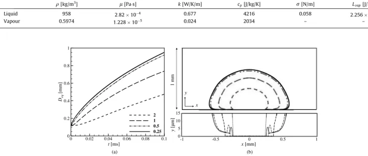
Four uniform grids, with equal resolutions in both Cartesian directions, have been used. The cell size of the grids are equal to 2, 1, 0.5 and 0.25
l
m which correspond respectively to 10242, 20482, 40962and 81922elements. Simulations on the latter two grids have been performed respectively on 64 and 256 processors by using the MPI library for parallel computations. A total time of 0.1 ms has been computed, which is sufficient to observe the for-mation of the micro-layer. Results are shown inFig. 3in terms of temporal evolution of the equivalent vapour diameter Deq(a) and bubble shapes at t ¼ 0:1 ms (b) for the different mesh resolutions. Also a detail of the interface in the region near the wall is reported inFig. 3(c) to help the visualisation of the region where the micro-layer is formed (note that this image is not scaled to help the visu-alisation of the micro-layer). First, we observe that a micro-layer is present in the simulations with the two finer grids (cell size equal to 0.25 and 0.5l
m), whereas no micro-layer is found with the two coarser grids (1 and 2l
m). This can be explained considering that in order to simulate the thin micro-layer, the grid must be fine enough to correctly describe the hydrodynamic scales associatedFig. 2. Configuration used for the axisymmetric numerical simulations. (a) Com-putational domain, initial condition and boundary conditions. (b) Zoom view of the vapour seed which is used in the initial condition.
2The imposed angle h is an apparent contact angle corresponding to h
1inFig. 1. See
with its formation. Otherwise, if the simulation is under resolved, a contact line regime is retrieved and this strongly affects the results. In fact, as illustrated inFig. 3(a), with the 1 and 2
l
m meshes, the growth rate is strongly underestimated with differences with respect to the 0.25l
m mesh up to 54% and 24% respectively for Deq. On the other hand, only slight differences, smaller than 4%, are observed between the two finest grids, which demonstrates the good spatial convergence of these simulations when suffi-ciently refined grids are employed. Both the finest grids permit to compute the formation of the micro-layer despite slight differ-ences around the contact line position. The micro-layer has a min-imum thickness around 2l
m, which corresponds to 4 grid points for the 0.5l
m mesh. The instantaneous field of velocity vectors at t ¼ 0:1 ms, obtained with the 0.5l
m mesh, is plotted inFig. 4around the whole bubble, (a), and around the micro-layer, (b) and (c). These figures allow the visualisation of the strong velocity jump across the interface, induced by the very high thermal flux in the micro-layer region which leads to a strong evaporation of the liquid in the layer. We can conclude from these results that the 0.5
l
m mesh is suitable to simulate the formation of the micro-layer during nucleate boiling of a bubble, and it will be used to carry out the simulations of the present study.It is noteworthy that the simulations of this work are the first to fully resolve the hydrodynamic and thermal effects initiating the formation of a micro-layer at very low scale. This has been made possible by using the same numerical solver in the whole compu-tational domain thanks to recent advances in the field of numerical methods for DNS of two-phase flows with phase change.
3.3. Micro-layer and contact line regimes
We are now concerned about the ability of the solver to differ-entiate between nucleate boiling in contact line or micro-layer regime, in the configuration presented in the previous section, if the 0.5
l
m grid is used. Another case has thus been simulated, keeping the same conditions of the above convergence study case, except for the wall temperature which has been lowered to Tw¼ 380:12 K which corresponds to Ja ¼ 21. These are the condi-tions of the experimental data of Son et al.[48]for nucleate boiling in contact line regime, for which the DIVA solver has beenprevi-ously validated in the recently published work by Huber et al.
[19].3 As expected nucleate boiling occurs in contact line regime
for Ja ¼ 21. The instantaneous bubble interface, the temperature field and the wall heat flux profile at t ¼ 0:2 ms are shown in
Fig. 5(a) for Ja ¼ 21 in contact line regime and in Fig. 5(b) for Ja ¼ 60 in micro-layer regime (which is the case of the convergence study).
It appears that the micro-layer formation strongly modifies the bubble shape which becomes more flat than the bubble in contact line regime, which keeps an almost spherical shape. Another major consequence of the micro-layer is observable in the wall heat flux profile. In CL regime qw only shows a peak at the contact line, whereas in ML regime qwshows a peak at the contact line and then remains high all along the micro-layer extension, as was schemat-ically introduced in Section1(seeFig. 1). These results show that the present setup is suitable to investigate on the transition from contact line to micro-layer regime.
3.4. Micro-layer thickness and length
To quantitatively verify our results in ML regime, we have car-ried out a simulation with the same configuration (seeFig. 2) but in conditions that are in the range of the experimental data of Jung and Kim[21], that is Tw¼ 396:12 K corresponding to Ja ¼ 69, and a contact angle of h ¼ 650. The aim of this analysis is to verify that the micro-layer characteristics that we compute are in agreement with experimental observations in similar conditions. The experi-mental observations report the formation of a micro-layer with a thickness dML;exp< 3
l
m and an extension lML;exp1 0:15 + 0:6 mm. These values have been deduced from Fig. 7 and 8 in[21]. The numerical results also show the formation of a micro-layer as observable inFig. 6where the instantaneous shape of the micro-layer and the temperature field are reported. As a measure of dML we consider the minimum micro-layer thickness and lMLis evalu-ated as the distance between the radial position where the slope of the interface w becomes greater than 100 and the contact lineTable 1
Thermophysical conditions for water in liquid and vapour phase at atmospheric pressure and Tsat¼ 373:12 K.
q[kg/m3] l[Pa&s] k [W/K/m] c
p[J/kg/K] r[N/m] Lvap[J/kg]
Liquid 958 2:82 / 10+4 0.677 4216 0.058 2:256 / 106
Vapour 0.5974 1:228 / 10+5 0.024 2034 – –
Fig. 3. Temporal evolution of the equivalent vapour diameter (a), bubble shape at t ¼ 0:1 ms (b, up) and zoom of the bubble shape nearby the heated wall at t ¼ 0:1 ms (b, down) for several levels of grid refinement (cell size equal to 0.25/0.5/1 and 2lm).
3 Note that the grid resolution used in the validations carried out in[19]is 10lm,
which is a sufficient resolution to capture the detachment diameter in quasi-static conditions which arise from a force balance.
position (seeFig. 6). The micro-layer thickness dMLvaries between 2 and 3
l
m, its extension lMLis around 0.3 mm and their temporal evolutions are reported inFig. 6together with the bubble equiva-lent radius. These values are in the range of the experimental data which demonstrate that the present numerical simulations are able to reproduce the micro-layer regime if it occurs.44. Numerical analysis of the growth and depletion of a micro-layer
This section is dedicated to the analysis of the formation and depletion of a micro-layer. For this purpose we have selected a square domain of dimension L ¼ 3 mm, which is greater than the previous domain, to allow the bubble to grow more, until the
4Note that the temporal evolutions of the experimental data are slower than the
numerical evolutions, which can be explained by the fact that, in a first approxima-tion, we are imposing an isothermal boundary condition without accounting for the wall temperature variation due to heat conduction in the solid heater.
Fig. 4. Velocity vectors for the whole bubble (a) and zoom views around the micro-layer region (b and c) for the results of the 0.5lm grid at t ¼ 0:1 ms.
q
w[MW/m
2]
1 mm
y
x
-1 -0.5 0 0.5 1 0 5 10x
[mm]
q
w[MW/m
2]
1
m
m
y
x
-1 -0.5 0 0.5 1 0 5 10x
[mm]
Fig. 5. Bubble interface, temperature field and wall heat flux profile at t ¼ 0:2 ms in contact line regime for Ja ¼ 21 (a) and in micro-layer regime for Ja ¼ 60 (b).
Fig. 6. Results for Ja ¼ 69 and h ¼ 650. Micro-layer visualisation and temperature
field at t ¼ 0:29 ms (a). Temporal evolution of the equivalent bubble radius reb,
micro-layer depletion. The mesh has a uniform resolution of 0.5
l
m in a 1 mm square from the nucleation site (0 < x < 1 mm and 0 < y < 1 mm), and it is coarsened towards y ¼ L and x ¼ L up to 1.5l
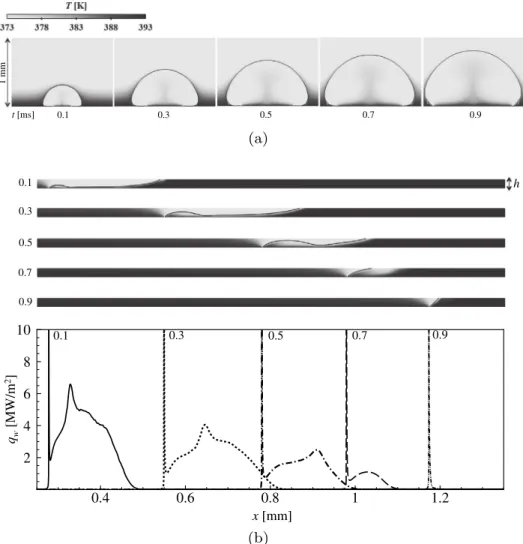
m (note that the most coarsened regions are not reached by the bubble). The same boundary conditions of the convergence case are inferred that is Ja ¼ 60 and h ¼ 500. A total physical time of 1.5 ms has been simulated. A micro-layer is formed and depleted in less than 1 ms, as can be observed inFig. 7(a) where 5 instanta-neous fields of temperature and bubble interfaces are reported, in a temporal interval that goes from 0.1 to 0.9 ms. Zoomed views in a fixed rectangular box of 1.1 mm length and 20l
m height are shown inFig. 7(b) for the same 5 temporal instants together with the corresponding wall heat flux profiles. The wall heat flux ini-tially has a profile similar to that expected in a ML regime (c.f.Fig. 1). The micro-layer length increases (t ¼ 0:3 ms) and then
decreases up to its disappearance. At t ¼ 0:9 ms the heat flux pro-file has the typical peak shape of the CL regime.
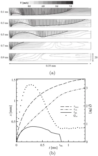
An amplified view of the micro-layer formation and depletion is shown in the velocity magnitude fields for the same five temporal instants inFig. 8(a): streamlines coloured with the axial velocity (
v
y) are also reported. At t ¼ 0:1 ms, the interface is bended justafter the contact line and forms a rim followed by a very tiny film of liquid, with a thickness approximately equal to 3
l
m. Note that a rim has also been observed in the numerical results of Hänsh et al.[17], which are based on an hydrodynamic formulation (no heat transfer). Actually, this interface shape is typical of dewettingphenomena: when a hole is nucleated on a film substrate the liquid retracts and a rim is formed which collects the liquid removed from the dry region, like shown for instance in the experiments of Redon et al. [39,40]. Similar observations have also been reported in the experimental work by Fourgeaud et al. [11] on the dynamic of a dewetting film with evaporation. For what con-cerns the micro-layer, the shape of the rim impacts the heat flux profile ofFig. 7(b), showing a secondary peak at the radial position corresponding to the minimum height of the interface between the rim and the film. In the rim the flow induced by the contact line movement is parallel to the wall, whereas, in the liquid film the flow is almost at rest. The micro-layer length increases from t ¼ 0:1 ms to t ¼ 0:3 ms and then decreases. Actually, when the rim grows, it pushes out the liquid film, which eventually disap-pears. At t ¼ 0:7 ms the interface appears just slightly bended and at t ¼ 0:9 ms it has a constant slope like in the CL regime. These observations suggest that the micro-layer depletion is an hydrody-namic phenomenon, which is different than the usually adopted hypothesis of the micro-layer being depleted by evaporation of the film[5,43]. The micro-layer shape is such that the slope of the interface is equal to h at the contact line position, and then decreases along the radial direction, goes down around zero along the layer extension and then grows up again after the micro-layer end. Therefore, a good indicator of the micro-micro-layer length lML is the distance between the radial position where the interface slope is equal to the contact angle (w ¼ h) and the contact-line
0.1 t [ms] 0.3 0.5 0.7 0.9 1 mm 0.1 0.9 0.7 0.5 0.3 h
0.4
0.6
0.8
1
1.2
2
4
6
8
10
0.1 0.3 0.5 0.7 0.9x
[mm]
q
w[MW/m
2]
Fig. 7. (a) Instantaneous interface shapes and temperature fields of a bubble nucleated in micro-layer regime, with Ja ¼ 60 and h ¼ 500(same grey scale ofFig. 3), for 5
temporal instants. (b) Zoom on a fixed box of dimensions h ¼ 20lm and Dx ¼ 1:1 mm, and corresponding wall heat flux profiles, for the same 5 instants (saturated scale at 10 MW/m2).
position (seeFig. 6(a)). To follow the formation and depletion of the micro-layer, the temporal evolution of lML is shown inFig. 8 (b) where the radial position of the contact line xCLand the maxi-mum interface position ximax (seeFig. 2) have also been reported. Initially the velocity of the bubble growth is higher than the con-tact line speed: as a consequence the interface is stretched in the radial direction and ends up forming a micro-layer as shown by the lML growth. After t ¼ 0:3 ms, lML decreases, as a consequence of the micro-layer depletion and goes to zero around tML= 0.85 ms, which is the lifetime of the present micro-layer, in agreement with the instantaneous field shown inFig. 8(a). The wall heat flux is strongly affected by the micro-layer and its integrated value from x ¼ 0 to x ¼ L is also reported in the same figure (Qint). It increases during the micro-layer growth and decreases during its depletion towards an almost constant value when a contact line regime is retrieved.5
5. Frontier between contact line and micro-layer regime We may now investigate on the physical parameters that favour the formation of a micro-layer during the bubble growth. The development of the micro-layer seems to be originated by the dif-ference between the velocity of the bubble expansion and the con-tact line velocity. Therefore, we can speculate that the micro-layer
creation results from a balance between the strength of the bubble growth rate, the capillary actions and the viscous dissipation acting on the contact line in the liquid region. The growth rate of the bub-ble can be related to the Ja number (defined by Eq.(9)), which is expected to be a driving parameter. The viscous dissipative force in the liquid rim is related to both the liquid viscosity
ll
and the liquid velocity, also related to the Ja number. Therefore, we expect a higher liquid viscosity to increase the dissipation and to facilitate the micro-layer formation. The capillary actions participate to the braking of the contact line on the one hand and against the bending of the interface, and thus the formation of the micro-layer, on the other hand. Actually, we expect the wettability of the fluid to have a major influence and this can be summarised by the spreading coefficient S which, for partial wetting conditions, is given by:S ¼
r
ðcos h + 1Þ ð10ÞThe spreading coefficient is negative, and tends towards zero for complete wetting[13]. Higher
r
and h characterise a lower wetta-bility and thus are expected to prevent the micro-layer formation. On the contrary, lowerr
and h should help the micro-layer forma-tion. In conclusion, we expect the most significant parameters affecting the micro-layer formation to be the Ja number, the con-tact angle h, the liquid viscosityl
land the surface tensionr
.A parametric study has been performed to fully investigate the influence of the above parameters. The selected domain is a square of dimension L ¼ 2 mm, and a uniform grid with a cell size equal to 0.5
l
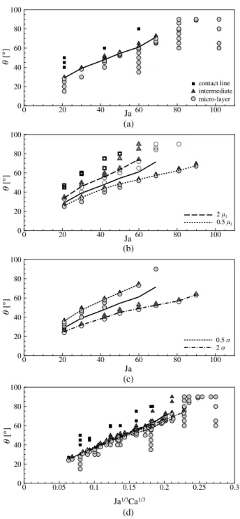
m is used (see3.2). The first group of simulations have been carried out considering the thermophysical properties of water at atmospheric pressure (see Table 1). The same configuration of the previous cases is adopted (Fig. 2). We have varied the Ja num-ber from 20 to 100 (by varying the wall temperature Tw) and for each Ja number several simulations with different contact angles h, from 25! to 90!, have been carried out. The simulated physical time for each computation is 0.04 ms, which is sufficient to observe if a micro-layer is formed or not. Results are reported inFig. 9(a) where a circle indicates a micro-layer regime, a square a contact line regime. Intermediate situations (for instance a strongly bended interface without a film creation) have been identified with triangles. A solid curve has also been reported to identify the limit between the regions of micro-layer and contact line regimes. The results show that for a given Ja, a limit contact angle exists under which a micro-layer is formed. For higher Ja the limit contact angle increases, showing that higher Jakob numbers facilitate the micro-layer formation. In our simulations, a micro-micro-layer is always present for Ja > 70 in the range of h investigated (that is for the maximum investigated h ¼ 900a micro-layer regime is obtained).To investigate the influence of
l
l andr
, the same simulations have been carried out doubling or halvingl
l andr
, keeping all the other parameters constant. Results are shown inFig. 9(a) for the viscosity variation and inFig. 9(c) for the surface tension vari-ation. The limit curve obtained for water (Fig. 9(a)) has also been reported in these figures for comparison. These curves show that increasingl
lfacilitates the micro-layer regime which, for a given h, is found for lower Ja. On the contrary, a higherr
plays against the layer formation, and for a given contact angle, a micro-layer is formed for higher Ja. These results are in qualitative agree-ment with the suggested impact of the viscous forces and the sur-face tension on the micro-layer formation.All these results can be summarised in one single curve if the proper dimensionless variables are selected. For that purpose, let us introduce a capillary number Ca for the present problem:
Ca ¼
l
lv
intr
ð11Þwhere
v
intrepresents an indicator of the bubble growth velocity,normal to the interface. We are concerned with the first instants
V [m/s] 0.9 ms 0.7 ms 0.5 ms 0.1 ms 0.3 ms 20 m 0.35 mm 0 0.5 1 0.5 1 1.5 0 1 2 3 ximax xCL lML Qint t [ms] tML x [mm] Q [W]
Fig. 8. Velocity fields and streamlines coloured by the axial velocityvy for five
temporal instants, in a constant dimension box moving with the contact line (a). Temporal evolution of the contact line position xCL, the bubble maximal interface
position ximax, the micro-layer length lMLand the integrated wall heat flux Qint(b).
5 Note that these are the first instants after the bubble nucleation: for longer times,
after nucleation, when a global estimation of
v
intis given by theexpansion velocity of the bubble induced by the phase change:
v
int2 qwq
vLvap ð12ÞIn Eq.(12)the evaporation mass flow rate _m has been expressed as a function of the wall heat flux qwwhich can be related to the thickness dKCof the thermal boundary layer that has been initially imposed (see Eq.(8)):
qw¼ kl
ðTw+ TsatÞ
dKC ð13Þ
Making use of Eqs. (12), (13) and (9), after some rearrange-ments, Eq.(11)gives:
Ca ¼ Ja
a
l dKCl
lr
ð14Þwhere
al
is the liquid thermal diffusivity. Being Ja the other dimen-sionless number considered, we are looking for a proper combina-tion JaaCab permitting to summarise the results. The best fit is found for a ¼ b ¼13as shown inFig. 9(d), where all the numerical results of the present parametric study have been reported, and which corresponds to the following condition to have a micro-layer regime: Ja Ca h+ h0 ð Þ3> 1 A3 ð15Þ
where h0¼ 50 and A ¼ 313, valid in the range of the interpolated results that is for 2:2 / 10+4
< Ca Ja < 1:2/ 10+2 and 150< h < 900. Note that the correlation Eq.(15)has been deduced in wall isothermal conditions which correspond to the limit case of Biot number Bo ! 0. In terms of dimensional quantities, Eq.
(15) corresponds to the following limit for the interface velocity
v
int:v
int> 1 A3=2 ffiffiffiffiffiffiffiffiffiffiffiffiffiffiffiffiffiffiffiffiffiffiffiffiffiffiffiffiffiffiffiffiffiffia
l dKCr
l
l ðh + h0Þ3 r ð16ÞThe square root term in Eq.(16)can be interpreted as the pro-duct of two characteristic velocities:
3 a capillary velocity
v
4dgiven by the following expression:v
4d¼r
l
lðh + h0Þ3 ð17Þ
which is the characteristic velocity related to the dewetting of a film when a hole is nucleated, and depends on a balance between the capillary forces and the dissipative viscous forces in the dewetting rim6[11,39,47];
3 a velocity associated with the phase change
v
4m:v
4m¼a
ldKC ð19Þ
which is the velocity of heat diffusion through the thermal boundary layer.
Eq.(16)suggests that a micro-layer is formed beneath a nucle-ated bubble if the bubble growth is faster than the maximal veloc-ity that the contact line can have, which depends on the thermophysical properties of the fluid, and corresponds to a com-bination of the dewetting velocity and the velocity locally induced by the phase change at the contact line.
6. Conclusion
The first DNS of a nucleated bubble showing the formation and depletion of a micro-layer has been carried out and analysed in the present work. The shape of the micro-layer, showing a rim fol-lowed by a film, is similar to a dewetting film. This has suggested a mechanism for the micro-layer depletion induced by capillary actions. It has been shown that fine grid resolutions, under the half
l
m, are necessary to capture the micro-layer, that only measures a few microns height. However, the presence of a micro-layer strongly influences both the shape of the bubble and the wall heat flux at larger scales. Therefore, knowing what is the nucleateboil-0 0.05 0.1 0.15 0.2 0.25 0.3 0 20 40 60 80 100 Ja1/3Ca1/3
(d)
(c)
0 20 40 60 80 100 0 20 40 60 80 100 Ja 0.5 2 0 20 40 60 80 100 0 20 40 60 80 100 Ja 2 l 0.5 l(b)
0 20 40 60 80 100 0 20 40 60 80 100 Ja(a)
contact line intermediate micro-layerFig. 9. Results of the parametric study on the transition from micro-layer to contact line regime. (a) Water, properties ofTable 1. (b) Open symbols: 2ll, closed symbols:
0:5ll. (c) Open symbols: 2r, closed symbols: 0:5r. (d) All the results.
6 Usually the velocity of the dewetting film is given by:
v
d¼ kv
4d ð18Þwhere k is a constant depending on the molecular weight and the nature of the fluid[39].
ing regime is of major interest to correctly predict the wall heat flux profile, either by fully solving the micro-layer or by using an integrated model for the micro-layer. A parametric study has thus been carried out to investigate on the transition between the two regimes. This has permit to find a correlation for the limit in terms of Ja number, Ca number and apparent contact angle h. The corre-lation could help in knowing a priori the nucleate boiling regime and thus in improving the heat flux profile prediction. Moreover, the results have shown that the formation of the micro-layer occurs if the bubble grows faster than a limit velocity for the con-tact line which depends on the dewetting velocity, related to vis-cous and capillary forces, and on the liquid thermal diffusion through the thermal boundary layer.
Acknowledgements
The authors gratefully acknowledge the CNES (Centre National d’Études Spatiales) and Air Liquide Advanced Technologies for the financial support of the present postdoctoral study.
The authors gratefully acknowledge the French National Research Agency (ANR) for financial support of the postdoctoral study of Mathieu Lepilliez for the development of a massively par-allel version of the Black-Box multigrid method for solving linear systems in the frame of the COALA project ANR-15-CE06-0013.
The authors gratefully acknowledge the CNRS (Centre National pour la Recherche Scientifique) for funding compensation of teach-ing hours to Sebastien Tanguy durteach-ing the year 2017–2018.
This work was granted access to the HPC resources of CALMIP supercomputing center under the allocation 2017-P17035. Appendix A. Contact angles
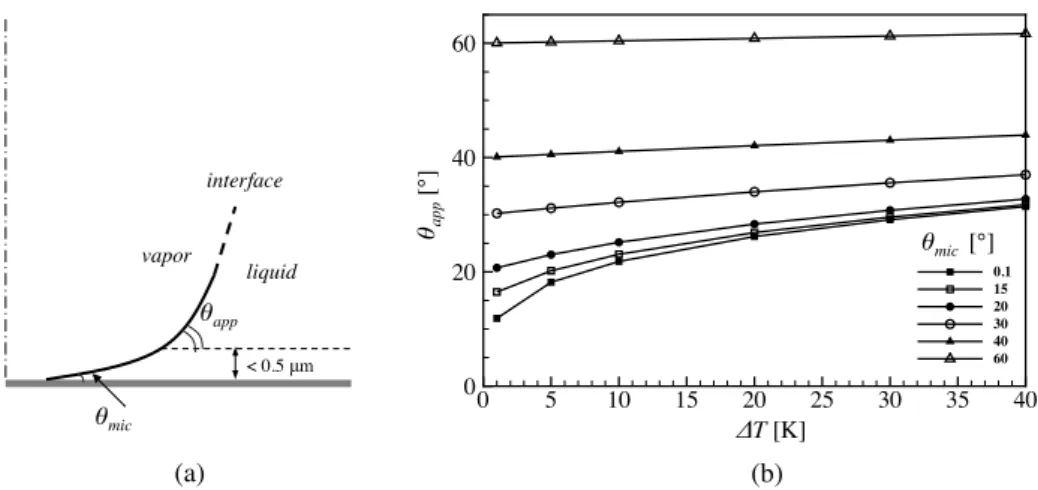
The static microscopic contact angle hmic formed between a liquid-vapour interface and a solid wall results from an energetic balance at the contact line, and depends on the nature of both the fluid and the solid[46]. Wettable fluids are characterised by static contact angles hmicclose to zero. In the framework of bubble nucleated on a superheated wall a micro-region exists, having a characteristic dimension of the order of 100 nm, where the inter-face is bended. In the micro-region the interinter-face slope varies between hmic at the wall and the apparent contact angle happ, as schematically shown inFig. A.10(a)[27,38]. Micro-region models allow to compute happ as a function of the wall superheat
DT ¼ Tw+ Tsat for a given fluid with a given hmic. As an example, in Fig. A.10(b) are reported the evolutions of happ obtained with
Mathieu model [33]which is a generalisation of Stephan model
[49], and that has been analysed in the framework of nucleate boil-ing in contact line regime by Huber et al.[19]. In particular, these curves show that high values of hmicinvolve small variations of happ. In the present simulations, we impose the angle between the interface and the wall with a boundary condition on the level set function (see[19]for the numerical details). The grid cell size is equal to 0.5
l
m and therefore it does not allow to capture the micro-region that should be smaller than 0.1l
m. As a conse-quence, the imposed contact angle h must be considered an appar-ent contact angle. Moreover, note that the conditions analysed in the present work refer to Ca numbers, based on the velocity of the contact line, around 0.02. As a consequence of these small val-ues, we have neglected the variation of the contact angle induced by dynamic effects[6,20,46].References
[1]T.D. Aslam, A partial differential equation approach to multidimensional extrapolation, J. Comput. Phys. 193 (2003) 349–355.
[2]R. Borges, M. Carmona, B. Costa, W. Don, An improved weighted essentially non-oscillatory scheme for hyperbolic conservation laws, J. Comput. Phys. 227 (2008) 3191–3211.
[3]Z. Chen, A. Haginiwa, Y. Utaka, Detailed structure of microlayer in nucleate pool boiling for water measured by laser interferometric method, Int. J. Heat Mass Transf. 108 (2017) 1285–1291.
[4]Z. Chen, Y. Utaka, On heat transfer and evaporation characteristics in the growth process of a bubble with microlayer structure during nucleate boiling, Int. J. Heat Mass Transf. 81 (2015) 750–759.
[5]M.G. Cooper, A.J.P. Lloyd, The microlayer in nucleate pool boiling, Int. J. Heat Mass Transf. 12 (1968) 895–913.
[6]R.G. Cox, The dynamics of the spreading of liquids on a solid surface. Part 1. Viscous flow, J. Fluid Mech. 168 (1986) 169–194.
[7]J.E. Dendy, Black box multigrid, J. Comput. Phys. 48 (1982) 366–386. [8]R.P. Fedkiw, T. Aslam, B. Merriman, S. Osher, A non-oscillatory Eulerian
approach to interfaces in multimaterial flows (the ghost fluid method), J. Comput. Phys. 152 (1999) 475–492.
[9]S. Fischer, T. Gambaryan-Roisman, P. Stephan, On the development of a thin evaporating liquid film at a receding liquid/vapour-interface, Int. J. Heat Mass Transf. 88 (2015) 346–356.
[10] S. Fischer, S. Herbert, E.M. Slomski, P. Stephan, M. Oechsner, Local heat flux investigation during pool boiling single bubble cycles under reduced gravity, Heat Transf. Eng. 35 (5) (2014) 482–491.
[11]L. Fourgeaud, E. Ercolani, J. Duplat, G. Gully, V.S. Nikolayev, Evaporation-driven dewetting of a liquid film, Phys. Rev. Fluids 1 (2016) 041901(R).
[12]M. Gao, L. Zhang, P. Cheng, X. Quan, An investigation of microlayer beneath nucleation bubble by laser interferometric method, Int. J. Heat Mass Transf. 57 (2012) 183–189.
[13]P.G. Gennes, Wetting: statics and dynamics, Rev. Mod. Phys. 57 (3) (1985) 827–863.
[14]F. Gibou, L. Chen, D.Q. Nguyen, S. Banerjee, A level set based sharp interface method for the multiphase incompressible Navier-Stokes equations with phase change, J. Comput. Phys. 222 (2007) 536–555.
Fig. A.10. (a) Schematic of the micro-region near the contact line of a bubble. (b) Evolution of the apparent contact angle happwith the wall superheating DT for different
[15]F. Gibou, R.P. Fedkiw, L.-T. Cheng, M. Kang, A second-order-accurate symmetric discretization of the poisson equation on irregular domain, J. Comput. Phys. 176 (2002) 2005–2227.
[16]G. Giustini, S. Jung, H. Kim, S. Walker, Evaporative thermal resistance and its influence on microscopic bubble growth, Int. J. Heat Mass Transf. 101 (2016) 733–741.
[17]S. Hänsh, S. Walker, The hydrodynamics of microlayer formation beneath vapour bubbles, Int. J. Heat Mass Transf. 102 (2016) 1282–1292.
[18]G. Huber, S. Tanguy, J. Béra, A time splitting projection scheme for compressible two-phase flows. Application to the interaction of bubbles with ultrasound waves, J. Comput. Phys. 302 (2015) 439–468.
[19]G. Huber, S. Tanguy, M. Sagan, C. Colin, Direct numerical simulation of nucleate pool boiling at large microscopic contact angle and moderate Jakob numbers, Int. J. Heat Mass Transf. 113 (2017) 662–682.
[20]V. Janecˇek, F. Doumenc, B. Guerrier, V.S. Nikolayev, Can hydrodynamic contact line paradox be solved by evaporation-condensation?, J Coll. Int. Sci. 460 (2015) 329–338.
[21]S. Jung, H. Kim, An experimental method to simultaneously measure the dynamics and heat transfer associated with a single bubble during nucleate boiling on a horizontal surface, Int. J. Heat Mass Transf. 73 (2014) 365–375. [22]D. Juric, G. Tryggvason, Computations of boiling flows, Int. J. Multiphase Flow
24 (3) (1998) 387–410.
[23]M. Kang, R.P. Fedkiw, X.-D. Liu, A boundary condition capturing method for multiphase incompressible flow, J. Sci. Comput. 15 (2000) 323–360. [24]W. Kays, M. Crawford, B. Weigand, Convective Heat and Mass Transfer, fourth
ed., McGraw Hill, 2003.
[25]H. Kim, J. Buongiorno, Detection of liquid-vapor-solid triple contact line in two-phase heat transfer phenomena using high-speed infrared thermometry, Int. J. Multiphase Flow (2011) 166–172.
[26]J. Kim, Review of nucleate pool boiling bubble heat transfer mechanisms, Int. J. Multiphase Flow 35 (2009) 1067–1076.
[27]C. Kunkelmann, P. Stephan, Numerical simulation of the transient heat transfer during nucleate boiling of refrigerant HFE-7100, Int. J. Refrig. 33 (2010) 1221– 1228.
[28]B. Lalanne, N.A. Chebel, J. Vejrazˇka, S. Tanguy, O. Masbernat, F. Risso, Non-linear shape oscillations of rising drops and bubbles: experiments and simulations, Phys. Fluids 27 (2015) 123305.
[29]B. Lalanne, L.R. Villegas, S. Tanguy, F. Risso, On the computation of viscous terms for incompressible two-phase flows with level set/ghost fluid method, J. Comput. Phys. 301 (2015) 289–307.
[30]M. Lepilliez, E.R. Popescu, F. Gibou, S. Tanguy, On two-phase flow solvers in irregular domains with contact line, J. Comput. Phys. 321 (2016) 1217–1251. [31]X.-D. Liu, R.P. Fedkiw, M. Kang, A boundary condition capturing method for poisson’s equation on irregular domains, J. Comput. Phys. 160 (2000) 151–178. [32]S. MacLachlan, J. Tang, C. Vuik, Fast and robust solvers for pressure-correction
in bubbly flow problems, J. Comput. Phys. 227 (23) (2008) 9742–9761. [33] B. Mathieu, Études physique, expérimentale et numérique des mécanismes de
base intervenant dans les écoulements diphasiques en micro-fluidique (PhD thesis), Université de Provence, 2003.
[34]Y. Ng, C. Min, F. Gibou, An efficient fluid–solid coupling algorithm for single-phase flows, J. Comput. Phys. 228 (2009) 8807–8829.
[35]D.Q. Nguyen, R.P. Fedkiw, M. Kang, A boundary condition capturing method for incompressible flame discontinuities, J. Comput. Phys. 172 (2001) 71–98. [36]S. Osher, J. Sethian, Fronts propagating with curvature-dependent speed:
algorithms based on Hamilton–Jacobi formulations, J. Comput. Phys. 79 (1988) 12–49.
[37]J. Papac, F. Gibou, C. Ratsch, Efficient symmetric discretization for the Poisson, heat and Stefan-type problems with Robin boundary conditions, J. Comput. Phys. 229 (2010) 875–889.
[38]R. Raj, C. Kunkelmann, P. Stephan, J. Plawsky, J. Kim, Contact line behavior for a highly wetting fluid under superheated conditions, Int. J. Heat Mass Transf. 55 (2012) 2664–2675.
[39]C. Redon, F. Brochard-Wyart, F. Rondelez, Dynamics of dewetting, Phys. Rev. Lett. 66 (6) (1991) 715–719.
[40]C. Redon, J.B. Brzoska, F. Brochard-Wyart, Dewetting and slippage of microscopic polymer films, Macromolecules 27 (1994) 468–471.
[41]L. Rueda-Villegas, R. Alis, M. Lepilliez, S. Tanguy, A ghost fluid/level set method for boiling flows and liquid evaporation: application to the Leidenfrost effect, J. Comput. Phys. 316 (2016) 789–813.
[42]L. Rueda-Villegas, S. Tanguy, G. Castanet, O. Caballina, F. Lemoine, Direct numerical simulation of the impact of a droplet onto a hot surface above the Leidenfrost temperature, Int. J. Heat Mass Transf. 104 (2017) 1090–1109. [43]Y. Sato, B. Niceno, A depletable micro-layer model for nucleate pool boiling, J.
Comput. Phys. 300 (2015) 20–52.
[44]Y. Sato, B. Niceno, Nucleate pool boiling simulations using the interface tracking method: boiling regime from discrete bubble to vapor mushroom region, Int. J. Heat Mass Transf. 105 (2017) 505–524.
[45]Y. Sato, B. Nicˇeno, A sharp-interface phase change model for a mass-conservative interface tracking method, J. Comput. Phys. 249 (2013) 127–161. [46]J.H. Snoeijer, B. Andreotti, Moving contact lines: scales, regimes, and
dynamical transitions, Ann. Rev. Fluid Mech. 45 (2013) 269–292.
[47]J.H. Snoeijer, J. Eggers, Asymptotic analysis of the dewetting rim, Phys. Rev. E 82 (2010) 056314.
[48]G. Son, V.K. Dhir, N. Ramanujapu, Dynamics and heat transfer associated with a single bubble during nucleate boiling on a horizontal surface, J. Heat Transf. 121 (1999) 623–631.
[49]P.C. Stephan, C.A. Busse, Analysis of the heat transfer coefficient of grooved heat pipe evaporator walls, Int. J. Heat Mass Transf. 35 (2) (1992) 383–391. [50]M. Sussman, P. Smereka, S. Osher, A level set approach for computing solutions
to incompressible two-phase flow, J. Comput. Phys. 114 (1994) 146–159. [51]M. Sussman, K. Smith, M. Hussaini, M. Ohta, R. Zhi-Wei, A sharp interface method
for incompressible two-phase flows, J. Comput. Phys. 221 (2007) 469–505. [52]S. Tanguy, A. Berlemont, Application of a level set method for simulation of
droplet collisions, Int. J. Multiphase Flow 31 (2005) 1015–1035.
[53]S. Tanguy, T. Ménard, A. Berlemont, A level set method for vaporizing two-phase flows, J. Comput. Phys. 221 (2007) 837–853.
[54]S. Tanguy, M. Sagan, B. Lalanne, F. Couderc, C. Colin, Benchmarks and numerical methods for the simulation of boiling flows, J. Comput. Phys. 264 (2014) 1–22.
[55]Y. Utaka, Y. Kashiwabara, M. Ozaki, Z. Chen, Heat transfer characteristics based on microlayer structure in nucleate pool boiling for water and ethanol, Int. J. Heat Mass Transf. 68 (2014) 479–488.