HAL Id: hal-03025108
https://hal-normandie-univ.archives-ouvertes.fr/hal-03025108
Submitted on 21 Dec 2020HAL is a multi-disciplinary open access archive for the deposit and dissemination of sci-entific research documents, whether they are pub-lished or not. The documents may come from teaching and research institutions in France or abroad, or from public or private research centers.
L’archive ouverte pluridisciplinaire HAL, est destinée au dépôt et à la diffusion de documents scientifiques de niveau recherche, publiés ou non, émanant des établissements d’enseignement et de recherche français ou étrangers, des laboratoires publics ou privés.
Formation and stability of CoMoS nanoclusters by the
addition of citric acid: A study by high resolution
STEM-HAADF microscopy
Luz Zavala-Sanchez, Xavier Portier, Françoise Maugé, Laetitia Oliviero
To cite this version:
Luz Zavala-Sanchez, Xavier Portier, Françoise Maugé, Laetitia Oliviero. Formation and stabil-ity of CoMoS nanoclusters by the addition of citric acid: A study by high resolution STEM-HAADF microscopy. Catalysis Today, Elsevier, inPress, Catalysis by Sulfides and related materials, �10.1016/j.cattod.2020.10.039�. �hal-03025108�
1
Formation and stability of CoMoS nanoclusters by the addition of
Citric Acid: a study by High resolution STEM-HAADF microscopy.
Luz Zavala-Sanchez1, Xavier Portier2, Françoise Maugé1, and Laetitia Oliviero1
1 Normandie Univ, ENSICAEN, UNICAEN, CNRS, LCS, 14000 Caen, France.
2 Centre de recherche sur les Ions, les Matériaux et la Photonique, CEA, UMR
CNRS 6252, Normandie Université, ENSICAEN, UNICAEN, CNRS, 6, bd du Maréchal Juin, 14050 Caen, France.
E-mail: laetitia.oliviero@ensicaen.fr
ABSTRACT
In this work, we present atomic-scale images of Co promoted MoS2 slabs supported
on γ-Al2O3 obtained by High Resolution Scanning Transmission Electron Microscopy equipped with High Angular Annular Dark Field detector (HR STEM-HAADF). These images allow to study the effect of citric acid (CA) addition during preparation, on the slab length and its stability during thiophene hydrodesulfurization (HDS) reaction. Thus, the observations, obtained for sulfide catalysts prepared without or with citric acid as chelating agent, evidenced strong decrease in size of the CoMoS nano-slabs as detected indirectly by the adsorption of CO followed by Infrared spectroscopy (IR/CO). Quantitative dispersion values were calculated from the images taking into account the true shape of the particles instead of the classical hexagonal shape
2 hypothesis. Characterization of the used catalyst shows that these nanoclusters are stable under model thiophene HDS reaction.. Such observations allow a better understanding of the effect of chelating agent addition on promoted MoS2 samples
in order to explain their catalytic activity.
KEYWORDS: HR STEM-HAADF, CoMoS, Citric acid, CO adsorption, IR
spectroscopy, Sulfide nanoparticles morphology, , used catalyst.
Graphical Abstract:
1. Introduction
The increasing demand for low sulfur fuels puts pressure on the development of more active catalysts for the production of clean transportation fuels. However,
2 nm
A)
2 nmD)
2 nmE)
2 nm 2 nmC)
2 nmF)
B)
2 nm 2 nm 1 nm A B C 15 20 25 30 35 40 0 0.2 0.4 0.6 0.8 1 1.2 15 20 25 30 35 40 0 0.2 0.4 0.6 0.8 1 1.2 1.4 1.6 1.8 15 20 25 30 35 40 0 0.2 0.4 0.6 0.8 1 1.2 1.4 A B C Intensity (a. u.) Probe position (nm) 2.70 Å 2.85 Å 2.80 Å Co - Co Mo - Mo Mo - Co 2.85 Å Mo - Mo Mo - Co 2.70 ÅCoMo (CA/Mo=2)
2 nm 2 nm 2 nm 2 nm 2 nm 2 nmA)
B)
C)
D)
3 current oil deposits have higher sulfur concentration [1] and, strict fuel regulations are being established in both developed and developing countries [2]. To meet environmental standards, the oil industry is producing ultra-low sulfur diesel fuel (ULSD), a cleaner fuel containing a maximum of 10 parts per million (ppm) of sulfur. This level is likely to be further decreased by environmental legislation in subsequent years. Hydrodesulfurization (HDS) catalysts are mainly based on supported transition-metal disulfides (TMS) [3]. The TMS active phase is usually composed of molybdenum (Mo) or tungsten (W), promoted by cobalt (Co) or nickel (Ni). Although the non-promoted MoS2 (WS2) catalysts do not present high catalytic activity, a very
significant increase in activity can be achieved by adding Co or Ni [4,5]. Then a bimetallic sulfide phase is formed, typically called the CoMoS, NiMoS, or NiWS phase, whose structure corresponds to a two-dimensional (2D) nanolayer of Mo(W)S2 decorated by the promoter at its edges, as described in the so-called
CoMoS model [4–7]. The sulfide phase presents a lamellar structure, formed by layers of MS2 (M = W, Mo). These particles are often supported on high specific
surface area carriers such as γ-alumina (γ-Al2O3). Co-promoted MoS2 nanostructured catalysts are traditionally used for hydrotreatment reactions. CoMo catalysts are some of the most used catalyst for reaching ULSD levels. They have been the subject of research in numerous studies to determine their structure and to identify their active sites [8–10]. Active sites in sulfided CoMoS catalysts are associated to the nano-slabs exposed edges, i.e. M-edge and S-edge. Low-temperature CO adsorption followed by infrared spectroscopy (IR/CO) is a technique that gives access to the site dispersion and then to their intrinsic activity. It has been intensively used to probe the edges sites of MoS2 slabs on MoS2/Al2O3 catalysts.
4 Previous results of our group [11–13], have demonstrated that the S-edge is more active than the M-edge in thiophene HDS reaction and is also more favored in being promoted, therefore, the increase of S-edge/M-edge ratio leads to an increase of HDS activity. In this way, CoMoS slabs morphology can be expected to be related to the catalytic activity. The concentration of S- and M-edge sites and the distinction of the promoted sites is essential to accurately explain their activity and their selectivity. In addition, parameters of preparation of these catalysts as effect of support, conditions for the preparation of the initial oxide phase, sulfidation conditions among others, play an important role in the final result in catalytic performance.
Recent advances in high-resolution scanning transmission electron microscopy (HR STEM) imaging have opened up the possibility of studying two-dimensional materials with atomic-level resolution and sensitivity. In addition to conventional TEM-based modes, a very useful alternative to characterize materials at a sub-nanometer scale is HR STEM-HAADF. In this STEM mode, the annular detector collects high angle scattered electrons and the intensity of the image depends on the atomic number within the sample and is approximately proportional to Z 1.7
[14,15]. Due to its high sensitivity to heavy metal atoms (such as Mo, W and even Co and Ni), a -STEM-HAADF analysis is the best alternative to evaluate parameters such as slab shape and structural characteristics.
Improving the dispersion degree of active metals is another crucial idea to enhance the activity of sulfided catalysts. Various methods have been developed to prepare well-dispersed catalysts. The addition of chelating agents have a special and efficient role in increasing the dispersion degree of Co(Ni)– Mo–S active phases
5
[16–18] by interacting with the precursor ions and the support surface. However, the effect of the addition of citric acid in the preparation of promoted catalysts is always somewhat controversial since both increase [19] and decrease [20] in dispersion have been reported. Moreover, while in the non-promoted catalysts the variation of morphology with the addition of citric acid was indirectly observed by IR/CO method, that is, the S-edge/M-edge ratio was closer to one after CA addition, for the promoted systems this is still inconclusive. In particular, a better distinction of the nature of the promoted sites by IR/CO is required. But, the results of catalytic activity, as well as those of IR spectroscopy obtained from non-promoted and promoted samples, have certain consistency: citric acid addition provokes a considerable increase in catalytic activity and in total site concentration.
In this work, the aim is to observe by direct image characterization the slab morphology of sulfided Al2O3 supported CoMo catalysts prepared at the same
conditions of synthesis and sulfidation that the ones for the catalytic application. Then a parallel study of the effect of citric acid by means of HR STEM-HAADF and IR/CO spectroscopy method is carried out. Finally, the effect of using the CoMo catalyst prepared with CA in model thiophene HDS reaction is studied to check the stability of the observed slabs.
2. Experimental
2.1. Catalyst preparation
CoMo/Al2O3 catalysts, without and with citric acid (CA), were prepared by a one-step
6 prepared by dissolving a fixed amount of ammonium heptamolybdate tetrahydrate ((NH4)6Mo7O24·4H2O MERCK) and cobalt (II) nitrate hexahydrate (Co(NO3)2·6H2O
Alfa Aesar) in deionized water at room temperature. Citric Acid (CA) was incorporated at this stage by dissolving the required amount (C6H8O7·H2O
PROLABO) to obtain a CA/(M) = 0 or 2, (M=Mo+Co). Afterwards, the solution was added to the pretreated γ- Al2O3 support (SASOL, specific surface area of 252 m2·g -1 and pore volume of 0.84 mL·g-1, precalcined in air at 723 K for 2 h), strongly shaken and left for maturation during 2 h. Finally, the catalysts were dried at 383 K for 16 h. Note that these catalysts were not calcined in order to keep the chelating agent if present in its initial form. Hereinafter, the CoMo/Al2O3 catalysts are denoted
CoMo(CA/M=x)/Al2O3. X refers to the molar ratio of CA to Mo; x = 0 or 2.0. For these
two CoMo(CA/M = x)/Al2O3 catalysts, the content of Mo was fixed to 3.2 Mo atoms
per nm2, and the Co/(Co + Mo) ratio was equal to 0.3.
The CoMo(CA/M=2)/Al2O3 catalysts was then tested in thiophene
hydrodesulfurization (HDS) reaction. A mass of 50 mg of catalyst (20−40 meshes, precisely weighed) was first sulfided with 30 mL·min−1 10% (v/v) H2S/H2 at 623 K (3
K·min−1) for 2 h. Then, the catalytic activity of thiophene HDS was tested at 623 K
using a 90 mL·min−1 gas mixture consisting of 7.9% thiophene, 90.0% H2, and 2.1%
H2S. The sample was left under these conditions during 72 h.
2.2. Low-Temperature CO Adsorption Followed by IR Characterization (IR/CO). The CoMoS edge sites of these catalysts were in-situ characterized by low-temperature CO adsorption followed by IR spectroscopy [12,19,21,22]. First, the dried catalytic precursor in oxidic form was grounded and pressed into a
self-7 supported wafer (10 mg for a disc of 2.01 cm2) precisely weighted and positioned
into a quartz IR cell with CaF2 windows. Then, the catalyst pellet was sulfided at 623
K (3 K·min−1) at atmospheric pressure under 30 mL·min−1 10% H2S/H2 for 2 h. After
that, the reactor was flushed by Ar for 10 min and evacuated during 1 h at 623 K. Finally, after being cooling down to room temperature, the sulfided pellet was transferred to the IR optical path. Prior to the adsorption experiments, the sample was sulfided in situ in the IR cell. For this, the catalysts was sulfided in a gas mixture containing 10% H2S/H2 (30 mL·min-1) at 623 K for two hours with a heating rate of 3 K·min-1. After sulfidation, the cell was flushed with Ar and evacuated up to P<1·10-4 Pa until the catalyst reached room temperature. Then, CO adsorption was performed at low temperature (~100 K) to avoid any reaction with the catalysts surface. Small calibrated doses of CO were introduced into the IR cell until equilibrium pressure of 133 Pa. After each CO introduction, FTIR spectra were recorded with 256 scans and a resolution of 4 cm-1 using Nicolet Nexus FT-IR spectrometer equipped with a MCT
Detector.
2.3. HRTEM and High-resolution Scanning Transmission Electron Microscopy - High Angular Annular Dark Field (HR STEM-HAADF).
All presented TEM images were taken using a double corrected JEOL ARM 200F cold FEG microscope operated at 200 kV. First, slab length and stacking degree distributions of sulfide slabs were determined manually by measuring around 300 slabs per sample from HRTEM images. The image treatment was performed using the commercial software from GATAN (DIGITALMICROGRAPH). The nanostructure and morphology of the MoS2 slabs were analyzed by high resolution scanning
8 transmission electron microscopy (HR STEM) using a high angle annular dark field (HAADF) detector. The catalyst precursors were firstly sulfided at 623 K (heating rate of 3 K·min-1) and 0.1 MPa for 2 h under a 30 mL·min-1 flow of 10% H
2S/H2. Then,
to limit detrimental exposure to air, the sulfided catalysts were unloaded from the sulfidation reactor under argon flow and deposited into absolute ethanol. A few drops of the suspension of catalyst were put on a 300 mesh copper grid with holey carbon film. The STEM images presented in this manuscript were obtained in HAADF mode and the acquisition of an image lasted about 30 s with a resolution of 1024 pixels x 1024 pixels, (30 μs of exposure time for each spot in the scanning mode). The possible damage associated with the heating effects caused by the incident beam in the nanolayers is always a factor to consider. In this study, it was not observed significant changes during the acquisition of the images at 200 kV with a beam current value of about 12 μA. Observations at 80 kV were also performed, but no significant differences in terms of slab stability were noticed. Therefore, it was concluded that the operation with an acceleration of 200 kV is compatible with our purpose of morphological analysis.
Following an approach similar to that of our recent work [20], a set of 20
individual nanoparticles (observed on HAADF mode) of samples
CoMo(CA/M=0)/Al2O3, CoMo(CA/M=2)/Al2O3 and CoMo(CA/M=2)/Al2O3 after
catalytic reaction (used catalyst), was taken through contrast optimization of the images. This in order to obtain statistical information about the morphology of the Co promoted MoS2 slabs. In these individual nanoparticles, the outline of the shape was
drawn and the corresponding particle lengths were measured, as well as the area of the particle with the help of the Mesurim Pro software. The limited number of particles
9 analyzed by STEM-HAADF compared to HRTEM is explained by the difficulty to observe isolated specimens with faceted edges in these realistic samples. This is associated to the high metal loading present in this type of catalysts. Considering that for each slab, the dispersion is the ratio of edge atoms per total atoms, the calculated dispersion (D) values were obtained through the measurement of slab area and perimeter with the following equation (1):
𝐷 =
𝑎𝑡𝑜𝑚𝑠 𝑎𝑡 𝑡ℎ𝑒 𝑒𝑑𝑔𝑒 𝑡𝑜𝑡𝑎𝑙 𝑛𝑢𝑚𝑏𝑒𝑟 𝑜𝑓 𝑎𝑡𝑜𝑚𝑠 𝑝𝑒𝑟 𝑠𝑙𝑎𝑏=
𝑃 𝑑 ⁄ −𝑁𝑐 𝐴 𝑑2 ⁄(1) Where: D = dispersion P = particle perimeter (nm) d = atomic diameter Mo (nm)
Nc = number of corner atoms in the slab A = particle area (nm2)
Calculating a numeric value of dispersion will more directly reflect the effect of citric acid in the morphology of the studied catalysts than simple observation.
3. Results and discussion
3.1. IR/CO Characterizations of Sulfided CoMo(CA/M =0 and 2)/Al2O3 Catalysts.
Low-temperature (liquid nitrogen temperature) CO adsorption followed by in situ IR spectroscopy (IR/CO) allows distinguishing non-promoted (MoS2) sites and
promoted (CoMoS) sites [19,23,24] on the supported CoMo catalyst. Figure 1 reports the IR/CO spectra obtained on the CoMo(CA/M = x)/Al2O3 catalysts. The two
bands located around 2189 and 2156 cm−1 are ascribed respectively to CO
10 The strong band at around 2072 cm−1 is attributed to the CO adsorption on Co-
promoted MoS2 edges (the so-called CoMoS sites), while the small shoulder at 2115
cm−1 is attributed to CO adsorption on unpromoted MoS2 sites [13,19]. In addition in
CoMo(CA/M = 2)/Al2O3 sample, a second band in the promoted massive is observed
at 2060 cm-1, assigned by Dominguez et al. [25] to partially promoted S-edge.
Figure 1. IR spectra of CO adsorption (−173 °C and 133 Pa CO at equilibrium) on CoMo(CA/M = 0)/Al2O3 and CoMo(CA/M = 2)/Al2O3 catalysts sulfided with 10% (v/v)
H2S/H2 at atmospheric pressure and 350 °C for 2 h.
It was observed that the CO adsorption bands at 2072 cm−1 and 2060 cm-1
increase with the addition of citric acid, demonstrating that citric acid favors strongly the formation of CoMoS sites. This effect on promoted edge site concentration has previously been reported with other chelating agents such as ethylene diaminotetraacetic acid (EDTA) [26] and nitrilo triacetic acid (NTA) [27,28].
0.05 1900 1950 2000 2050 2100 2150 2200 2250 Wavenumbers (cm-1) 1850 OH Al+3 2189 2156 2115 2072 CoMoS MoS2 Al2O3 2060 Non-promoted CoMo(CA/M=0)/Al2O3 CoMo(CA/M=2)/Al2O3 promoted Abso rb an ce (a . u.)
11 3.2. Length and stacking degree determined by HRTEM analysis
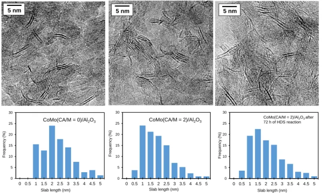
A careful process of measuring the length of the slabs present in each sample was carried out by modifying the contrast to make sure to see the smallest particles. The addition of citric acid leads to a decrease of the average slab length from 2.90 ± 0.12 nm to 1.95 ± 0.10 nm. The length distribution is given in Figure 2.
Figure 2. HR-TEM analysis of slab length distribution: images of CoMo(CA/M=0)/Al2O3, CoMo(CA/M=2)/Al2O3 and CoMo(CA/M=2)/Al2O3 after 72 h of thiophene reaction.
Also an increase of the average stacking number (1.80 ± 0.04 to 2.20 ± 0.05) is noticed. The presence of particles stacked in two or more slabs is significant in both samples, but the amount of the rather small monolayer slabs observed in the CoMo(CA/M=2)/Al2O3 sample was much higher than in the CoMo(CA/M=0)/Al2O3
sample. Such results are in accordance with previously reported results on Mo
0 5 10 15 20 25 30 0 0.5 1 1.5 2 2.5 3 3.5 4 4.5 5 CoMo(CA/M = 0)/Al2O3 Slab length (nm) Freq ue ncy ( %) 0 5 10 15 20 25 30 0 0.5 1 1.5 2 2.5 3 3.5 4 4.5 5 Slab length (nm) Freq ue ncy ( %)
CoMo(CA/M = 2)/Al2O3 after 72 h of HDS reaction 5 nm 5 nm 5 n m 5 nm 5 n m 5 nm 0 5 10 15 20 25 30 0 0.5 1 1.5 2 2.5 3 3.5 4 4.5 5 Slab length (nm) Freq ue ncy ( %) CoMo(CA/M = 2)/Al2O3
12 catalysts and ascribed to the reduced interaction between the (Co)MoS slabs and the support due to the addition of citric acid [17].
3.3 Effect of citric acid addition in the 2D-morphology of CoMo(CA/M=x)/Al2O3 Figure 3 presents the HR STEM-HAADF micrographs of sulfided CoMo(CA/M=0)/Al2O3 (Figure 3A-C) and CoMo(CA/M=2)/Al2O3 (Figure 3D-F)
respectively. As expected for the HAADF mode, the observed particles have a good quality contrast and, therefore, the acquisition parameters used are suitable for revealing the 2D morphology of the slabs in these industrial grade catalysts. On a large field of view, sample CoMo(CA/M=0)/Al2O3 consist of CoMoS slabs that are
distributed over the alumina support in the form of plates. Higher contrast in some zones of both set of images are attributed to an increase of metal density. This is observed more in sample CoMo(CA/M=0)/Al2O3 and is related to agglomerated or
stacked slabs. On the other hand, striking changes are observed for the sample that was prepared in presence of citric acid. The particles observed in the CoMo(CA/M=2)/Al2O3 sample are characterized by their considerable small size
compared to the ones observed in CoMo(CA/M=0)/Al2O3, and in many occasions,
what resembles groups of a few atoms and even individual atoms dispersed all over the support are observed. Such groups and individual atoms were also visible in the images of sulfided CoMo (CA/M=0)/Al2O3 sample but in much lesser extent. The
zoom-in in figure (3-E), puts in evidence a particle with dispersion of 1, this is, all the atoms of the slab are exposed. Their interatomic distances, that are of the order
of 3.1 Å, are in good agreement with the ones expected for Mo-Mo interatomic
13 non-promoted MoS2 prepared as well with and without citric acid as a chelating agent
14 Figure 3. HR STEM-HAADF micrographs of CoMoS particles of CoMo(CA/M=0)/ Al2O3
(A-C) and CoMo(CA/M=2)/Al2O3 (D-F) of different areas. Inset E: zoom in of particle with dispersion degree of 1.0. 2 nm
A)
2 nmD)
2 nmE)
2 nm 2 nmC)
2 nmF)
B)
2 nm 2 nm 1 nm A B C 15 20 25 30 35 40 0 0.2 0.4 0.6 0.8 1 1.2 15 20 25 30 35 40 0 0.2 0.4 0.6 0.8 1 1.2 1.4 1.6 1.8 15 20 25 30 35 40 0 0.2 0.4 0.6 0.8 1 1.2 1.4 A B C Intensity (a. u.) Probe position (nm) 2.70 Å 2.85 Å 2.80 Å Co - Co Mo - Mo Mo - Co 2.85 Å Mo - Mo Mo - Co 2.70 Å15 To better understand the improvement of the dispersion degree, measurements of the length and perimeter were carried out in each one of the samples, and using the Eq. 1, it was found that the addition of citric acid decreases the average length from 2.60 ± 0.50 to 1.32 ± 0.50 nm. The calculated particle dispersion (D) value passes from 48% for CoMo (CA/M=0)/Al2O3 to 78% for CoMo (CA/M=2)/Al2O3. Table 1
gathers together the measured and calculated parameters for each of the analyzed samples. Since the catalytic HDS reaction activity is ascribed to the coordinatively unsaturated sites (CUS) of the slabs, located in the edges of the slab, an increase of dispersion is therefore associated to an increase in activity.
3.4. Observation of CoMo/Al2O3 used catalyst.
Very often TMS catalysts are analyzed after the sulfidation stage, nevertheless, the fact that during the catalytic reaction stage the catalyst is contacted with hydrogen and also with H2S is sometimes overlooked. One question that arises is the stability
of the very small agglomerates observed in particular in the sulfided CoMo (CA/M=2)/Al2O3 catalyst. If we take into account that during the catalytic reaction the
catalyst is in contact with H2 and with H2S present as a byproduct, could there be a
subsequent transformation or reorganization of such agglomerates? To answer this, the sulfided CoMo (CA/M=2)/Al2O3 sample was analyzed after being subjected for
72 hours of catalytic test in order to know if the nanoslabs undergo any alteration. Therefore, this analysis is a way to observe their stability against prolonged reaction conditions. The sulfided CoMo (CA/M=2)/Al2O3 was chosen as used sample since it
16 shows more clusters or individual atoms than the sulfided CoMo (CA/M=0)/Al2O3
sample.
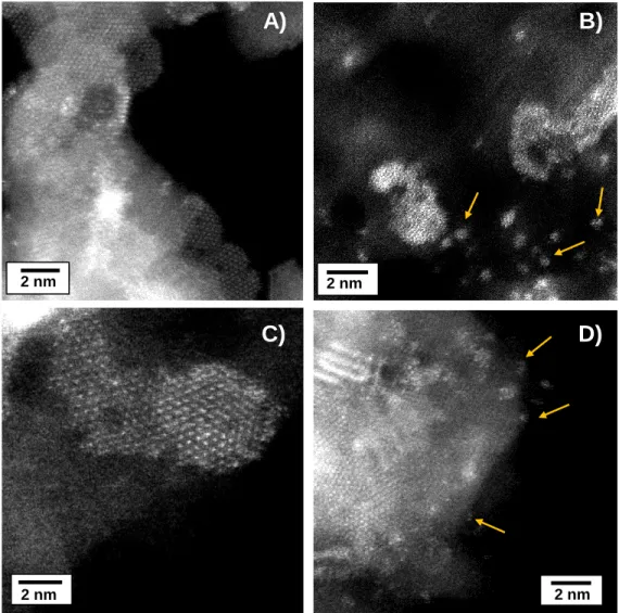
Figure 4. HR STEM-HAADF micrographs of CoMoS particles of CoMo(CA/M=2)/Al2O3 after 72 h of thiophene HDS reaction at 623K. The arrows indicate that the few atoms
agglomerates observed in CoMo(CA/M=2)/Al2O3 after sulfidation are still present.
The STEM-HAADF images of Figure 4(A-D) revealed that no radical change in the shape of the slabs occurs upon HDS reaction. The agglomerates of a few atoms previously observed in the sulfided CoMo(CA/M=2)/Al2O3 catalyst remain Figure
2 nm 2 nm 2 nm 2 nm 2 nm 2 nm
A)
B)
C)
D)
17
4(B and D). These results suggest that the subnanometric particles have a good
stability under reaction conditions.
Figure 5 allows the comparison of the three sulfided promoted samples,
CoMo(CA/M=0)/Al2O3, CoMo(CA/M=2)/Al2O3 and used CoMo(CA/M=2)/Al2O3 after
thiophene HDS reaction, in terms of length distribution and processed STEM-HAADF images. Complementary, Table I give the values of average length and stacking obtained by TEM for the three samples and the average length and dispersion obtained by STEM-HAADF. Comparison between these values confirm the stability of the CoMo(CA/M=2) catalyst under reaction conditions.
Table I. Parameters calculated from the HR TEM and HR STEM-HAADF images for
the γ-Al2O3 supported Catalyst.
Mode Parameters CoMo(CA/M=0) CoMo(CA/M=2)
CoMo(CA/M=2) after 72 h HDS
reaction
TEM Average length (nm) 2.90 ± 0.12 1.95 ± 0.10 1.94 ± 0.12
Stacking 1.80 ± 0.04 2.20 ± 0.05 2.26 ± 0.05
HAADF Average length (nm) 2.60 ± 0.50 1.32 ± 0.50 1.36 ± 0.50
Dispersion (measured) 0.48 ± 0.08 0.78 ± 0.08 0.76 ± 0.08 *Theoretical Dispersion (triangle) 0.58 0.86 0.8 *Theoretical Dispersion (hexagon) 0.43 0.7 0.63
18 Figure 5. Distribution of the measured length and STEM-HAADF images of the particles of
CoMo(CA/M=0)/Al2O3, CoMo(CA/M=2)/Al2O3 and CoMo(CA/M=2)/Al2O3 after thiophene HDS reaction (72h). 0 10 20 30 40 50 0 0.5 1 1.5 2 2.5 3 3.5 4 4.5 5 2 nm 2 nm 0 10 20 30 40 50 0 0.5 1 1.5 2 2.5 3 3.5 4 4.5 5 CoMo(CA/M=0)/Al2O3 2 nm Length (nm) Freq ue nc y (%) Length (nm) Freq ue nc y (%)
A)
B)
CoMo(CA/M=2)/Al2O3 0 5 10 15 20 25 30 35 0 0.5 1 1.5 2 2.5 3 3.5 4 4.5 5 CoMo(CA/M=2)/Al2O3 after 72h Length (nm) Freq ue nc y (%)C)
2 nm19 For the three samples, the mean length value obtained from the HR STEM-HAADF images is lower than the one obtained from the HRTEM ones, underlying that it can be hard to distinguish the smallest particles in HRTEM. Moreover, the length distribution from both techniques also differ: more homogeneous lengths are observed in HR STEM-HAADF than in HRTEM. Similar results were previously reported in [20]. Note that the point to point resolution for STEM-HAADF technique (0.78 Å) is also better than that for HRTEM (1.0 Å).
The dispersion value obtained from the STEM-HAADF slab images is closer to the theoretical dispersion obtained with hexagonal shape in absence of citric acid while with citric acid it tends to be closer to the theoretical dispersion calculated for triangular slabs. Compared to the Mo/Al2O3 sample, it seems that the effect of citric
acid on the slab shape occurs in the opposite direction. Nevertheless, this result could also indicate that these triangular particles are exposing S-edges, i. e. that
citric acid still favors S-edge exposition. Future work along with spectroscopy is
presently being carried out in order to understand better and confirm this hypothesis.
4. Conclusion
HR STEM-HAADF unequivocally demonstrates that adding citric acid in the preparation of CoMo catalysts significantly reduces the size of CoMoS nano-slabs. This result goes hand in hand with the infrared spectra results observed, where the band associated with the active CoMoS sites increases considerably. Numerous agglomerates formed by a few atoms with a high degree of dispersion are detected in the sulfide sample CoMo(CA/M=2)/Al2O3. These clusters are proved to be stable
20 after being subjected to a thiophene HDS reaction for 72 hours in the same way as the nanometric ones. This demonstrates that the catalysts retain their integrity during the catalytic reaction process and therefore that analyzing the catalyst after sulfidation is relevant to understand the catalyst under HDS operational conditions. Next step is to study the variation of atomic contrast in several slabs of CoMo catalysts in order to verify the decoration model as it has been reported recently for NiW catalysts.
Acknowledgements
L. Zavala-Sanchez acknowledges the Mexican National Council for Science and Technology (CONACYT) for the Ph. D. grant. The authors acknowledge LABEX EMC3 for the financial support to MIMOSA project.
5. References
[1] Sulfur production report by the United States Geological Survey, No Title, Minerals.Usgs.Gov. (2017).
[2] EIA, Annual Energy Outlook 2019 with projections to 2050, USA, 2019. www.eia.gov/aeo.
[3] T. Alphazan, A. Bonduelle-Skrzypczak, L. Legens, A.-S. Gay, Z. Boudene, M. Girleanu, O. Ersen, C. Cope, P. Raybaud, Highly Active Nonpromoted Hydrotreating Catalysts through the Controlled Growth of a Supported Hexagonal WS2 Phase, ACS Catal. 4 (2014) 42. doi:10.1021/cs501311m.
[4] H. Topsøe, B.S.. Clausen, F.E.. Massoth, Catalysis Science and Technology, Springer, Berlin, 1996. doi:10.1007/978-3-642-61040-0_1.
[5] S. Topsøe, H., Clausen, B. S., Candia, R., Wivel, C., & Mørup, In Situ Mössbauer Emission Spectroscopy Studies of Unsupported and Supported Sulfided Co-Mo Hydrodesulfurization Catalysts: Evidence for and Nature of a Co-Mo-S Phase, J.
21 Catal. 68 (1981) 433–452. doi:10.1016/0021-9517(81)90114-7.
[6] F. Besenbacher, M. Brorson, B.S. Clausen, S. Helveg, B. Hinnemann, J. Kibsgaard, J. V. Lauritsen, P.G. Moses, J.K. Nørskov, H. Topsøe, Recent STM, DFT and HAADF-STEM studies of sulfide-based hydrotreating catalysts: Insight into mechanistic, structural and particle size effects, Catal. Today. 130 (2008) 86–96. doi:10.1016/j.cattod.2007.08.009.
[7] H. Topsøe, B.S. Clausen, Importance of Co-Mo- S Type Structures in Hydrodesulfurization, Catal. Rev. Sci. Eng. 26 (1984) 395–420. doi:10.1080/01614948408064719.
[8] L.S. Byskov, J.K. Nørskov, B.S. Clausen, H. Topsøe, Edge termination of MoS2 and CoMoS catalyst particles, Catal. Letters. 64 (2000) 95–99. doi:10.1023/A:1019063709813.
[9] B. Baubet, M. Girleanu, A.S. Gay, A.L. Taleb, M. Moreaud, F. Wahl, V. Delattre, E. Devers, A. Hugon, O. Ersen, P. Afanasiev, P. Raybaud, Quantitative Two-Dimensional (2D) Morphology-Selectivity Relationship of CoMoS Nanolayers: A Combined High-Resolution High-Angle Annular Dark Field Scanning Transmission Electron Microscopy (HR HAADF-STEM) and Density Functional Theory (DFT) Study, ACS Catal. 6 (2016) 1081–1092. doi:10.1021/acscatal.5b02628.
[10] E. Krebs, B. Silvi, P. Raybaud, Mixed sites and promoter segregation: A DFT study of the manifestation of Le Chatelier’s principle for the Co(Ni)MoS active phase in reaction conditions, Catal. Today. (2008) 160–169. doi:10.1016/j.cattod.2007.06.081. [11] J. Chen, F. Maugé, J. El Fallah, L. Oliviero, IR spectroscopy evidence of MoS2 morphology change by citric acid addition on MoS2/Al2O3 catalysts – A step forward to differentiate the reactivity of M-edge and S-edge, J. Catal. 320 (2014) 170–179. doi:10.1016/j.jcat.2014.10.005.
[12] J. Chen, L. Oliviero, X. Portier, F. Maugé, On the morphology of MoS 2 slabs on MoS 2 /Al 2 O 3 catalysts: the influence of Mo loading, RSC Adv. 5 (2015) 81038–81044. doi:10.1039/C5RA14768A.
[13] A. Travert, C. Dujardin, F. Maugé, S. Cristol, J.F. Paul, E. Payen, D. Bougeard, Parallel between infrared characterisation and ab initio calculations of CO adsorption on sulphided Mo catalysts, Catal. Today. 70 (2001) 255–269.
[14] M. Girleanu, S. Lopes Silva, D. Ihiawakrim, A. Chaumonnot, A. Bonduelle-Skrzypczak, F. Lefebvre, V. Dufaud, A.S. Gay, O. Ersen, HAADF-STEM high-resolution study of nanometric MoS2 inside mesoporous SBA-15, Microporous
22 Mesoporous Mater. 217 (2015) 190–195. doi:10.1016/j.micromeso.2015.06.021. [15] S.J. Nellist, P. D., & Pennycook, Direct Imaging of the Atomic Configuration of
Ultradispersed Catalysts, Science (80-. ). 274 (1996) 413–415. doi: 10.1126/science.274.5286.413%0AArticle.
[16] K. Al-Dalama, A. Stanislaus, A Comparative Study of the Influence of Chelating Agents on the Hydrodesulfurization (HDS) Activity of Alumina and Silica-Alumina-Supported CoMo Catalysts, Energy and Fuels. 20 (2006) 1777–1783. doi:10.1021/ef060125a.
[17] R. Cattaneo, T. Shido, R. Prins, The Relationship between the Structure of NiMo/SiO2 Catalyst Precursors Prepared in the Presence of Chelating Ligands and the Hydrodesulfurization Activity of the Final Sulfided Catalysts, J. Catal. 185 (1999) 199– 212. doi:10.1006/JCAT.1999.2492.
[18] S. Badoga, K.C. Mouli, K.K. Soni, A.K. Dalai, J. Adjaye, Beneficial influence of EDTA on the structure and catalytic properties of sulfided NiMo/SBA-15 catalysts for hydrotreating of light gas oil, Appl. Catal. B Environ. 125 (2012) 67–84. doi:10.1016/j.apcatb.2012.05.015.
[19] J. Chen, J. Mi, K. Li, X. Wang, E. Dominguez Garcia, Y. Cao, L. Jiang, L. Oliviero, F. Oise, Role of Citric Acid in Preparing Highly Active CoMo/Al 2 O 3 Catalyst: From Aqueous Impregnation Solution to Active Site Formation, Ind. Eng. Chem. Res. 56 (2017) 14172–14181. doi:10.1021/acs.iecr.7b02877.
[20] L. Zavala-Sanchez, X. Portier, F. Maugé, L. Oliviero, High-resolution STEM-HAADF microscopy on a γ-Al2O3 supported MoS2 catalyst-proof of the changes in dispersion and morphology of the slabs with the addition of citric acid, Nanotechnology. 31 (2019) 035706. doi:10.1088/1361-6528/ab483c.
[21] E. Dominguez Garcia, J. Chen, E. Oliviero, L. Oliviero, F. Maugé, New insight into the support effect on HDS catalysts: evidence for the role of Mo-support interaction on the MoS 2 slab morphology, Appl. Catal. B Environ. (2020) 117975. doi:10.1016/j.apcatb.2019.117975.
[22] J. Chen, L. Oliviero, X. Portier, F. Mau, On the morphology of MoS 2 slabs on MoS 2 /Al 2 O 3 catalysts: the influence of Mo loading, RSC. 5 (2015) 81038–81044. doi:10.1039/c5ra14768a.
[23] A. Travert, C. Dujardin, F. Maugé, E. Veilly, S. Cristol, J.-F. Paul, E. Payen, CO Adsorption on CoMo and NiMo Sulfide Catalysts: A Combined IR and DFT Study, Phys. Chem. B. 110 (2006) 1261–1270. doi:10.1021/jp0536549.
23 [24] F. Maugé, J.C. Lavalley, FT-IR Study of CO Adsorption on Sulfided Mo/Al2O3 Unpromoted or Promoted by Metal Carbonyls: Titration of Sites, J. Catal. 137 (1992) 69–76. doi:10.1016/0021-9517(92)90139-9.
[25] E.D. Garcia, Effet du support sur la morphologie et l’activité des catalyseurs d’hydrodésulfuration, Université de Caen, 2017.
[26] M.A. Lélias, E. Le Guludec, L. Mariey, J. Van Gestel, A. Travert, L. Oliviero, F. Maugé, Effect of EDTA addition on the structure and activity of the active phase of cobalt-molybdenum sulfide hydrotreatment catalysts, Catal. Today. 150 (2010) 179–185. doi:10.1016/j.cattod.2009.07.107.
[27] M.A. Lélias, J. van Gestel, F. Maugé, J.A.R. van Veen, Effect of NTA addition on the formation, structure and activity of the active phase of cobalt–molybdenum sulfide hydrotreating catalysts, Catal. Today. 130 (2008) 109–116. doi:10.1016/J.CATTOD.2007.07.018.
[28] M.A. Lélias, P.J. Kooyman, L. Mariey, L. Oliviero, A. Travert, J. Van Gestel, J.A.R. Van Veen, F. Maugé, Effect of NTA addition on the structure and activity of the active phase of cobalt-molybdenum sulfide hydrotreating catalysts, (2009). doi:10.1016/j.jcat.2009.07.006.
[29] F.L. Deepak, R. Esparza, B. Borges, X. Lopez-Lozano, M. Jose-Yacaman, Direct Imaging and Identification of Individual Dopant Atoms in MoS2 and WS2 Catalysts by Aberration Corrected Scanning Transmission Electron Microscopy, ACS Catal. 1 (2011) 537–543. doi:10.1021/cs100141p.
[30] S. Kasztelan, J. Grimblot, J.P. Bonnelle, E. Payew, H. Toulhoat, Y. Jacquin+, Preparation of Co-Mo-γAl2O3 and Ni-Mo-γAl2O3 catalysts by pH regulation of molybdenum solution. characterization of supported species and hydrogenation activities, Appl. Catal. 7 (1983) 91–112. doi:0.1016/0166-9834(83)80241-3.
[31] M. Nikulshina, A. Mozhaev, C. Lancelot, M. Marinova, P. Blanchard, E. Payen, C. Lamonier, P. Nikulshin, MoW synergetic effect supported by HAADF for alumina based catalysts prepared from mixed SiMonW12-n heteropolyacids, Appl. Catal. B Environ. 224 (2018) 951–959. doi:10.1016/j.apcatb.2017.11.049.


![[PDF] Introduction aux systemes de gestion de bases de donnees avec SQL Server | Cours informatique](data:image/gif;base64,R0lGODlhAQABAIAAAP///wAAACH5BAEAAAAALAAAAAABAAEAAAICRAEAOw==)