by Alec Robertson
Bachelor of Engineering in Mechanical Engineering Monash University, 1996
Bachelor of Science in Computer Science and Applied Mathematics Monash University, 1994
Melbourne, Australia
Submitted to the Department of Mechanical Engineering in Partial Fulfillment of the Requirements for the Degree of
Master of Science in Mechanical Engineering at the
Massachusetts Institute of Technology May 2003
© 2003 Massachusetts Institute of Technology All Rights Reserved
Signature of Author ...
Certified by ...
Deartment of Mechanical Engineering May 9, 2002
Alexander H. Slocum Pro Mechanical Engineering Thesis Supervisor Accepted by ...
Ain A. Sonin Chairman, Department Committee on Graduate Students MASSACHUSETTS INSI
OF TECHNOLOGY
JUL
ARI0LIBRARIES TITUTE
by
ALEC ROBERTSON
Submitted to the Department of Mechanical Engineering on May 9, 2003 in Partial Fulfillment of the Requirements for the Degree of Masters of Science in
Mechanical Engineering
Abstract
A fundamental limit associated with current industrial robots is their accuracy. Parallel robots offer many benefits compared to serial robots due to their superior accuracy and stiffness. Amongst the most important components in these robots are the three degree of freedom bearings connecting the robot's parallel arms. Spherical joints have been devel-oped based on a ball and socket configuration, preloaded by rings of magnets arrayed about the socket. Four prototypes have been implemented based on point, rolling, sliding and fluid contact mechanisms and a spherical-kinematic test mechanism has been con-structed to automate the measurement of joint accuracy.
The average error for the joint prototypes is found to be 4 micrometers and the maximum error is 12 micrometers; which can be reduced to 8 micrometers through calibration. The maximum preload force is found to be approximately 1OON, rendering these joints suitable for high accuracy non-contact applications, such as in-line measurement and inspection.
Thesis Supervisor: Professor Alexander H. Slocum
Professor of Mechanical Engineering
Funding for this research was provided by ABB Corporate Research, under the guidance of Professor Torgny Brogirdh and Dr. ZhongXue Gan. I would like to thank both Torgny and Gan for their help throughout the Masters thesis. Thanks must also go to my advisor Professor Alexander Slocum and to my MIT colleagues who helped along the way, in par-ticular Adam Rzepniewski, who worked with me during the initial design phase and Charles Dumont, who helped develop the advanced modeling algorithms. Finally, I would like to thank my family and friends for their support and feedback throughout the thesis.
TABLE OF CONTENTS
ACKNOWLEDGEMENTS TABLE OF CONTENTS LIST OF FIGURES ... LIST OF TABLES ... NOMENCLATURE .... . . . 5 . . . . . . . . 7 . . . . . 11 15 17 CHAPTER 1. INTRODUCTION . . 1.1 M otivation . . . . 1.2 Parallel Robot Overview 1.3 Parallel Robot Joints . .1.4 Joint Survey . . . . 1.5 Functional Requirements 1.5.1 Spherical motion 1.5.2 Contact Type . . . 1.5.3 Preload . . . . 1.6 Conclusion . . . .
CHAPTER 2. DESIGN PROCESS . 2.1 Overview . . . . 2.2 Joint Design . . . . 2.2.1 Strategy Phase 2.2.2 Concept Phase 2.2.3 Module Phase 2.2.4 Manufacture . . . 2.3 Test Rig Design . . . . .
2.3.1 Strategy Phase 2.3.2 Concept Phase 2.3.3 Module Phase 2.3.4 Manufacture . . . 2.4 Conclusion . . . . . . . . 1 9 . . . . 19 . . . . 2 0 . . . . 2 2 . . . . 2 4 . . . . 2 6 . . . . 2 6 . . . . 2 8 . . . . 2 8 . . . . 3 0 33 33 35 35 39 45 48 53 53 55 59 61 . 63
3.1 Overview . . . . 3.2 Preload Analysis . . . . 3.2.1 Magnet Characterization . . . . 3.2.2 Sliding and Fluid Contact Prototypes 3.2.3 Point and Rolling Contact Prototypes 3.3 Accuracy Analysis . . . . .
3.3.1 Sphere Fit Model . . . 3.3.2 Kinematic Model . . . 3.4 Thermal Analysis . . . . 3.5 Contact Analysis . . . . 3.6 Preload Measurement . . . . 3.7 Measurement and Calibration
3.7.1 Rolling Contact Joint 3.7.2 Point Contact Joint . . 3.7.3 Sliding Contact Joint 3.7.4 Joint Comparison . 3.8 Conclusions . . . .
CHAPTER 4. FLUID CONTACT JOINT
4.1 Overview . . . .
4.2 Analysis ...
4.2.1 Fluid Flow Analysis 4.2.2 Preload Analysis . .
4.2.3 Stiffness Analysis .
4.3 Manufacture . . . . 4.4 Measurement . . . .
4.4.1 Fluid Flow Measurement 4.4.2 Stiffness Measurement 4.4.3 Accuracy Measurement 4.4.4 Joint Comparison . .
4.5 Conclusions . . . .
CHAPTER 5. ADVANCED MODELING
5.1 Overview . . . . . . . . 9 3 . . . . 9 3 . . . . 9 4 . . . . 9 4 . . . 1 0 1 . . . 1 0 3 . . . 1 0 7 . . . 1 0 8 . . . 1 0 8 . . . 1 1 0 . . . 1 1 6 . . . 1 1 7 . . . 1 1 9 . . . . 121 . . . 121 5.2 Genetic Programming Based Model Improvement
65 68 68 68 72 73 73 74 81 82 84 85 85 88 89 90 91 . . . .122
5.2.1 Introduction . . . 122
5.2.2 Implementation . . . 124
5.2.3 Results and Analysis . . . 128
5.2.4 Framework . . . 133
5.3 Spherical Joint Models . . . 135
5.4 Conclusions . . . 139
CHAPTER 6. CONCLUSIONS ... ... 141
LIST OF FIGURES
Figure 1.1 Figure 1.2 Figure 1.3 Figure 1.4 Figure 1.5 Figure 1.6 Figure 1.7 Figure 1.8 Figure 1.9 Figure 1.10 Figure 1.11 Figure 1.12 Figure 2.1 Figure 2.2 Figure 2.3 Figure 2.4 Figure 2.5 Figure 2.6 Figure 2.7 Figure 2.8 Figure 2.9 Figure 2.10 Figure 2.11 Figure 2.12 Figure 2.13 Figure 2.14 Figure 2.15 Figure 2.16Delta robot configuration
ABB IRB340 robot . . . . Tau robot configuration... Tau measurement prototype . . . Three degree of freedom spherical Delta robot joint pair . . . . Tau robot prototype . . . . Modified universal joint...
Automotive rod end . . . . Ball bar mechanisms . . . . Flat pad air bearing . . . . Spherical joint . . . . Modified universal joint...
Magnetic air bearing . . . . Flexure joint . . . . Slot and ball . . . . Spring preload . . . . Double cup . . . . Sliding arm universal joint . . . Modified universal joint... Kinematic chain . . . . Porous carbon air . . . . Magnetic cup . . . . Sealed spring . . . . Spherical motion concept tree . . Sliding contact assembly model Sliding contact exploded model Rolling contact assembly model
. . . . 2 0
joint
Figure 2.18 Figure 2.19 Figure 2.20 Figure 2.21 Figure 2.22 Figure 2.23 Figure 2.24 Figure 2.25 Figure 2.26 Figure 2.27 Figure 2.28 Figure 2.29 Figure 2.30 Figure 2.31 Figure 3.1 Figure 3.2 Figure 3.3 Figure 3.4 Figure 3.5 Figure 3.6 Figure 3.7 Figure 3.8 Figure 3.9 Figure 3.10 Figure 3.11 Figure 3.12 Figure 3.13 Figure 3.14 Figure 3.15 Figure 3.16
Sliding contact socket . . . . Sliding contact socket . . . . Sliding contact joint . . . . Point contact . . . . Rolling contact . . . . Rolling contact joint . . . . Double ball bar . . . . Universal mechanism . . . . Actuated clamp . . . . Test rig base . . . . Test rig complete mechanism . . OMAX waterjet path. . . . . Spherical kinematic test rig . . . Test rig and CMM probe . . . . Rolling contact . . . . Point contact . . . . Sliding contact . . . . Test rig . . . . Generic spherical joint schematic Force balance for socket fixed mo Socket fixed configuration . . . Ball fixed configuration . . . . .
. . . . . . . . . . . . . . . . . . . . . . . . unting . . . . . . . . . . . . Preload characteristics for sliding and fluid contact joints Sliding and fluid contact force distribution . . . . Preload characteristics for point and rolling contact joint Spherical joint sphere fit model . . . . Spherical joint structural loop . . . . Spherical joint nominal kinematic model . . . . Singular value decomposition . . . . Calibration algorithm . . . . 49 49 49 50 50 50 53 53 53 61 61 62 62 62 66 66 66 66 68 69 70 70 70 71 72 73 74 75 75 77
Figure 3.17 Figure 3.18 Figure 3.19 Figure 3.20 Figure 3.21 Figure 3.22 Figure 3.23 Figure 3.24 Figure 3.25 Figure 3.26 Figure 3.27 Figure 3.28 Figure 3.29 Figure 3.30 Figure 4.1 Figure 4.2 Figure 4.3 Figure 4.4 Figure 4.5 Figure 4.6 Figure 4.7 Figure 4.8 Figure 4.9 Figure 4.10 Figure 4.11 Figure 4.12 Figure 4.13 Figure 4.14 Figure 4.15 Figure 4.16 Figure 4.17
Error model inverse kinematics . . . . Error budget repeatability . . . . Error budget accuracy . . . . Thermal expansion of joint socket . . . . Contact mechanics for point and rolling contact joints . . . . . Deformation between two spheres . . . . Hertz contact deformation coefficients . . . . Measurement of magnet force . . . . Measured and predicted preload forces . . . . Accuracy distribution of rolling contact prototype . . . . Accuracy distribution of point contact prototype . . . . Accuracy distribution of sliding contact prototype . . . .
Maximum and mean residual errors for joint prototypes . . . . Predicted and measured preload forces . . . . Fluid contact joint prior to replication . . . . Polar coordinates and corresponding area and volume elements Fluid contact joint schematic . . . . Navier Stokes equations in cylindrical coordinates . . . . Flow assumptions . . . . Reduced Navier Stokes equations . . . . Flow profile for radial axis equation . . . . Volume flow rate . . . . Pressure drop and resistance profiles . . . .
Equivalent socket dimensions in cylindrical coordinates . . . . Inlet pressure . . . . Stiffness formulation . . . . Design flowchart for air bearing joint . . . . Magnet, air gap and contact stiffness regimes . . . . Force-displacement schematic for fluid contact joint . . . . Magnet regime stiffness model . . . . Fluid regime linearized stiffness model . . . .
. . . . 78 . . . . 79 . . . . 79 . . . . 81 . . . . 82 . . . . 82 . . . . 83 . . . . 84 . . . . 84 . . . . 87 . . . . 88 . . . . 89 . . . . 90 . . . . 90 . . . . 93 . . . . 94 . . . . 95 . . . . 95 . . . . 96 . . . . 96 . . . . 97 . . . . 97 . . . . 98 . . . . 98 . . . . 99 . . . . 100 . . . . 102 . . . . 103 . . . . 104 . . . . 104 . . . . 105
Figure 4.19 Figure 4.20 Figure 4.21 Figure 4.22 Figure 4.23 Figure 4.24 Figure 4.25 Figure 4.26 Figure 4.27 Figure 4.28 Figure 4.29 Figure 4.30 Figure 4.31 Figure 5.1 Figure 5.2 Figure 5.3 Figure 5.4 Figure 5.5 Figure 5.6 Figure 5.7 Figure 5.8 Figure 5.9 Figure 5.10 Figure 5.11 Figure 5.12 Figure 5.13 Figure 5.14 Figure 5.15 Figure 5.16
Replication material stiffness model . . . 105
Brass orifice housing stiffness model . . . 106
Air bearing chassis with pneumatic connectors . . . 107
Vertical displacement as a function of inlet pressure . . . 108
Predicted air gap as a function of inlet pressure . . . 109
Texture analyzer mounted with socket and ball . . . 110
Force-displacement characteristics with encoder displacement data . . 111
Extensometer force-displacement characteristics for tension cycle . . . 112
Contact region force-displacement characteristics . . . . Fluid region force-displacement characteristics . . . . Force-displacement characteristics for air and no air . . . Fluid contact joint residual error distribution . . . . Maximum and mean residual errors for joint prototypes Predicted and measured preload forces . . . . ABB IRB6400R Industrial Robot . . . . Compensator model . . . . Cross over and mutation for linear sequence . . . . Linear sequence and equations . . . . Fitness function . . . . Binary tree crossover . . . . Fitness vs. generation . . . . Extrapolation of linear sequence . . . . Histogram of referenced inputs for standard model . . . . Linear sequence compensation and equation . . . . Comparison of calibration models . . . . Histogram of referenced inputs for improved model . . . Histogram of referenced inputs for spherical joint . . . . Linear sequence compensation for spherical joint . . . . Relationship between error parameters and axis 1 motion Accuracy distribution for improved joint model . . . . . . . . 113 . . . 113 . . . 115 . . . 116 . . . 117 . . . 117 . . . 121 . . . 124 . . . 126 . . . 126 . . . 127 . . . 128 . . . 129 . . . 129 . . . 130 . . . 131 . . . 132 . . . 133 . . . 135 . . . 135 . . . 136 . . . 138
LIST OF TABLES
TABLE 1.1 TABLE 1.2 TABLE 2.1 TABLE 2.2 TABLE 2.3 TABLE 2.4 TABLE 2.5 TABLE 2.6 TABLE 2.7 TABLE 2.8 TABLE 2.9 TABLE 2.10 TABLE 2.11 TABLE 2.12 TABLE 2.13 TABLE 3.1 TABLE 3.2 TABLE 3.3 TABLE 3.4 TABLE 3.5 TABLE 4.1 TABLE 4.2 TABLE 4.3 TABLE 5.1 TABLE 5.2 Functional specifications ... 26Preliminary functional requirements . . . . 29
Joint strategy table . . . . 38
Spherical motion concepts . . . . 39
Contact type concepts . . . . 40
Preload concepts . . . . 41
Joint design concepts . . . . 42
Concept evaluation chart . . . . 44
Sliding and fluid contact joint generations . . . . 45
Point and rolling contact joint generations . . . . 47
Test rig strategies . . . . 54
Test rig concepts . . . . 55
Test rig concepts for accuracy measurement . . . . 56
Concept evaluation chart . . . . 58
Test rig design generations . . . . 59
Preload optimization for sliding contact joint . . . . 71
Reduced calibration model parameters . . . . 76
Hertz contact deformation spreadsheet . . . . 83
Comparison of calibration methods . . . . 86
Kinematic calibration . . . . 87
Preload design guide for fluid bearing joint . . . 101
Fluid flow design guide for fluid contact joint . . . 102
Stiffness coefficients for fluid and contact regimes . . . 114
Mathematical operators and input registers . . . 125
UPPER CASE:
F Force [N]. Forward kinematics function [m]
X Position vector [in]
M Measurement position vector [m]
E Error position vector. Elastic modulus [Pa]
J Jacobian matrix
U Left eigenmatrix
V Right eigenmatrix
S Singular value matrix
L Length [m] T Temperature [0C] V Volume [in3] A Area [m2] R Resistance [Palm3] P Pressure [Pa]
Q
Flow rate [in3/s] K Stiffness [N/m] LOWER CASE: r Radius [m] I Length [in] u Velocity [m/s] x Position [m] y Position [m] z Position [m]h Air gap [in]
Angle [rad] Angle [rad] Angle [rad]
Angle [rad]. Coefficient [-]
Error parameter vector. Angle [rad] Displacement [m]
Coefficient of thermal expansion [m/lC] Hertz contact coefficient [-]
Poisson's ratio [-] Viscosity [Ns/m2I Conversion factor [-] Coefficient [-] GREEK: 0 ()T V g 1 17
INTRODUCTION
1.1 Motivation
A fundamental limit associated with current industrial robots is their accuracy. Typically, special machines are used in applications such as measurement, high precision manufac-turing, machining and assembly. However, there is a growing demand from industry to introduce more flexible production methods for these high precision applications and thus new robot concepts and robot components are required. Robot manufacturers are under-taking an investigation into a new family of parallel arm robots to fulfill these demands for higher accuracy. Amongst the most important components in these robots are the bearings, especially for the two or three degree of freedom (DOF) joints connecting the robot's par-allel arms. It is therefore very important to build up a bearing technology expertise to be able to optimize bearings and bearing concepts to the different demands on parallel arm robots for different applications. The bearing technology consists of both bearing kinemat-ics and material science. Examples of kinematkinemat-ics are revolute, universal and ball and socket joints and examples of materials are steel, aluminum, ceramics and plastics. Ball and socket bearings offer high accuracy and a large singularity free workspace, however one significant problem with these bearings is friction between two surfaces while sliding relative to one another. One possibility to reduce the friction significantly while simulta-neously increasing the accuracy is to use aerostatic bearings.
1.2 Parallel Robot Overview
A common parallel robot form is the delta structure [Clavel, 1989] which is shown in Figure 1.1. This robot comprises three sets of two links which intersect at a triangular end-effector plate such that each pair connects to the midpoint of each side of the plate. This provides six connection points, which fully constrains the motion of the end-effector. The necessary degrees of freedom are provided by three rotary actuators connected to the upper ends of the arm pairs, constraining all rotations of the triangular plate and allowing three translational degrees of freedom. This structure is referred to as a 2-2-2 configura-tion to describe the connecconfigura-tion of the arms to the plate. The ABB IRB340 robot, Figure 1.2, is an example of a Delta implementation which is typically used for high speed
pick and place applications.
IRB 34 0 Industral obo AMKOM
A
Aelta
F
2 0B
B
Figure 1.1 Delta robot configuration Figure 1.2 ABB IRB340 robot
The Delta robot configuration is advantageous due to its simplicity and symmetry, which provides for consistent performance and high stiffness throughout the majority of the workspace. However, the workspace to robot volume ratio is low, as is typical of many parallel manipulators; furthermore, the configuration and stiffness degenerates as the apex angle (OA) of the end-effector triangle decreases. If the angle decreases to zero, making the
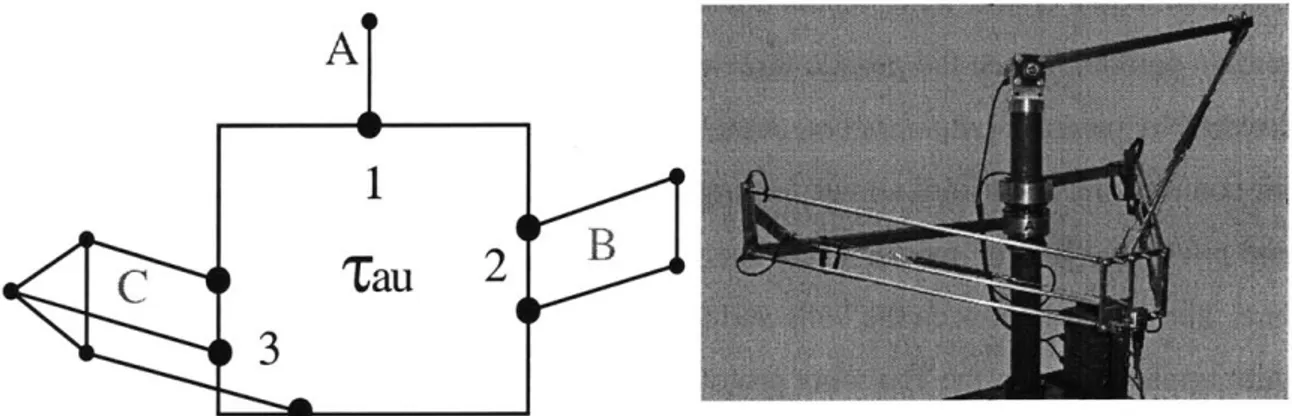
connection between two arms pairs parallel, then the structure inherits an extra degree of freedom and is no longer fully constrained. In order to improve the workspace to robot volume ratio and allow for a greater flexibility in placement of the arms, the Tau configu-ration was developed [Brogbrdh, 1997] and [Brogordh et al, 1998]. The basic Tau config-uration modifies the Delta structure by constraining the arms in a 3-2-1 configconfig-uration as shown in Figure 1.3. This structure allows for arm sets to be mounted in parallel, thus pro-viding a greater scope for possible configurations. The structure is no longer axisymmet-ric, however, which introduces deviations in performance and stiffness dependent on the location in the workspace and the design of the robot structure. The measurement robot prototype (Figure 1.4) mounts the single arm in the vertical plane with the double and tri-ple arm sets mounted in the horizontal plane. The robot can rotate fully about the central post, allowing for a large workspace to robot volume ratio while maintaining consistent performance and stiffness throughout the workspace.
A
1
C
Tau
2
3
1.3 Parallel Robot Joints
The Delta and Tau configurations constrain rotations in all three axes (roll, pitch and yaw) and allow translation in all three axes (x, y and z). The connection between the arms and the end-effector plate must therefore consist of three degree of freedom joints, and the connection between the rotary actuators and the arms should be two degree of freedom (universal) joints. It is also possible to connect the actuators to the arms via three degree of freedom joints, however this allows the lower arms to rotate freely about their own longi-tudinal axis, which does not affect the motion of the end-effector. An idealized three degree of freedom joint is shown in Figure 1.5. This joint comprises a ball seated in a hemispherical socket; the socket is attached to the ball by some preload mechanism, such as a spring, magnetic force or negative pressure (suction). This type of joint is typically referred to as a spherical joint as all three rotary axes (roll, pitch and yaw) intersect at the center of the ball. The IRB340 Delta robot configuration allows for a simplification and modularization of the joint connections. The configuration requires that each arm pair remain parallel, hence the pseudo three degree of freedom joint shown in Figure 1.6, and covered by patent [Hvittfeldt et al, 2002], can be used for both the actuator and end-effec-tor connections. This joint allows for large motion in the two key degrees of freedom (roll and pitch) and limited motion about the yaw axis, thus fully constraining the robot struc-ture. The preload between the balls and the spherical sockets is provided by a spring. The joint implemented in the Tau robot prototype uses a combination of standard and modified universal joints (Figure 1.7 and Figure 1.8). Standard universal joints provide roll and pitch degrees of freedom and connect the actuators to the arms. Modified universal joints are mounted between the arms and the end-effector plate and are implemented by intro-ducing a third degree of freedom in the form of a radial ball bearing in one of the shafts. Such joints represent a minor modification on existing technology and can be manufac-tured with high accuracy and stiffness. However, in the presence of errors, the axes of rotation no longer intersect at a common location, leading to a degeneration in the overall robot accuracy.
In order to improve the accuracy of the Tau robot prototype, a three degree of freedom joint is required which has a large angular working range; high accuracy and stiffness; and
is cost effective.
Figure 1.5 Three degree of freedom spherical joint Figure 1.6 Delta robot joint pair
A*
r~ -.-*-*
Figure 1.7 Tau robot prototype
II J
1.4 Joint Survey
Three degree of freedom joints with a limited working range, commonly referred to as "rod ends", are used extensively in automotive applications where they form the link between the steering rack and the wheel assembly (Figure 1.9). The spherical joints allow for a 30' angular displacement to account for misalignment errors during manufacturing and changes in orientation during operation of the vehicle. However, the angular range of rod end joints is insufficient for the robotics application, which requires an angular work-space on the order of 1800. In order to achieve a large angular range, the field of coordi-nate measurement machines typically use a ball bar apparatus [Bryan, 1992] to calibrate the geometric errors of the machine. These joints are very accurate, display an angular workspace of the order of 1800, and typically consist of a large steel or ceramic ball kine-matically located on three points within a socket (Figure 1.10). The preload between the ball and socket is commonly provided by the weight of the ball bar itself, or using small magnets mounted in the socket. These joints, however, are designed for low load operation and can not tolerate large forces between the ball and the socket.
Figure 1.9 Automotive rod end Figure 1.10 Ball bar mechanisms
A fundamental problem with the three degree of freedom spherical joints used in the Delta robot configuration is the friction between the ball and socket. This is reduced through the use of a teflon coating within the socket and a ceramic ball. An alternate approach to
fric-tion minimizafric-tion is to introduce a high pressure film of air in between the ball and socket such as is used in air bearing applications. Typical air bearings designs are based on flat pads (Figure 1.11), with porous graphite or orifice based air intake mechanisms, however spherical rod ends have also been manufactured for high accuracy alignment of shafts spinning at high angular velocity.
Alternative mechanism approaches have been implemented, in order to achieve a large singularity free workspace. The double slotted spherical joint [Bieg, 1999], refer to Figure 1.12, comprises three concentric housings to achieve a singularity free workspace
cone of 270'. Whereas this exceeds the required 1800, the complexity of such a mecha-nism would result in kinematic inaccuracy.
1.5 Functional Requirements
The goal of the project is to design and construct a three degree of freedom joint, and determine the accuracy and stiffness of the joint throughout its workspace. These goals give rise to numerous functional requirements, which can be divided into three key cate-gories; spherical motion; type of contact between surfaces; and the preload force required to prevent the joint from separating under operating loads.
TABLE 1.1 Functional specifications
Category Functional Specifications
Spherical Motion Workspace Restrictions Singularities Elegance Joint type Scaleable Accuracy Maintenance
Modeling Modularity Calibration
Contact Type Contact Type Lubrication Materials Temperature Weight Sealing
Preload Preload Stiffness
Load capacity Energy usage
I Safety Robustness
1.5.1 Spherical motion
- Workspace. The joint should be capable of transcribing a hemispherical workspace, with an angular range of 1800. The deviation in position from an ideal sphere, at any point in the working range, represents the joint accuracy. - Singularities. There should be no singularities within the required joint
workspace.
- Joint type. The kinematic structure of the joint can be described as a chain of multi degree of freedom mechanisms. In order to achieve three degrees of freedom, the possibilities are 1+1+1 chains; 2+1 chains; and 3 chains. The 1+1+1 chain represents a robot-like chain of three orthogonal rotary joints. Whereas this represents a simple structure, it contains singularities within the workspace which are detrimental to performance. The 2+1 chain repre-sents the modified universal joint structure, which contains no singularities, however does introduce kinematic inaccuracy as the third axis is offset from the other two. The 3 chain represents a pure spherical joint where all three
axes intersect at the same location. This structure promises the highest accu-racy, however the design is more complex than the alternative approaches. - Accuracy and repeatability. The accuracy of the joint should be of the order
of several micrometers and the repeatability should be of the order of a frac-tion of a micrometer. High accuracy ensures that the joint does not signifi-cantly contribute to the inaccuracy of the robot structure. High repeatability ensures that the joint is not perturbed by stochastic effects such as friction and hysteresis, improving the controllability of the overall structure.
- Modeling. The joint should be described by a simple model, such that it may be integrated into an existing modeling framework without inconsistencies between models. All models should be capable of implementation in a real time system.
* Calibration. It should be possible to measure each joint individually, and then integrate the error parameters into the overall robot structure. Alterna-tively, it should be possible to calibrate the joint error parameters as a part of the robot structure. This requires the calibration model to be consistent with the existing robot calibration model and measurement techniques.
e Restrictions. No restrictions should be imposed on the robot design.
Addi-tionally, implementation of the joint in the robot structure should be opti-mized for the operating requirements.
- Elegance. The joint aesthetic should be consistent with the existing robot product range.
- Scalable. It should be possible to use the same joint concept for a range of robot sizes, from small pick and place robots similar to the delta robot, to larger machining centers.
- Maintenance. A minimal amount of maintenance should be required, com-mensurate with the techniques available for existing robots. The existing delta robot joints require no lubrication due to the teflon coating and are typ-ically maintained only following a crash or similar damaging incident. - Modular. A typical parallel robot requires twelve three degree of freedom
joints, ideally a single joint structure can be used. Additionally, the compo-nents required for the joint should be readily available, and the part count
1.5.2 Contact Type
- Contact Type. The connection between contacting members in the joint should be chosen so as to minimize the maintenance required during con-stant operation of the entire robot structure. Furthermore, friction should be minimized to improve working efficiency.
- Materials. The materials for the joint construction should be chosen to achieve the required temperature, stiffness and maintenance requirements. Additionally readily available materials should be implemented for cost effi-ciency.
- Weight. The joints should be lightweight, such that they do not significantly contribute to the dynamics of the robot structure.
- Lubrication. Ideally the joints should require no lubrication; however, if lubrication is necessary then the maintenance procedures should be consis-tent with existing protocols.
- Temperature. Due to the large temperature variations present in many robot applications, temperature effects should be minimized. Appropriate choice of materials and structural design are also key factors determining the tem-perature variance of the joint structure.
- Sealing. For hygienic applications such as food packaging, or for use in dirty environments, the robot and joints must be sealed in order to prevent con-tamination of the joint or environment. Sealing of joints individually, and as a part of the robot structure, should be possible.
1.5.3 Preload
- Preload. The joint preload may be applied by any method that is consistent with the functional requirements, in particular the workspace and stiffness requirements.
" Load capacity. The load capacity defines the required preload and is deter-mined by the target robot application.
- Safety. Under no circumstances should the joint prevent a safety hazard to robot users, or surrounding equipment. Highest forces are typically gener-ated during an unexpected incident such as a collision, therefore the joint preload should be designed to hold under such circumstances. A mechanical tether could also be used as an additional safety level.
e Robustness. The joint should remain attached following a collision or similar
damaging incident. Furthermore, the joint should be readily handled by maintenance staff and should be relatively impervious to damage by miss-handling.
* Stiffness. High stiffness is required to ensure minimal deflection, and hence accuracy degradation, during operation. The stiffness should be greater than ten newtons per micrometer.
- Energy usage. Ideally the joint should require no additionally energy sources, however if required these should be readily available in existing installations. It should be as efficient as possible to improve cost effective-ness.
The function requirements and some nominal specifications are summarized in Table 1.2.
TABLE 1.2 Preliminary functional requirements
Preload ___ Load capacity Safet Robustness Stiffness Energy usage no separation application defined high safety
no separation following collision high (>1ON4Lm)
passvely actuated, miniimal energy useage
Spherical Motion Workspace large (>180deg) Singularities none
Type maximize accuracy
Accuracy very high (low pm)
Modeling consistent with existing methods
Calibration potential for calibration of individual joint Restrictions no restrictions, allow optimization of structure
Elegance consistent aesthetic Scaleable scaleable within reason Maintenance low/no maintenance required
Modularity minimize cost and number of parts Contact type Contact type minimize friction and maintenance
Material minimize cost
Weight lightweight
Lubrication no/low lubrication required Temperature low temperature variance
Sealing allow sealing of individual joint
Category
Preload
1.6 Conclusion
Investigation into the functional requirements for the spherical joint reveals that spherical motion, contact type and preload are the key requirements. Spherical motion encapsulates such requirements as a singularity-free workspace of 1800 and a high accuracy of several micrometers. Contact type represents the interaction between the elements of the joint structure and considers lubrication, materials and the contact mechanics. Finally, the pre-load determines the mechanism by which the joint is physically constrained, and the resultant stiffness and load capacity of the joint.
An iterative design process is presented in Chapter 2, wherein the key functional require-ments are expanded into working prototypes. The implemented process involves the initial development of basic sketches and first order calculations in the strategy phase, followed by the design of simple solid models in the concept phase. Promising concepts are chosen and detailed designs and sub-assemblies developed during the module phase. Finally, a set of working prototypes are developed in the manufacturing phase. The nature of the design process allows the successive specification of design ideas, with a review mechanism inherent through the iterative process. Four prototypes are developed based on a ball and socket configuration, preloaded by magnets within the socket. Each prototype implements a different contact mechanism: point, rolling, sliding and fluid. Test protocols for the vali-dation of joint accuracy and stiffness are also developed using the same design process.
Chapter 3 describes the modeling and testing of three of the four joint prototypes, based on point, rolling and sliding contact mechanisms. A measurement and calibration process, derived from robot calibration applications, is proposed for the determination of joint accuracy and key error sources within each prototype. The calibration process is generic and allows for the direct comparison of joint characteristics.
The final joint prototype, based on a fluid contact mechanism, is covered in Chapter 4. High pressure air is injected into the cavity between the ball and socket to produce a low friction, high accuracy contact mechanism. This fluid contact joint is measured and
cali-brated in the same fashion as for the three other prototypes and the relative merits of each joint discussed. Joint stiffness is determined using a tensile tester and related to the three stiffness regimes inherent in the fluid contact joint: direct contact between the ball and socket; stiffness of the fluid gap; and stiffness of the magnet preload.
Chapter 5 validates the calibration algorithms developed in Chapter 3 by extending the modeling framework to include multi-axis robotic manipulators. Using the ABB IRB6400R robot as a test case, calibration models are developed and found to produce similar results to existing models implemented in the robot controller. Genetic Program-ming is used to improve robot accuracy through the implementation of additional physi-cally based models. Finally, the techniques developed for robot manipulators are extended to include the joint prototypes, with the goal of reaching a maximum calibrated accuracy on the order of several micrometers.
DESIGN PROCESS
2.1 Overview
The design process for the spherical joints and the test rig is based on a five step process.
1. Requirements - determine the key functional requirements and arrange these into a hierarchy of key specifications with underlying sub-specifications.
2. Strategies - develop basic sketches and justify with first order calculations.
3. Concepts - create solid models and ways to realize the chosen strategies.
4. Modules - develop the detailed design on the chosen concepts and define sub-assemblies.
5. Manufacture - create the required parts and assemble the final product.
The functional requirements are derived from the literature survey, refer to Chapter 1.5. These categories form the basis for the design and evaluation of appropriate joint proto-types. The strategy phase represents the initial brainstorming component of the design process, wherein the key functional requirements are used to develop basic ideas which are sketched and compared using analysis tables developed to facilitate the subsequent ranking of ideas. The concept phase expands the key functional requirements investigated in the Strategy phase and develops functional requirement sub-components with the goal
of creating a set of viable models. The final set of concept models is compared to a base-line model and several of the best candidates chosen for continued analysis. The Module phase implements the chosen concept models as physical prototypes.
Final joint designs are chosen based on a ball and socket configuration, wherein the ball is seated in a hemispherical socket and preloaded by magnets. Three prototypes are imple-mented based on varying contact mechanisms between the ball and the socket: point, roll-ing and slidroll-ing.
2.2
Joint Design
2.2.1 Strategy Phase
The basic design sketches presented in Figure 2.1 through Figure 2.12 present various strategies based on the function requirements; covering the spectrum from existing tech-nologies, based on the universal joint; and extending to newer concepts such as flexure joints and linkage mechanisms.
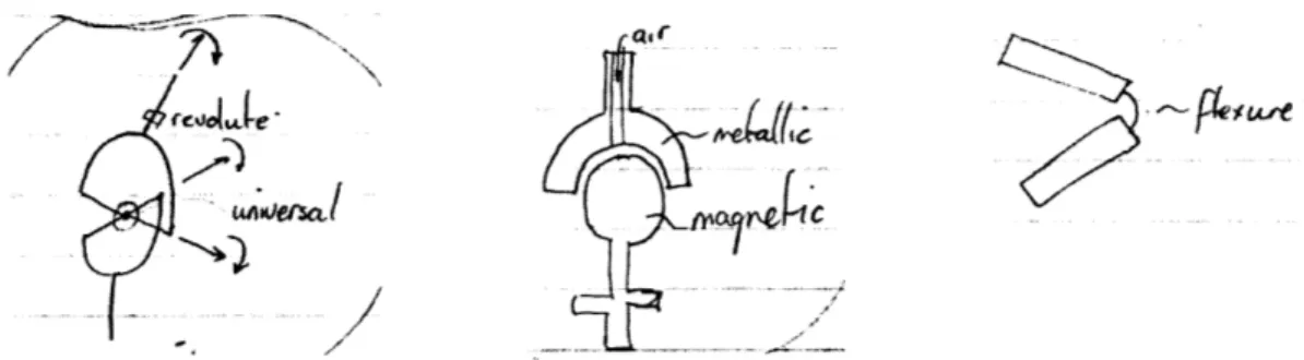
Figure 2.1 Modified universal joint Figure 2.2 Magnetic air bearing Figure 2.3 Flexure joint
The modified universal joint represents the simplest variation on the standard universal joint and implements an additional revolute bearing at one of the output shafts. This pro-vides for a high stiffness joint but does decrease the accuracy due to misalignment of the revolute bearing axis with the universal joint axis. To minimize this, the magnetic air bear-ing implements a ball and socket joint with all axes coincident at the center of the ball. It extends the flat pad bearing design by considering a hemispherical socket with a single orifice at the apex. Air is fed in through the shaft to provide the necessary air film and the ball is magnetized and the socket is ferromagnetic to provide the required preload. How-ever, separation is an issue, which is addressed by the flexure joint which takes an alter-nate approach by replacing revolute joints with flexible members, as is common in micro-electro-mechanical--system (MEMS) devices. While effective at the micrometer scale, these joints may not provide the range of motion and robustness required at the macro scale.
The slot and ball joint is a variant of the ball and socket design wherein the spherical ball is housed in a hemispherical socket. The preload is provided by a slotted retainer cup, which can rotate about the annular bearing. This design provides the requisite range of motion; however there exist singularities when the joint motion is perpendicular to the slot direction. Instead of implementing a rigid preload device, the spring preload design pro-vides the preload using several flexible springs attached from the socket edges to the ball apex. This provides a singularity free workspace, however stiffness varies at the extremi-ties of the workspace as the spring force becomes large, resulting in variable dynamic per-formance throughout the joint workspace.
N
&&AI),(I
Z
Figure 2.4 Slot and ball
F/0.7
-ewl~4
Figure 2.6 Double cup
Figure 2.5 Spring preload
// / £LI#/LAJL 6IA/#~C7toA/ ~
K
V -~ ~T~A~L~\
Figure 2.7 Sliding arm universal joint N
K..
~1
The double cup spring preload seeks to improve this performance degradation by imple-menting two sockets connected by shorter springs, with a spherical ball riding freely in
between. This design, however, does not provide the required amount of travel to achieve a workspace of 1800. The sliding arm universal joint provides more than the required travel by mounting two identical sliding mechanisms on either side of an annular bearing.
Figure 2.8 Modified universal joint Figure 2.9 Kinematic chain
The second modified universal joint uses a large annular bearing at the center of the joint, instead of a revolute bearing at one of the shafts, to achieve the third degree of freedom. The kinematic chain joint links three revolute joints mounted orthogonally to achieve three degrees of freedom; unfortunately this design is affected by multiple singularities in the workspace.
FL
Figure 2.10 Porous carbon air
~~i'1
Figure 2.11 Magnetic cup Figure 2.12 Sealed spring
The porous carbon air joint provides a variation to the single orifice ball and socket design by allowing the inlet pressurized air to enter through a porous carbon socket. This pro-vides a more homogeneous air transfer mechanism, however the robustness of the porous carbon compared to steel or aluminum must be established. The magnetic cup is a varia-tion of the magnetic ball design, wherein the socket is manufactured out of a non-ferro-magnetic material and then populated with magnets. The inlet air may be supplied through
a single orifice at the joint shaft or through multiple orifices arranged about the circumfer-ence of the socket. The sealed spring double socket design attempts to rectify the variable dynamic performance problems associated with the standard double cup design by allow-ing the sprallow-ings to freely rotate with the joint motion, while providallow-ing a preload force to prevent separation. Additionally, the spring enclosure can be combined with the seal to satisfy the sealing functional requirement.
TABLE 2.1 Joint strategy table
FUnctional Design Analysis References Risks Counter Measures
Categories Parmters
_
III
Spherical 3DOF 3 Intersecting axs Medical, Separation during Ieash notion Autorntive collision
2+1DOF 2 Intersecting ams Robotics Kinematic Improved nodels,
inaccuracy, backlash apply preload 1+1+1DOF 1 intersecting axis Serial robotics Singularities Configuration Contact Point Contact nrchanics Hertz Wear, friction Coating, rolling Type Rolling Dynanics Bearings Wear, friction Coating
Sliding Contact nrchanics Statics Wear, friction Inbrication Fluid Fluid dynanics Aerostatic Accuracy of film Manufacturing
bearings process
Preload Implicit Material nrchanics Statics Fatigue, wear Material strength
nrchanical
Fxernal force Forces and nonents Statics Separation Tether
The strategy sketches have been classified into various categories and key design parame-ters extracted; the results are shown in Table 2.1. The spherical motion function require-ment can be decomposed into the three kinematic chain alternatives; 1+1+I1DOF as commonly found in robotics applications; 2+1DOF as typified by the modified universal joint; and 3DOF as found in rod ends and other spherical mechanisms. The contact type can be divided into four key mechanisms; point, as found in static kinematic couplings for coordinate measurement machines; rolling, such as rod end or spherical bearings; sliding, such as the teflon coating used for the delta robot joints; and fluid such as aerostatic or hydrostatic bearings. Finally, the preload force can be applied by an external force such as a spring or a magnet, or by an implicit mechanism that is integral to the joint design, such as a mechanical retainer.
2.2.2
Concept Phase
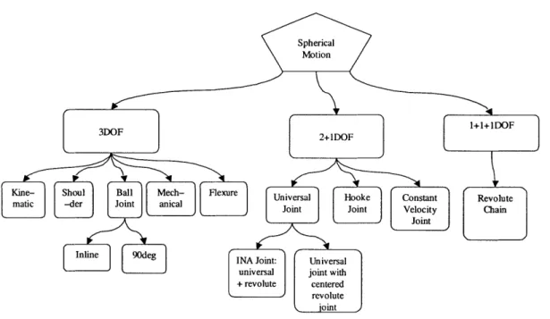
The strategy phase presented an array of idea sketches and distilled the key characteristics into a design parameter chart. The concept phase considers each design parameter of the strategy table and expands and evaluates suitable alternatives. The spherical motion con-cept table (Table 2.2) and concept tree (Figure 2.13) expand the three key motion mecha-nisms and evaluate each sub component in the same fashion as with the strategy phase.
TABLE 2.2 Spherical motion concepts
Functional Design Analysis References Risks Counter
Categories I Parameters I I Measures
3DOF Shoulder Sliding friction Powell Separation during Tether c ollsion
Kinematic Hertz contact Measurement Friction Coating, rolling elements
Flexure Beam bending Timoshenko Failure Lifetime prediction Spherical Sliding friction Pat pend: Complexity Simplify
mechanical 20010002964
2+1DOF Univ ers al+ Joint INA Kinematic Improved models
revolute kinematics inaccuracy
Hookes Joint INA Kinematic Improved models
kinematics inaccuracy
Slot and Bearing yield Patent: Singular position Design platform to revolute stress during 6,234,703 when axes aligned ensure that axes
use willneveralign
1+1+1DOF Revolute chain Robotics Denavit- Singularity Design
I _ I _ __ I lHartenberg constraints
The contact-type concept charts, detailed in Table 2.3, expand upon the four original con-tact mechanisms of point, rolling, sliding and fluid concon-tact. The point and rolling mecha-nisms are similar ideas comprising three small spheres mounted in the socket, supporting a larger ball kinematically as described by Hertz deformation theory (kinematic). The slid-ing surface ideas comprise a relative motion of flat surfaces as well as a slidslid-ing between a spherical ball and a hemispherical cavity (shoulder). The fluid film category presents air, oil and gas as alternatives, with air being the most viable due to the requirements of safety and sealing.
Spherical Motion
3DF 2+11D0F 111
FunciShoul Ball Mech- Flexure Universa Hooke Constant Revolute
matic -der Joint b anal Joint Joint Velocity Chain Joint
Inline adlonINA Joint: Universal universal joint with +revolute centered
--- revolute joint
Figure 2.13 Spherical motion concept tree TABLE 2.3 Contact type concepts
Functional Design Process Analysis References Risks Counter
Categories (Ideas) Measures
Point Ball on ball Hertz Hertz Wear, friction, Coating
contact deformation
Ball on groove Kinematic Slocum Wear, friction Coating
Coupling
Rollin g Ball on b all Hertz Hertz Deformation Coatin g contact
Ball on groove Kinematic Slocum W ear, friction Coating
Coupling
Slidin g Ball on Hertz Hertz Friction Lubric ation hemisphere contact
Flat on flat Statics Popov Friction Lubrication Fluid Air Fluid Flow Navier Use in dirty Seal
Stokes environments? Input and output of
air
Oil Hydro- Navier Use in clean Seal
dynamics Stokes environment?
Gas Fluid Flow Navier Safety? Seal
The preload concepts described in Table 2.4 expand the initial two strategy components of implicit mechanical and external force. The implicit mechanical coupling is an integral part of the joint design and is likely to be subject to deformation and yield considerations as described by structural mechanics analysis. The external force mechanisms may be sup-plied by springs, as with the delta robot; gravity which is commonly used for large coordi-nate measurement machines mounted on air bearings; vacuum as is typically used for small flat pad air bearings; or magnets where the magnetic field is used to provide an attractive force.
TABLE 2.4 Preload concepts
Functional Design Analysis References Risks Counter
Categories Parameters I Measures
Implicit Mechanical Material stresses Structural Failure Lifetime
Mechanical connection and strains mechanics prediction
External Magnet Magnet theory Magnetic Separation due to Tether force Permanent/ theory motion or collision.
electromagnet
Spring F=kx Linear elastic Change in stiffness Mount spring
mechanics dependent on along joint Z position, spring axis
constricts motion
Vacuum Fluid flow New Way Insufficient force Larger surface Tether Mechanical Statics Constricts motion Integrate into
constraint I I design
_Gravity F=mg Newton Insufficient force Combination
The three concept tables are combined to create a set of concept models, as described in Table 2.5. The spherical motion is restricted to three intersecting axes as the other two options (1+1+1DOF and 2+1DOF) result in kinematic inaccuracy. Each contact mecha-nism (point, rolling, sliding and fluid) is represented and both implicit and external forces are considered.
TABLE 2.5 Joint design concepts
Concept Diagram Description
Slot and A traditional shoulder joint design flavor,
Revolute using an angular contact bearing and a
separate cap to achieve greater working range and load capacity. Preload achieved
by constraining bearing races; inner race to bottom, outer race to cap.
Magnet pre- The ball is a standard tooling ball. The
loaded fric- hemi-spherical socket cavity is machined
tion contact by a spherical end mill. The magnets are
shoulder placed around the socket in pairs such that
joint the flux exits one magnet passes through
the ball, enters the other and makes the return path via a steel plate on the back of
the socket.
The friction joint is achieved by mounting the ball and socket in a fixture that defines the separation of the two components. A low-friction glue is injected into the
cav-Glue ity while the two elements remain in the
fixture and allowed to dry. The ball must be coated with a substance to ensure the
glue dries only to the socket.
Magnet pre- Using the same components as the
mag-loaded air netic preloaded friction joint, air is used to
bearing form the interface between the ball and
shoulder socket. Micro-nozzles are drilled through
joint the socket, or the socket is made from
porous carbon, in order to introduce air into the ball-socket interface. Possibility for self-cleaning. Must have precise ball and cap and large preload force to prevent
air separation. Ensure even spread of air and
magnets and analyze chance of instability and chatter.
Spring pre-loaded fric-tion/air contact shoulder joint i i Dual socket, single ball i i Magnet pre-loaded fric-tion kinematic socket and ball
The same socket and ball components are used, however the preload is achieved by means of a spring mounted between the socket and the ball structures, similar to [Hvittfeldt et al, 2002]. The spring
hous-ing on the ball side must be allowed to rotate in order to achieve the third degree
of freedom. The spring can be mounted directly to the socket or a similar housing
can be used for the socket side. Analyze the preload force and consider extreme cases where one side is limp and the other
tightened.
Two sockets are machined using a spheri-cal end mill. A ball bearing is used in the center to separate the sockets. The double socket design allows for modular con-struction. Preload can consist of springs or magnets; contact can consist of air or fric-tion. Must machine three precision sur-faces (2 sockets, 1 ball). Ensure that the socket, in extreme positions, does not catch the springs. Consider non-linearity
of springs at extreme positions. Three balls form the socket. They are each
mounted on magnets such that each mag-net is aligned in the same direction. This creates a flux path that is strongest at the apex of the three spheres - the magnets should be mounted on a steel plate to max-imize the magnetic field. The ball compo-nent is a larger ball bearing that is held in
place by the magnetic field. Analyze effect of dirt on the friction between the balls and the separation force from one of
the three balls. Investigate effect of rela-tive ball sizes and locations. Use machined surfaces with larger Hertzian contact area instead of balls to increase the
load-bearing surface and allow improved
I
_I
lubrication.From the set of six concept models, three are chosen: shoulder; kinematic; and slot and revolute. These are compared to the INA modified universal joint currently used for the ABB Tau robot prototype (Table 2.6). The shoulder joint utilizes magnets for preload and has the potential to implement either the surface or fluid contact mechanisms. The kine-matic joint also implements magnetic preload and could illustrate the point or rolling con-tact mechanisms.
TABLE 2.6 Concept evaluation chart
Functional Specification Baseline
Requirement
INA
Safety No separation 0
Accuracy Very high (low pm) 0
Workspace >135deg 0
Stiffness High (>10N/pm) 0
Robustness Robust 0
Lubrication low/no lubrication 0
Weight Lightweight 0
Temperature Low effects 0
Maintenance Low/no maintenance 0
Modular Low part count 0
Scaleable reason 0
Singularities None 0 Restrictions None 0
Load capacity Application defined 0
Preload No separation 0
motion Open 0
Modeling existing 0
Energy usage Minimize energy 0 Elegance Consistent aesthetic 0
Materials Minimize cost 0
Sealing Full seal 0 Calibration existing 0 0 Strategy 3 Slot+revolute + 0 0 0 0 0 0 0 0 0 0 0 0 0 0 + 1+
2.2.3 Module Phase
The chosen concept models are further developed into three prototypes. The shoulder con-cept is implemented with the sliding surface contact mechanisms (Table 2.7); the kine-matic concept is used to illustrate point and rolling contact mechanisms (Table 2.8). All three implementations use magnetic preload and the three intersecting axes spherical motion design.
TABLE 2.7 Sliding and fluid contact joint generations
Generation Description
Original prototype comprising a tooling-ball like ball component mating with a hemispherical socket. The socket in turn has a hemispherical cup machined into the
flat surface to accommodate the ball. The contact type could be air (either through porous socket materials or through micro-nozzles) or direct contact via a low fric-tion material that could be injected into the gap (fixturing
required). This design allows less than 1800 of motion due to the hemispherical socket and large shaft size.
The socket is simply a turned cylinder forming a cone at the socket end. This eliminates the need for connection of the socket to the shaft; the shaft end can also be threaded in the same turning process. The mating surface is
The design incorporates a larger ball to socket ratio and smaller shafts. This allows for more than 1800 of motion in the Rx (roll) and Ry (pitch) directions. It remains to be determined how much material is required for the socket, with consideration for stiffness, strength, robustness and
effect of preload.
Simplified socket (probably chamfer off edges to provide more range of motion). Allows 1800 in all directions with
a 700 cup size and the preload magnet slots at 35*. These
slots are drilled through 6mm holes that can accommo-date permanent or electromagnets. Magnets are arranged
in pairs to allow for increased magnetic force (two pole design) while maintaining a small footprint on the surface
of the socket. The ball is a 50mm chrome steel ball
-both ball and socket have a 12mm shaft glued, EDM or screwed into a periphery.
Simplified socket machined from diameter 60mm steel or aluminum cylindrical stock. 8 holes are drilled about the
circumference of the socket at 45* to mount the magnets
and provide the preload
TABLE 2.8 Point and rolling contact joint generations
Generation Description
First concept model. Three tooling balls form the socket and each contact at a point with a larger tooling ball which connects to the second shaft. The magnets are connected to the base of each of
the socket tooling balls.
Basic proof of concept prototype. Ball bearings and loose magnets are arranged in the kinematic configuration and the preload force tested for
var-ious magnet orientations. Maximum force is achieved by aligning all magnets with the same
polarity.
Basic solid model. The rolling contact prototype is shown with the ball transfers (solid ball bearing
mounted on smaller ball bearings to allow free rotation of the ball within the enclosure) mounted
about the socket. The smaller holes on the same annulus as the ball transfers are for the 6mm mag-nets. Additional holes are required about a second
ring around the socket to provide a comparable preload force to the ball and socket prototypes.
2.2.4 Manufacture
Three prototypes have been implemented, each comprising an aluminum socket machined from 3.5" (90mm) stock and a 2" (50mm) diameter solid steel ball bearing. Separation between ball and socket is prevented by a magnetic preload force supplied by a ring of magnets about the circumference of the socket. Three primary contact mechanisms have been investigated: point, rolling and surface contact. The fourth mechanism, fluid contact, is presented in Chapter 4. The point contact prototype locates the ball kinematically upon three spheres embedded within the socket. Given minimal Hertz deformation due to the relatively low preload forces, the primary source of error for this type of joint is the accu-racy of the ball. The main problem with this design is the friction inherent in the point con-tact region. The rolling concon-tact prototype seeks to alleviate this friction problem by utilizing commercially available rolling ball-transfers mounted in the socket in place of the solid steel spheres. This dramatically reduces the friction but potentially increases the errors due to the additional influence of the ball transfer accuracy. The sliding contact pro-totype creates an accurate mounting surface through replication with a Teflon-laced epoxy. This provides a larger contact region to minimize contact stresses with reduced friction due to the Teflon contact surface. Despite the potential accuracy of such a joint, the friction is still significant. The assembly models and manufactured prototypes are detailed in Figure 2.14 through Figure 2.23.
Figure 2.15 Sliding contact exploded model
Figure 2.16 Rolling contact assembly model Figure 2.17 Rolling contact exploded model
Figure 2.21 Point contact Figure 2.22 Rolling contact Figure 2.23 Rolling contact joint
Machining process
1. Cut 3.5" (90mm) stock to correct length
2. Fix in 3-jaw chuck
3. Turn face
4. Rough and fine turn outer surface
5. Drill center 1/16" (1.5mm) hole
6. Drill shaft 1/12" (2mm) hole
7. Remove from lathe and fasten on boss end
8. Face, rough and fine turn inner hole
9. Mount the face in an indexing chuck and set to desired angle (450 for shoul-der, 21'/52* for kinematic). Mount in mill.
11. Drill desired hole ( ", 12mm for shoulder, ", 6mm for kinematic). Index to next angle and repeat.
Replication process
1. Glue the desired number of magnets into a cylinder.
2. Attach one disk of thickness 1/32" (0.75mm) to the end of each magnet cyl-inder.
3. Place several 1/16" (1.5mm) O-rings between the ball and socket. Mount the assembly in a mill. Determine the Z-axis of the assembly by tramming. Note the position of the assembly in the mill. Coat the ball with a release fluid
(e.g. oil).
4. Insert the magnet cylinder and butt up against the ball with the plastic disk end. Glue the magnet cylinder in place with Loctite. The 1/32" (0.75mm) plastic spacer disk will ensure that the magnet cylinder sits 1/32" (0.75mm)
above the surface of the socket.
5. Remove the ball, remove the 1/16" (1.5mm) O-rings and 1/32" (0.75mm) plastic spacers.
6. Replace the ball such that the position of the mill is at the same position as noted. The ball will therefore be 1/16" (1.5mm) from the socket in all places except for where the magnets are 1/32" (0.75mm) from the ball.
7. Inject the replication fluid through the small hole in the socket center into the 1/16" (1.5mm) cavity. Continue until the fluid fills the entire gap. Ensure no air pockets by injecting fluid slowly from the bottom of the socket and allowing fluid to overflow socket edge. Bubbles in the fluid will exit before the epoxy is able to set fully.