Design and Implementation of Liquid Cooling System for ArchiMITes Vehicle by
Sam Hui
B.S., Mechanical Engineering (2011) Massachusetts Institute of Technology
Submitted to the Department of Mechanical Engineering in Partial Fulfillment of the Requirements for the Degree of
Bachelor of Science in Mechanical Engineering at the
Massachusetts Institute of Technology June 2011
ARCHIVES
MASSACHUSEETTS INSTITUTE OF TECHNCLOG'YOCT20 2011
LIBRARIES
02011 Massachusetts Institute of Technology All rights reserved
Signature of Author _ __
Department of Mechanical Engineering May 6, 2011
Certified by
Evelyn N. Wang
.)
Esther and Harold E. Edgerton Assistant Professor of Mechanical Engineering Thesis Supervisor
Accepted by
John H. Lienhard V
Collins Professor of Mechanical Engineen Chairman, Undergraduate Thesis Committee
DESIGN AND IMPLEMENTATION OF LIQUID COOLING SYSTEM FOR ARCHIMITES VEHICLE
by SAM HUI
Submitted to the Department of Mechanical Engineering on May 6, 2011 in Partial Fulfillment of the requirements for the Degree of Bachelor of Science in
Mechanical Engineering ABSTRACT
MIT Vehicle Design Summit is building ArchiMITes, a lightweight hybrid vehicle with a modular auxiliary power unit. For testing purposes, the vehicle platform will first be built as an all-electric vehicle. It will be powered by five lithium ion batteries that generate a total of 700 W of heat. Without a cooling system, the batteries will quickly rise above 50 'C and become damaged. This project seeks to design and put together a liquid cooling system to remove the heat from the batteries. Calculations indicate that the battery cell temperature will be 17.39 'C above the ambient temperature. This temperature difference incorporates a factor of safety of 2. Further studies on battery placement, working fluid fill methods, and fan and pump control are recommended.
Thesis Supervisor: Evelyn N. Wang
Title: Esther and Harold E. Edgerton Assistant Professor of Mechanical Engineering
Thesis Supervisor: Anna S. Jaffe
Acknowledgements
I would like to thank Professor Evelyn Wang and Anna Jaffe for their support and guidance in this project.
Table of Contents
1 Introduction - The ArchiMITes Project 6
2 The Battery 6
3 Cooling Methods 7
3.1 Selection of Cooling Method... 7
3.2 Basic Components of Liquid Cooling System ... 7
4 Modeling the Heat Transfer 8 4.1 H eat Flow Path... 9
4.2 Heat Generated by the Batteries... 10
5 Selection of Parts 10 5.1 Selecting the Radiator... 11
5.2 Selecting the Fan... 12
5.3 Selecting the Pum p ... 13
5.4 Selecting the C old Plate... 15
5.5 Selecting the Thermal Interface Pad...17
5.6 Selecting the Expansion Chamber... 18
5.7 Hose, Fittings, Teflon Tape, and Clamps... 18
6 Pressure Drop 20 7 Finding the Hottest Cell Temperature 21 7.1 Temperature of Fluid Entering Radiator... 21
7.2 Temperature Rise of Fluid... 22
7.3 Temperature Gradient Across Cold Plate... 22
7.4 Temperature Gradient Across Thermal Gap Pad... 23
7.5 Tem perature of the Cell... 23
8 Assembly 24
9 Discussion 25
List of Figures
Figure 1 The prismatic battery module ... 6
Figure 2 Schematic of fluid flow path ... 8
Figure 3 Therm al circuit m odel ... 9
Figure 4 Specifications for M14-120 heat exchanger ... 11
Figure 5 Radiator-fan assembly ... 13
Figure 6 Pump specification ... 14
Figure 7 Pum p ... 15
Figure 8 Cold plate specifications ... 16
Figure 9 Thermal gap filler specifications ... 17
Figure 10 Expansion chamber ... 18
Figure 11 Hose-fitting-cold plate assembly ... 19
Figure 12 Temperature of the system at various locations ... 24
Figure 13 The liquid cooling system ... 25
List of Tables
Table 1 Operating properties of the batteries ... 10Table 2 Fan specifications ... 12
Table 3 Pump performance ... 14
Table 4 50 % water - 50 % ethylene glycol fluid properties ... 16
T able 5 Therm al gap pad ... 17
Table 6 Hose specifications ... 18
Table 7 Flow properties of heat transfer fluid ... 20
1
Introduction
-The ArchiMITes Project
Started in 2009, ArchiMITes is the first Vehicle Design Summit vehicle to be built by a team composed mainly of MIT students and alumni. The vehicle will be a series hybrid; it will have a primary electric power source backed up by a modular auxiliary power unit (APU). Since the APU is modular, several different designs based on different fuel types can be tested in the vehicle. In additional to the modularity of its internal components, the vehicle will be lightweight and aerodynamic - the carbon fiber body is custom designed to have a low coefficient of drag, while most of the suspension is fabricated from lightweight aluminum.
Before ArchiMITes is constructed as a hybrid, it will first be built and tested as an all-electric vehicle. The vehicle will be powered by five large lithium ion batteries. As the batteries will generate heat, a liquid cooling system will need to be designed and implemented. This is the motivation behind this thesis.
2
The Battery
The ArchiMITes vehicle will be powered by five Lithium ion battery modules, generously provided by A123 Systems. Each module, roughly in the shape of a rectangular prism, contains sixty-six AMP20 prismatic pouch cells wired in series and in parallel. Sets of twenty-two cells are wired in parallel, allowing the prismatic battery modules to supply a total of 21 kWh at 360 Volts. The dimensions of each module are 578 mm (22.75") by 164 mm (6.46") by 243 mm (9.57").
3
Cooling Methods
While the batteries are in use, the current running through the packs will generate heat through Joule heating. This heat will need to be dissipated to prevent the modules from reaching too high of a temperature. The battery temperature should be kept under 50 'C.
There are two common methods to transfer the heat away from the modules. The first of these methods is air cooling. In this method, a fan blows air over the battery modules, drawing the heat away from the modules and into the air. The second method is liquid cooling. Heat from the batteries is transferred into a fluid, which flows to a radiator. From there, the heat is transferred to the air.
3.1
Selection of Cooling Method
Each of the cooling methods listed in the previous section has its own advantages and disadvantages. The air cooling method requires fewer components, but requires a more powerful fan and rejects less heat than the liquid cooling method. In contrast, the liquid cooling method requires several more components and runs the risk of leaks, but rejects more heat than the air cooling method.
After comparing the two systems, a liquid cooling system is chosen for its higher cooling power.
3.2
Basic Components of Liquid Cooling System
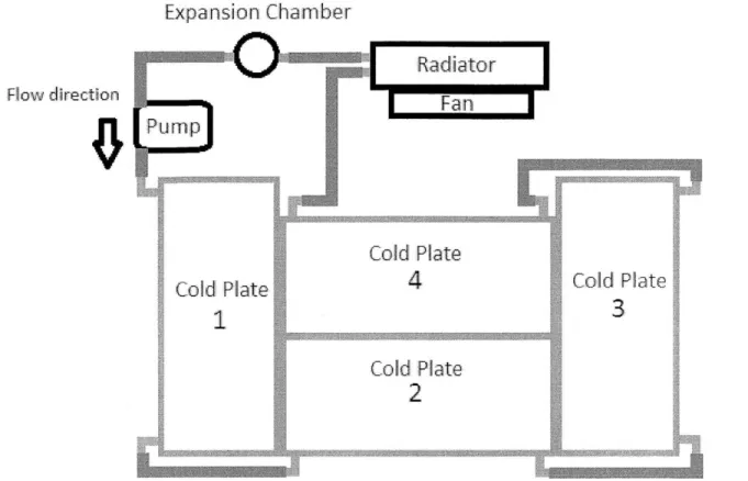
The major components of a liquid cooling system include the interface between the heat source and the working fluid (in this design, a cold plate), the working fluid itself, the pump, and the radiator. These components are laid out in the flow path schematic in Figure 2.
There are also a number of other components that should be included, such as a thermal pad interface to aid in heat transfer between the cold plate and the battery, an expansion chamber to account for thermal expansion of the working fluid, and a fan to aid in heat removal at the radiator.
Other considerations include the power supply for the pump and fan, and the fittings and tubing for the fluid flow.
Expansion Chamber
Flow directionCold Plate
d Plate4
Cl Plte Cold Plate ~9 Cold PPate2
... ......... ......Figure 2. Schematic of flow path of the working fluid. After leaving the pump, the fluid traverses the four cold plates, absorbing heat. It then enters the radiator where it transfers the heat
to the air before passing the expansion chamber and re-entering the pump. The battery modules will be placed side by side. There will be one battery module each on plates I and 3 and three
modules on plates 2 and 4
4 Modeling the Heat Transfer
In the thermal model, it is assumed the system is at steady state. Furthermore, to simplify calculations, it is assumed the heat transfer is one dimensional. This assumption is valid because the temperature difference from the battery cells to the cold plate is relatively larger than the temperature difference across the individual cells. At steady state, the majority of the heat will flow from the battery cells to the cold plate, instead of from one cell to another. To be conservative, it is also assumed that there is no heat transfer from the battery to the surrounding air.
4.1
Heat Flow Path
Heat is generated in the batteries through Joule heating. In this system, the heat flows from the battery cell to the battery module surface. From there, the heat flows through the thermal gap pad and into the cold plates. The cold plates then transfer the heat to the working fluid.
The heat transfer will be modeled by analogy to an electrical circuit. This comparison is shown in Figure 3. Each component in the liquid cooling system has a thermal resistance impeding the flow of heat from a higher temperature source to a lower temperature source. In an electrical circuit, the voltage drop across a resistor is equal to the current multiplied by the resistance. In a thermal circuit, the temperature drop across two points is equal to the heat flow multiplied by the thermal resistance between the points. By using a circuit model, given a heat flux and the thermal resistance, the temperature of each part in the cooling system relative to the other parts can be determined.
Thermal Circuit
Temperature in Battery Cell Resistance Between Cell low Termperature of Battery Su
Resistance Within Therm
Temperature of Cold Plate S Resistance Within Cold P Termperature of Cold Plate
and Battery Surface
rface Curren al Gap Pad u rface late Tubing Surface Electrical Circuit Voltage 1 Resista t Flow Voltage 2 Resista Voltage 3 Resista Voltage 4
Figure 3. Diagram comparing the thermal circuit model to an electrical circuit. It is assumed that there is no thermal resistance between any two surfaces in contact. The upper surface of the gap pad and the battery surface are assumed to be the same temperature. Likewise, the lower surface of the gap pad and the upper surface of the cold plate are assumed to be the same temperature.
The battery module is packed with cells, which allows the assumption of one dimensional heat transfer in the calculations. The battery cells are all approximately the same temperature when compared to the temperature of the battery surface, so all the heat flows toward the surface.
Heat F
nce 1
nce 2
4.2
Heat Generated by the Batteries
The first step in designing a liquid cooled heat exchanger is to determine the total heat to be rejected. As all the heat will be generated though Joule heating, we can use the equation
Q=2 R
to estimate the heat produced, where I is the current running though the battery modules and R is the electrical resistance.
Previous work on the electrical component has yielded a RMS current of 21 A. Although the derivation of this value is beyond the scope of this paper, this is the value that will be used in the calculations.
It is assumed that the RMS current of 21 A runs through each cell. Since three sets of 22 cells are wired in series, a current of 63 A runs through the entire module. Given that the electrical resistance of the battery module is 18 mOhm, the heat generated is calculated to be 71 Watts. To be conservative, a safety factor of 2 is introduced. Table 1 shows the heat generated by a single cell, a sixty-six cell module, and a pack of five modules.
Cell Module (66 cells) Pack (5 modules)
Resistance 2.4 mOhm 18 mOhm 90 mOhm
Current 21 A 63 A 63 A
Heat Generated (Q) 1.058 W 1.058 W*66= 70 W 70 W* 5 = 350 W
Q
(safety factor of 2) 2.116 W 140 W 700 WTable 1. Operating properties of the batteries.
The liquid cooling system is designed with the assumption that each of the five modules will generate at most 140 W of heat, and the total heat output will be at most 700 W.
5
Selection of Parts
The next step is to select the parts for the cooling system. Each part is selected with the overall system in mind. When possible, the connections, fittings, and power supply are all standardized.
5.1
Selecting the Radiator
The function of the radiator is to efficiently dissipate heat. Typical radiators include multiple tubing passes to extract more heat from the fluid as well as fins to increase the surface area for convective heat transfer. The ideal radiator for this project would be compact and yet able to dissipate enough heat. Lytron's M14-120 heat exchanger fits the criteria. The heat exchanger is roughly square, with dimensions 356 mm (14.0") by 325 mm (12.25"). Although this may seem large, it only uses one fan instead of two, which makes it half as large as the M14-240 model (356 mm by 630 mm). The copper tubing has an outer diameter of .5".
Figure 4 shows a picture of the heat exchanger, along with its dimensions. Also included is a graph depicting the expected values of Q/ITD for different fluid and air flow rates;
Q
is the heat to be rejected and ITD is the initial temperature difference of the ambient air and the fluid entering the radiator.M14-120
/2 ~pmj
Figure 4. Specifications for M14-120 heat exchanger. The heat exchanger contains copper tubing joined to aluminum fins.
M14-120
M14-120
ji!
1Ell
The graph in Figure 4 shows that for fluid flows in the range of 1 to 4 gallons per minute at an average airflow of 400 cubic feet per minute, the value of Q/Initial Temperature Difference typically ranges from 100 to 150. Previous calculations show that the total heat output of the five packs is 700 W. From this information, the initial temperature difference is estimated to range from 4.6 C to 7 C.
5.2
Selecting the Fan
The M14-120 heat exchanger also includes a 10" diameter Ostro fan. However, the fan requires a 110 Volt power supply, making it unsuitable for use in a vehicle. An appropriate replacement fan would have roughly the same diameter and run on a small lead acid battery.
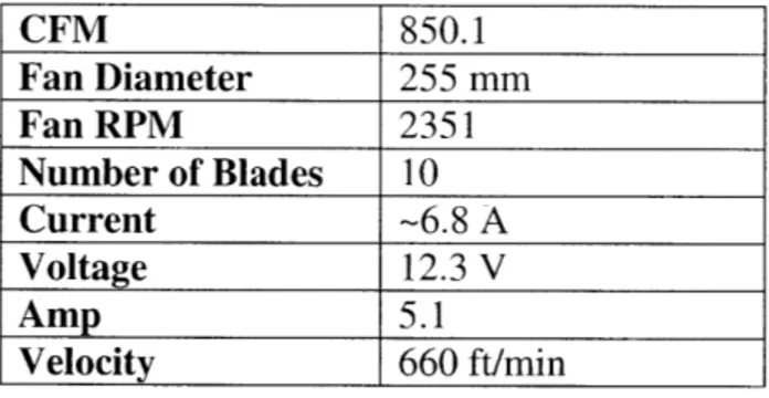
The 10" Mishimoto Slim Electric Fan, in Figure 5, is selected for this application. Not only does this fan run on a 12 V power source, it is also thinner and can force an air flow rate of 850.1 cubic feet per minute. A summary of its specifications is shown in Table 2 below. A challenge with this fan is that it needs to be custom attached to the radiator.
CFM 850.1 Fan Diameter 255 mm Fan RPM 2351 Number of Blades 10 Current -6.8 A Voltage 12.3 V Amp 5.1 Velocity 660 ft/min
Table 2. Fan specifications.
The Mishimoto fan has 4 tabs with bolt holes for securing the fan to the radiator. By superimposing the fan on top of the radiator, there is just enough space to drill four holes in the aluminum cover of the radiator for the bolts. After securing the fan to the radiator with four M8 bolts, the radiator-fan assembly is completed.
Figure 5. The fan is mounted onto the radiator with four bolts.
5.3
Selecting the Pump
With the fan and radiator assembly completed, the pump can now be selected. There are numerous types of pumps available on the market, each with its own limits and functionality. Some considerations taken into account while selecting the pump were the voltage required to run it, the flow rate, the fluid and pressure compatibility, and the inlet and outlet ports.
After looking over several different pumps, SHURflo's Refrigeration Circulation Pump (model # 2095-273-200) was chosen for the cooling system. Figure 6 shows that this pump runs on 12 V - the same as the Mishimoto fan, which allows both to run off the same power supply. The pump also has the same port connections as the radiator.
APPL!CAT!ON
12\/ DC Refrgeration cold plate tirculatioin
This pump mav e used for genrac resh wat transf
PUMP: Type: Ports: Liould: Dry-Prime inlet Pl: Run Wry: 3 Charnber Diaphragm 112-14 NPSM-M ale. 130 F 54 ' Max 6 feet [1 82 Mj :3 PSI [2.1 Ja Max Yes ELECTRICAL:
Mo t o 12VDC Permanent Magnet, Continuous Duty
Figure 6. Pump specifications. The pump comes with " barbed to %" NPSM male fittings.
Table 3 shows the pump performance at various pressures. Although the pump is a positive displacement model, the flow rate actually varies depending on the pressure.
TYPICAL PERFORMANCE
__PRESSURE__ BR ______ PL FLOW VPLM-MP
:
:CURRENT0.0 __1.-75 0 66 1.28
1.4 0 1.15 4.4 2 65
1 2.8 40A 0. 651 22I* 9
4.1 60 025 09 2 80
5.5
80
0.00
00
1
345
Table 3. Pump performance at various pressures. The maximum flow rate is 1.75 GPM. Pressures above 80 psi may damage the pump.
Figure 7 shows the pump. It is a three diaphragm positive displacement model. There are four mounting holes located on the bottom.
Figure 7. The pump. Also shown are the barbed fittings connected to the inlet and outlet ports.
5.4
Selecting the Cold Plate
The role of the cold plate is to provide a liquid to solid interface for the heat transfer. For this project, Solid State Cooling has generously provided four cold plates. Each of the aluminum cold plates is roughly 22.0" by 9.725" by .9". This cold plate design allows the fluid to make multiple passes along the length of the plate, with the inlet and outlet on the same side. Figure 8 shows the pressure drop and thermal resistance for various fluid types and flow Tates.
6 7 8 Rate (gpi)
Pressure Drop
71
J...
k...t
..
..
20) C,
Fluid Flow Rate (gpm)
-50.50 ETG/water
-Water
Figure 8. Since the temperature of the system will be most likely be above 20 'C, only two of the four lines in the left graph need to be considered.
For the working fluid, a mixture of 50% water with 50% ethylene glycol is chosen. Water has a higher heat capacity allowing it to store more heat per unit mass. Ethylene glycol lowers the freezing temperature, which prevents tubing from bursting during the winter months. The properties of this fluid mixture are summarized in the table below.
50/50 ETG/Water Fluid Properties SI units
Specific heat capacity at 26.7 'C (increases with .824 Btu/lb. F 3450 J/kg K temperature)
Specific gravity /density at 48.9 'C 1.070 1064 kg/ m3
Dynamic viscosity at 37.8 'C 2.15 centipoise 2.15*10-3 Pa-s
Table 4. Properties of the 50% water with 50% ethylene glycol mixture
16 0.0015 __ 0.0014 0.0013 0.0008 _ 0. 0007 0.0006 1 2 3 4 5 6 7 E 2 3 4
5.5 Selecting the Thermal Interface Pad
A thermal pad is placed between the battery and the cold plate to improve heat transfer. For this purpose, the thermal gap-filler AOS Non-Silicone 52041 Heat Sink Compound made by AOS Thermal Compounds is used. Not only does the pad fill in the tiny gaps on the battery surface, it also provides some vibration damping for the battery. This thermal pad will be 1/8" thick and will be sized to fit the battery surface, 22.75" x 6.45". Figure 9 shows the thermal gap pad specifications. The thermal pad has a thermal conductivity of 2.2 W/m K at 36 'C. This information, along with the calculations for the thermal resistance, is summarized in Table 5.
Property
Consistencv (Un wrIked Specific Grav ity. 2*C
Bleed. 41@ 200*C, 24 Hi _ /t
Ev aporation. 2-,_00*C. 24 His. %jWi
Thernal (onductivity, WV/m. K Electrical Properties
DielctilcSreth .5ga.Vm
Dielectri IStrengt oherW exp'osure to 85'C/85 R.e' H tir 48 i ur.
Dielectric Coinmt, 25"C @ 1,00 Hz
DissipaItion Factor. 253C (71,000 Hz
Volume Res.isuvv H hm-em Operating Teiperature Range
Appearance Q_ I 10 2.72 ~is 5.0 0.0027 -40*C to 200*C(
(.rav lid between PET
sheets Test NIethod ASM D1)7 AST D -STM-341MODIFED11 FTM-2 MIODIFIED1 A\1,. STM D 547I-06 (0 3(," . 5. and 20 i1 \STNI D-149 ASTM1 [! 15 AST D-150 2W
Figure 9. Thermal gap filler information
Thermal Pad SI units
Length, 1 22.75" .578 m
Width, w 6.45" .164 m
Thickness, t 1/8" .0032
Thermal Conductivity, k 2.2 W/ m K
Area, A 146.7 square inches .095 square meters
Thermal Resistance = t/(k * A) .015 0C/W
Table 5. A thinner thermal gap pad would decrease the thermal resistance, but would provide less damping.
5.6
Selecting the Expansion Chamber
The expansion chamber allows the liquid to expand or compress without significantly changing the fluid pressure in the system. The chamber contains a reservoir of air, which compresses more readily than the working fluid. For this liquid cooling system, product 2269K23 from McMaster, pictured below, is selected. It can hold 25 cubic inches of liquid.
Figure 10. The expansion chamber is only rated to 15 psi. The inlet is 34" NPT male.
5.7
Hose, Fittings, Teflon Tape, and Clamps
The last components required for this cooling system are the hose and the parts attached to it. The hose needs to be compatible with the heat transfer fluid, and strong enough to withstand the fluid pressure. Additionally, since the connections on the pump and radiator are " barbed fittings, a hose with a " inner diameter is desired. With these considerations in mind, a clear, braid reinforced polyethylene tubing is chosen for the system. Its properties are listed in the table below.
Imperial Units SI Units
Outer Diameter .74" 1.88 cm
Inner Diameter .5" 1.27 cm
Wall Thickness .12" 0.30 cm
Maximum Pressure 150 psi 1034 kPa
Bend Radius 5" 12.7 cm
Table 6. The maximum pressure is greater than the pump's maximum output pressure. Brass fittings are used to connect the hose to the cold plates. The cold plates provide 3/8" female NPT connections. Since the tubing has an inner diameter of .5", the brass fittings chosen have a .5" barbed connection on one end and a 3/8" male NPT connection on the other.
While fluid is flowing through the hose, the pressure will cause the tubing to radially expand. To prevent the hose from slipping off the brass fittings, a hose clamp is used. For this project, there are two types of hose clamps used on the fittings - worm gear clamps and ear clamps. Worm gear clamps require a screwdriver to change the radius of the clamp. They are reusable, but slow to install and not great for tight spaces. Ear clamps, on the other hand, require a special tool to crimp a specific part of the clamp, decreasing the radius. They are relatively quicker to install and have a low profile, but are not reusable. Ear clamps are used in two locations with a low clearance, while worm drive clamps are used elsewhere.
Figure 11. An ear clamp secures the hose to the brass fitting, while the white Teflon tape seals the gap between the threads.
6
Pressure Drop
Calculating the pressure drop is an iterative process. Since the fluid flow rate is a function of pressure, an estimated flow rate is first used in the calculations. Adjustments to the estimate are made until the pressure drop corresponding to the estimated flow rate and the calculated pressure drop are roughly equal.
From the specifications, the pressure drop from the fluid traversing the radiator is 15 psi. Since the flow rate from the pump is at most 1.75 GPM, Figure 8 shows that the pressure drop in each cold plate is less than 1 psi.
To calculate the pressure losses from the tubing and fittings, the equation
L pv2 AP = f * - * --D 2
is used -relating the pressure drop to the friction factor times the equivalent pipe length, density of fluid and velocity.
Since the combined pressure losses from the radiator and cold plates is 19 psi, an estimated pressure drop of 20 psi is used for estimating the flow rate. From Table 3, the flow rate corresponding to a pressure of 20 psi is 1.15 GPM. With the information about the fluid properties (see Table 4) and the flow rate, the flow properties can now be calculated.
Heat Transfer Fluid = 50/50 ETG/Water SI Units
Flow rate 1.15 GPM .073 liters /s
Pressure drop < 1 psi
Pipe diameter .5 in 1.27 cm
Flow velocity .58 m/s
Mass flow rate .078 kg/s
Reynolds number 3645 = turbulent flow
Table 7. Flow properties of the heat transfer fluid.
The Reynolds number is used in friction factor calculations. The Handbook of Polyethylene Pipe gives the absolute roughness of polyethylene tubing as .00012". Dividing this value by the diameter yields a relative roughness of .00024. From a Moody chart, we see that the Friction factor for this relative roughness and Reynolds number is .045.
We can sum up the major and minor losses into one equation. There are at most 25 feet of straight piping, and 9 elbow joints (8 attached to the cold plate, and 1 attached to the pump). L/D for 25 feet of piping is 25'/.5"=600. Each elbow joint has an equivalent L/D of 40. Thus, the pressure drop is calculated as:
1064 (k 49 MS)2
AP = .045 * (600 + 9 * 40) * M16 = 517 Pa = .80 psi
There is only a .80 psi pressure drop for the fluid running though the tubing. Along with the 15 psi pressure drop from the radiator and the 4 psi pressure drop from the cold plates, the total pressure drop is then 19.8 psi, which is close to the initial estimated value of 20 psi.
7
Finding the Hottest Cell Temperature
There is now enough information to calculate the temperature of the battery cells. Using the data from the radiator, the temperature difference of the fluid entering the radiator and the ambient air can be found. With this information, the temperature at the cold plate can be found. Finally, using the thermal circuit model, the temperature at the thermal gap pad, battery surface, and battery cell can be calculated.
7.1
Temperature of Fluid Entering Radiator
Now that the fluid flow rate into the radiator and the air flow rate across the fins are known, the Q/ITD can be calculated. Pressure drop calculations yield a fluid flow rate of 1.15 GPM and the specifications of the fan yield an air flow rate of 850 CFM. Using the graph in Figure 4 and extrapolating, the value of Q/ITD is around 145 W/0C. Since the total heat output is
700 W, the initial temperature difference between the fluid and ambient air is 4.83 'C.
7.2
Temperature Rise of Fluid
At steady state, all heat produced by the battery is transferred to working fluid. Given the mass flow rate and the heat capacity of the fluid, the equation
Q
=rnCAT
can be used to find the temperature rise of the fluid after it travels through the four cold plates. The values of 700 W for the heat generated, .078 kg/s for the mass flow rate, and 3450 J/kg K for the heat capacity are substituted into the equation:
700 W = .078 - * 3450 - AT
s kg K
AT = 2.60 C
At steady state, the fluid leaving the cold plates is 2.60 'C hotter than the fluid entering it. Since the temperature of the fluid entering the radiator is 4.83 'C above ambient, the temperature of the fluid leaving the radiator and entering the cold plate is 2.23 'C above ambient.
7.3
Temperature Gradient Across Cold Plate
For this calculation, the thermal circuit model can be applied. Assuming a one dimensional heat flow, the temperature difference across the cold plate is equal to the heat flux multiplied by the thermal resistance. Figure 8 shows the thermal resistance of the cold plate for various flow rates. Since the water/ethylene glycol mixture will be moving at 1.15 GPM, the corresponding thermal resistance is .0015 'C/W. This value is for the entire surface of the cold plate, with an area of 214 square inches. However, one battery module will only cover 148 square inches. The thermal resistance for one module is therefore
214 in2 C C
-*.0015 - =
.0021-148 in2 W W
The heat flux corresponding to one battery module is 140 W. Multiplying this value with the thermal resistance yields 0.30 0C.
7.4
Temperature Gradient Across Thermal Gap Pad
Assuming a one dimensional heat flow, the temperature difference across the gap pad is equal to the heat flux multiplied by the thermal resistance. For one battery module, the calculations in Table 5 show that the thermal resistance is .015 'C/W. Multiplying this value with 140 W yields a temperature difference of 2.1 0C. Since the battery surface is pressed against the top surface of the gap pad, the temperature of the two surfaces are the same.
7.5
Temperature of the Cell
The final step is to determine the temperature difference between the cell and the surface of the battery. This can be found using the following equation:
Tmax = Qceu X R + Tbatt external
The above equation states that the temperature difference between the cell and the battery side surface is equivalent to
Qe1,
the heat output of the cell multiplied by R, the thermal resistance from the cell to the side surface. The A123 battery modules have a thermal resistance of 4.8 'C/W from the center of the cell to the bottom surface of the battery. Using our value of 2.116 W for the heat output per cell, and the equation above, the maximum temperature in the cell is calculated to be 10.16 'C larger than the temperature at the bottom surface.The hottest location on the cold plate is right where the fluid starts to return to the radiator. At this location, the fluid temperature is 4.83 'C above the ambient air temperature. The temperature difference between the fluid and the surface of the cold plate is 0.30 'C. From there, the temperature gradient across the gap pad is 2.1 'C. Finally, the temperature difference between the surface of the battery module and the cell is 10.16 'C. Summing these calculated values indicates that the temperature of the cell is 17.39 'C above ambient. Figure 12 expresses these calculations in a graph.
20 18 + 16 14 E 12 0 ' 10 1 2 34 0A
Location along thermal circuit
Figure 12. The numbers on the independent axis are explained in Table 8
Location Calculated temperature above ambient
0 Ambient air 0 OC
I Hottest fluid temperature 4.83 OC 2 Cold plate-gap pad interface 5.13 OC 3 Gap pad-battery surface interface 7.23 OC
4 Battery cell 17.39 OC
Table 8. Locations and temperatures corresponding to various numbers in Figure 12.
8
Assembly
With all the parts selected, the cooling system can now be put together. Figure 13 shows the system as a separate module outside the vehicle. All hose-fitting connections are secured with either a worm drive clamp or an ear clamp. Pipe sealant tape is wrapped around all brass threading. This effectively prevents all leaks.
The current method to fill the system with the working fluid is to disconnect the tubing between the pump and the expansion chamber, insert the tube into a reservoir of fluid, and run the pump. This draws the fluid into the system and pushes the air out. Minor air bubbles are captured by the expansion chamber. When the system is full, the tubing is reconnected to the expansion chamber. In the vehicle, the cold plates will be bolted to an aluminum frame.
Figure 13. The fluid flows counterclockwise. The expansion chamber is located upstream of the pump because it is only rated for pressures up to 15 psi.
9
Discussion
Overall, all the parts fit together perfectly. The pump is able to drive the flow without any noticeable leaks or failures. Since the fan drives airflow at a high rate, it produces a noticeably audible noise.
With a calculated temperature of 17.39 'C above ambient and a maximum operating temperature of 50 'C, the air in the vehicle can be at most 32.61 'C. This scenario may occur if the vehicle is operating on a hot summer day. However, the efficiency of the cooling system design only contributes to a change in a few degrees Celsius. The thermal resistance between the battery surface and the cell contributes the most to this temperature rise. Since the thermal resistance is so high, there is a 10.16 'C jump between the two locations.
Although 17.39 'C seems rather high, it should be noted that a safety factor of 2 was incorporated into the calculations. The actual steady state temperature rise would be much lower. For future work on this cooling system, there are several improvements that can be made. The current method to fill the system with fluid is rather messy, involving running the pump,
stopping the pump, and plugging the open ends of the system before connecting a hose to a fitting. Although filling the system is a onetime process, installing a fill line or a small reservoir will make the process easier.
Another improvement that can be made is installing some sort of control for the fan and pump. In the current system, the pump and fan are run by a toggle switch. By incorporating the temperature sensors in the vehicle batteries with an onboard controller, the pump and fan can be run only when the temperature of the battery modules rise above a certain level.
The batteries can also be placed on its side. This will decrease the thermal resistance between the cell and the battery side surface from 4.8 'C/W to 2.9 'C/W, reducing the temperature gradient from 10.16 'C to 4.02 'C. Currently, space limitations prevent the batteries from a sideways placement.
10
Conclusions
To design a liquid cooling system for ArchMITes, the heat output of the A123 battery modules was calculated and several parts were selected based on compatibility and performance. The system was then built and tested for leaks.
At steady state, the batteries in this liquid cooling system are calculated to be at most 17.39 'C above the ambient. The majority of this temperature difference is located between the battery surface and the cells; the surface of the battery is only 7.23 'C above ambient. Placing the batteries on their sides will reduce the temperature by 4.02 'C. However, the space in the vehicle limits this type of placement.
Citations
Fulop , Ric, A123 Systems DOE Merit Review:
http://www 1.eere.energy.gov/vehiclesandfuels/pdfs/merit-review_2009/energy-storage/e s_04_fulop.pdf
Lytron Heat Exchangers
http://www.lytron.com/heat-exchangers/standard/heat-exchangers-OEM.aspx Mishimoto Automotive
http://www.mishimoto.com/mishimoto-slim-line-electric-radiator-fan- I 0.html# SHURflow. Refrigeration Circulation Pumps
http://www.shurflo.com/files/Education- Center/Product%20Data%20Sheets/General%20Pu-pose%20Pumps/pds-3.5%2OAmp%20Refrigeration%2OPump%202095-273-200.pdf
Solid State Cooling Systems. Terraview Liquid Cold Plate
http://www.sscooling.com/index.php?option=comcontent&task=view&id=56&Itemid= 114
AOS Thermal Compounds. Sure-form Non-Silicone Gap Filler Technical Data Sheet http://www.aosco.com/tds/52041 .pdf
White, Frank M. Fluid Mechanics Sixth Edition