Design of a Silicon Microfabricated Rocket Engine
Turbopump
by
Antoine Deux
Dipl6me d'Ingenieur, Ecole Polytechnique, France (1998)
Submitted to the Department of Aeronautics and Astronautics
in partial fulfillment of the requirements for the degree of
MASTER OF SCIENCE
at the
MASSACHUSETTS INSTITUTE OF TECHNOLOGY
June 2001
@ Antoine Deux, MMI. All rights reserved.
The author hereby grants to MIT permission to reproduce and distribute publicly
paper and electronic copies of this thesis document in whole or in part.
Author...
Department of Aeronautics and Astronautics
May 25, 2001
Certified by...
...
Professor Alan H. Epstein
R.C. Maclaurin Professor oAeronautics and Astronautics
Thesis Supervisor
A IA
Accepted by ...
. %.. . ... ...Professor Wallace E. Vander Velde
Professor of Aeronautics and Astronautics
Chair, Committee on Graduate Students
MASSACHUSETTS INSTITUTE OF TECHNOLOGY
SEP
1 1 2001
Design of a Silicon Microfabricated Rocket Engine Turbopump
byAntoine Deux
Submitted to the Department of Aeronautics and Astronautics on May 25, 2001, in partial fulfillment of the
requirements for the degree of MASTER OF SCIENCE
Abstract
The advances in silicon microfabrication technology suggest the feasibility of high-precision mechanical devices for power conversion. This thesis describes the design of a silicon demon-stration turbopump for a micro-rocket engine, and the analysis and experimental investi-gation of liquid bearings that may be implemented in a future turbopump.
Liquid micro-scale lubrication is investigated. Models are developed to predict the per-formance of hydrostatic liquid thrust bearings, and hydrostatic and hydrodynamic liquid journal bearings. These models suggest that liquid operation of the existing micro-bearing rig is feasible. This device was tested with water to assess the bearings performance. The maximum speed achieved was 21,000 revolutions per minute, and was limited by the drag in this device designed for gas operation.
A micro-scale turbopump producing a pressure rise of 30 atm for water was designed, as a demonstration of this concept for fluid pressurization in the rocket engine system. This thesis addresses several of the key design trades and identifies the fundamental engineering issues. This micropump integrates high-speed turbomachinery and micro-gas bearings. An innovative arrangement is proposed with coplanar pump and turbine for ease of fabrication and reduction of imbalance.
Thesis Supervisor: Professor Alan H. Epstein
Acknowledgments
My graduate experience and the results of this research would not be what they are without
the contributions of many people. I first extend my gratitude to Professor Alan Epstein for giving me the opportunity to live a unique graduate experience, for mentoring me, and for his support and encouragement during the periods of doubt. I also wish to thank Professors
Jack Kerrebrock and John Brisson for providing valuable guidance.
I also had the privilege to work with an exceptional group of researchers and students.
I am grateful to Dr Stuart Jacobson and Dr Fred Ehrich for the numerous discussions on
bearings and insightful suggestions on design; Dr Xin Zhang and Dr Yoav Peles for their insight in microfabrication; Dr Luc Frechette for sharing simply his knowledge; Dr Gerald Guenette for his help in testing; Baudoin Philippon for his help in turbine design; Chee-Wei Wong for his help on bearings experiments; Sumita Pennathur for her good humor and for energy to put things together so fast in our common test rig; Laurent Jamonet for helping me in the turbopump design; Chiang-Juay Teo for letting me steal all his testing equipment; James Letendre, Jack Costa and Victor Dubrowski for their invaluable help in every obscur technical aspect of the experiment; Diana Park for the 3D rendering after each design I promised would be the last one; Lori, for keeping us well fed. I am also grateful to Chris, Carole, Erin, Shaun for their contributions to the micro-rocket program.
My experience at MIT would not have been that unforgettable journey without the
friendship of so many, and most importantly the unconditional love from Marie. Thank you
all.
Contents
1 Introduction 23
1.1 The MIT Micro Gas Turbine and Micro Rocket Engine projects . . . . 24
1.2 Micro turbopump for the rocket engine . . . . 25
1.3 Motivation and objectives . . . . 25
1.4 Organisation of Thesis . . . . 26
2 Bearings and Rotor Dynamics : Theory 27 2.1 Introduction . . . . 27
2.2 Thrust Bearings . . . . 28
2.2.1 Hydrostatic thrust bearing operation . . . . 28
2.2.2 Design parameters . . . . 30
2.2.3 Liquid thrust bearings . . . . 31
2.3 Journal Bearings . . . . 36
2.3.1 Introduction . . . . 36
2.3.2 Hydrostatic Journal Bearings . . . . 37
2.3.3 Hydrodynamic Journal Bearings . . . . 39
2.4 Analysis of operation of a liquid micro-bearing rig . . . . 45
2.4.1 Micro-bearing rig geometry . . . . 46
2.4.2 Bearings and force balance . . . .. 47
2.4.3 D rag . . . . 51
2.4.4 Turbine power . . . . 52
2.4.5 Liquid operation start-up . . . . 54
2.4.6 Comparison of the predicted performance of the micro-bearing rig geometry with water and gas . . . . 54
2.4.7 Conclusion . . . . 55
3 Experimental Setup 57 3.1 Packaging . . . . 57
3.2 Water handling and instrumentation system . . . . 59
3.3 Validation of the speed sensor setup . . . . 63
3.3.1 Speed sensor configuration solutions . . . . 63
3.3.2 Optical systems for an external sensor solution . . . . 64
3.4 Data acquisition system . . . . 67
4 Liquid Bearings Experiments 69 4.1 Packaging assessment . . . . 69
4.2 Thrust bearings water flow tests . . . . 71
4.2.1 Thrust bearing capillary flow tests . . . . 71
4.2.2 Complete thrust bearings flow tests . . . . 73
4.2.3 Rotor axial position flow tests . . . . 75
4.3 Journal bearing flow test . . . . 76
4.4 Rotor spin tests . . . . 78
4.4.1 Setup and experimental requirements . . . . 78
4.4.2 Summary of tests . . . . 79
4.5 Conclusion and future tests . . . . 84
5 Design of a Micro Turbopump 85 5.1 Introduction . . . . 85
5.2 Requirements and constraints . . . . 88
5.2.1 Programmatic requirements . . . . 88
5.2.2 Functional requirements . . . . 88
5.2.3 Experimental requirements . . . . 88
5.2.4 Performance constraints . . . . 89
5.2.5 Manufacturing constraints . . . . 89
5.3 Turbomachinery and Fluid Dynamics . . . . 89
5.3.1 Configuration . . . . 89
5.3.3 5.3.4
Pump design ...
Turbine design . . . .
5.3.5 Conclusion on turbomachinery bla
5.3.6 Piping and pressure losses... 5.4 Bearing Design and Rotor Dynamics
5.4.1 Introduction . . . . 5.4.2 Axial balance . . . . 5.4.3 Thrust bearings . . . . 5.4.4 Journal bearing . . . . 5.4.5 D rag . . . . 5.5 Experimental requirements . . . . 5.5.1 Fluidic connections . . . . 5.5.2 Performance measurements . . . . 5.5.3 Structural integrity . . . . 5.6 Fabrication requirements . . . . 5.6.1 Masks creation . . . . 5.6.2 Wafer layout . . . . 5.7 Layout . . . .
5.8 Fabrication results and cross-sections . . . 5.9 Alternative pump design . . . .
5.10 Baseline design of the main rocket engine 5.10.1 Pump design . . . . 5.10.2 Turbine design . . . . 5.10.3 Conclusion . . . .
ding . . . .
turbopump
6 Summary and Conclusions
6.1 Summary . . . .
6.2 Contributions . . . .
6.3 Future work . . . .
A Description of the thrust bearing model
A.1 Incompressible thrust bearing model . . . . A.1.1 Pressure and mass flow calculation . . . .
92 95 96 98 99 99 100 101 103 104 105 105 105 106 106 107 107 108 111 113 113 113 114 116 117 117 118 118 121 121 121 . . . . . . . . . . . .
A.1.2 Force and stiffness calculation . . . . 124
A.2 Compressible thrust bearing model . . . . 124
A.2.1 Pressure and mass flow calculation . . . . 125
A.2.2 Force and stiffness calculation . . . . 126
A.3 Incompressible thrust bearing code . . . . 127
A.3.1 Hierarchy of the scripts . . . . 127
A.3.2 runincomp.m . . . . 127
A.3.3 data-liquid.m . . . . 128
A.3.4 hydrostatTB-incomp.m . . . . 129
A.3.5 compute-force-incomp.m . . . . 131
B Micro bearing experiment package drawings C Description and analysis of the contamination issue C.1 Contamination summary . . . . C.1.1 First series of tests . . . . C.1.2 Second series of tests - filters added . . . . C.1.3 Third series of tests - plastic tubing removed . C.2 Causes of flow blockage . . . . C.3 Cleaning procedures . . . . 137 143 . . . . 143 . . . . 143 . . . . 145 . . . . 147 . . . . 149 . . . . 150
D Turbopump list of requirements, specifications and realizations
E Turbopump thrust bearing parametric study results
F Turbopump masks
153
157
List of Figures
1-1 Baseline design for the MIT microengine. Demo engine cross-section at two different radial locations, and 3D section of the demo engine. (Illustration
courtesy of Diana Park) . . . . 24
1-2 Conceptual view of the location of the various micro rocket system com-ponents, and picture of the thrust chamber before bonding. (Illustration courtesy of Diana Park) . . . . 25
2-1 Schematic of hydrostatic thrust bearings (from Frechette [13]) . . . . 29
2-2 Hydrostatic thrust bearings characteristics for a fixed centered rotor for water and air . . . . 33
2-3 Stiffness S and eccentricity E for a rotor in equilibrium with hydrostatic water thrust bearings (pressures forward and aft are different because the thrust bearing design is not symmetric) . . . . 34
2-4 Eccentricity for rotor equilibrium with hydrostatic water thrust bearings . . 35
2-5 Journal bearing geometry and nomenclature . . . . 36
2-6 Hydrostatic incompressible natural frequency for the micro-bearing geometry as calculated with the Tang-Gross model implemented by Breuer. . . . . 38
2-7 Pressure distribution from the Full and Half Sommerfeld solutions . . . . . 40
2-8 Pressure distribution from the new hydrodynamic model . . . . 42
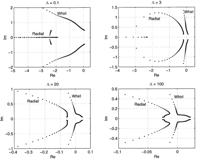
2-9 Minimum eccentricity for stability - Hydrodynamic water journal bearing . 44 2-10 Eigenvalue root locus in complex plane of hydrodynamic water journal bearings 45 2-11 Micro-bearing rig cross-section and schematic (Fr6chette [13]) . . . . 46
2-12 Schematic of axial and viscous forces acting on the rotor . . . . 48
2-13 Net axial force from water thrust bearings . . . . 49
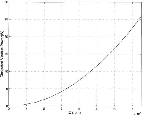
2-15 Dissipated viscous power for the water operation of the micro-bearing rig . 52 2-16 Micro-bearing turbine profile and velocity triangles for water operation at
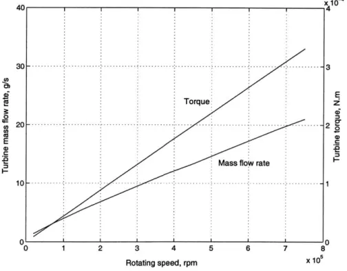
design speed w = 750,000 rpm. Velocities in the relative frame are primed. 53 2-17 Necessary mass flow rate versus rotating speed and corresponding torque for
water operation of the micro-bearing rig. . . . . 53
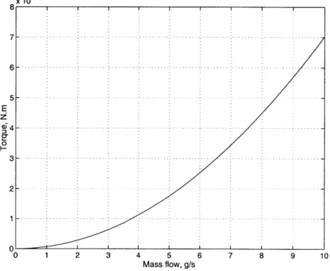
2-18 Turbine torque versus mass flow rate for a static rotor. . . . . 54
3-1 Photographs of the liquid bearing rig test set-up. . . . . 58
3-2 Photographs of the liquid bearing rig packaging. . . . . 59
3-3 Upstream part of the water handling system - courtesy of Chris Rakowski . 60 3-4 Downstream part of the water handling system . . . . 61
3-5 Photographs of the liquid bearing rig speed sensor set-up. . . . . 62
3-6 Speed sensor configuration propositions . . . . 63
3-7 Comparison of the optic fiber output for the four optical collimating systems 65 3-8 Comparison of the optic fiber output in its optimal configuration as used in the gas bearings experiments, and coupled to an achromat lens. Thick pyrex and quartz plates are inserted between the lens and the die to simulate a glass w indow . . . . 66
4-1 Packaging comparison - Left : Thrust bearings air flow at max gap - Right : Journal bearing air flow. . . . . 70
4-2 Capillary flow test. Comparison of experimental and model results for gas and liquid flow. Tests are run with die MCBR 6-7. . . . . 72
4-3 Thrust bearing liquid flow test. Comparison of experimental and model results. Tests are run with die MCBR 5-4. The rotor has not been released. 73 4-4 Thrust bearing water flow test at maximum gap. Comparison of experimental and model results. Tests are run with die MCBR 3-11. The rotor has been released . . . . 75
4-5 Rotor axial positioning test result from die MCBR 3-11. Comparison of experimental and model results for water flow. . . . . 76
4-6 Journal bearing water flow tests and Poiseuille model prediction. . . . . 77
4-7 Spin test of the liquid micro-bearing device 2-1. The device accelerates and then crashes. It is restarted, and accelerates up to 21,000 rpm. . . . . 80
4-8 Spectrogram for the water bearing accelerating to higher speed. . . . . 80 4-9 Operating line. Main pressure - speed relationship for die 2-1. . . . . 81
4-10 MOP operating line. MOP differential pressure - speed relationship. .... 82
4-11 Rotational speed and turbine inlet pressure for the journal bearing investiga-tion. Plateau of turbine inlet pressure are reached, during which the rotating speed is only a function of the journal bearing inlet pressure. . . . . 83
4-12 Rotational speed - journal bearing axial differential pressure relationship. . 83
5-1 Cross section of the micro-turbopump concept. Vertical dimension not to scale. 86
5-2 Exploded top and bottom views of the turbopump stack. 3D rendering re-alized by Diana Park. Vertical dimension not to scale. The horizontal sep-aration that appears on each layer comes from the rendering and is not representative of the design. . . . . 87 5-3 Initial concepts of the turbopump layout . . . . 90
5-4 MISES pump design and C, distribution . . . . 94
5-5 MISES nozzle guide vanes design and Mach number distribution. Symbols are defined in the nomenclature. . . . . 97 5-6 MISES turbine design and Mach number distribution. Symbols are defined
in the nom enclature. . . . . 97 5-7 Cross section of the turbopump concept. Definition of the regions for piping
losses. ... ... 98
5-8 Pressures on the front side of the rotor and back plenum. The pressures indicated are the design pressures for, respectively, the turbine inlet, the turbine exit, the pump exit, the pump inlet. . . . . 100 5-9 Thrust bearing flow and resistances model. Simplified configuration and
associated pressure distribution for the forward thrust bearing. . . . . 102
5-10 Turbopump gas journal bearing natural frequency . . . . 104
5-11 Turbopump drag versus speed. Drag occuring in the back plenum for design
speed versus depth of the plenum . . . . 105 5-12 Layout of the wafer. The mask illustrated corresponds to the front of wafer
3 (rotor). The boundaries are defined but the polarity is not shown. . . . . 108 5-13 Layout of turbopump wafer 1 . . . . 109
5-14 Layout of turbopump wafer 2 . . . . 109
5-15 Layout of turbopump wafer 3 . . . . 110
5-16 Layout of turbopump wafer 4 . . . . 110
5-17 Die-level images of turbopump wafers 2 (left - turbine exit plenum) and 4 (right -turbine inlet plenum). Images courtesy of Yoav Peles. . . . . 111
5-18 Left : wafer-level image of turbopump rotor wafer. Image courtesy of Yoav Peles. Right : SEM picture of turbopump rotor. . . . .111
5-19 Close-up images of the turbopump rotor showing the pump blades trailing edge (left) and the turbine blade leading edge and the journal bearing edge (right). . . . . 112
5-20 Cross-sectioned die . . . . 112
5-21 Top view of a cross-sectioned die, showing the water flow paths. . . . . 112
5-22 Bonded, die-sawed and pyrex anodically bonded turbopump die. . . . . 113
A-1 Hierarchy and function of routines in the incompressible thrust bearing sim-ulation . . . . 127
C-1 Capillaries flow experiments with the original setup. . . . . 144
C-2 Capillaries flow experiments with the second setup. . . . . 145
C-3 Thrust bearings gas flow experiments at maximum gap before and after water contamination. Die 2-12. . . . . 146
C-4 Thrust bearings gas flow experiments before and after water contamination. Rotor axial position tests. Die 2-12. . . . . 147
C-5 Thrust bearings water flow experiments at maximum gap after changing tubing with teflon. Die 3-12. . . . . 148
C-6 Die 5-4 aft thrust bearing water flow experiments with Teflon and copper feeding lines. . . . . 148
List of Tables
2.1 Thrust bearing geometry for the micro bearing rig . . . . 32
2.2 Micro-bearing rig turbine blades design parameters . . . . 47
2.3 Hydrostatic liquid bearings operating point . . . . 47
2.4 Comparison of the predicted performance of the micro-bearing rig geometry with gas and liquid . . . . 55
5.1 Advantages and draw backs of the turbopump cinfigurations . . . . 91
5.2 Turbine 1-D design results . . . . 96
5.3 Pressure losses in the turbopump at flow rates of 2.5 g/s . . . . 99
5.4 Pressure required in the aft plenum for axial balance at three speeds . . . . 101
Nomenclature
Roman
A Area, usually a cross-sectional flow area (m2
) C Chord (of a blade) (m)
CD Discharge coefficient
Cp Specific heat (J.kg.K)
D diameter (m)
Dh Hydraulic diameter (m)
F Force (N)
ITSP Specific impulse (s)
L Length (m)
M Mach number
M Non-dimensional mass (M) = mf72Lp2t P Pressure (Pa or atm or psi) and power (W)
R Gas constant and rotor radius (m) and resistance and turbine reaction S Stiffness (N.m)
T Temperature (K)
Wr Sommerfeld number Wr = I2" 2
c Celerity of sound (m.s-1) and bearing clearance (m)
dP Axial differential pressure (psi)
e Distance between bearing and journal centers (m)
f
Lens focal distance (m) and friction factorf/n
Lens focal numberg Acceleration of gravity (m.s-3) and thrust bearing gap (m)
h Target optical diameter or enthalpy or blade height (m)
h" Source optical diameter
I Length (m)
m Mass (kg) and optical magnification
rh Mass flow (kg.s- 1
)
r Radius (m)
s Distance lens -target
s"/ Distance source - lens
u Radial velocity (m.s- 1)
v Tangential velocity (m.s- 1
)
w Resultant load in a journal bearing (N)
Greek
A Non-dimensional bearing number A = 7
Q Rotational frequency (Hz)
Qn Whirl frequency (Hz)
H Pressure ratio
a Pump backsweep angle (rad)
13 Swirl angle
-y Specific heat ratio (gas constant), C,/CV
c Eccentricity ratio (axial or radial) Load parameter
(
= 'rEfficiency
A Wavelength
A Viscosity (kg.m~1.s-1)
7r Pressure ratio
#
Attitude angle (rad)p Fluid density (kg.m 3)
0 Shear stress (Pa)
T Temperature ratio
W Angular velocity (rad.s 1
) Clearance to radius ratio
4
= 'Subscripts
1 At the pump blades leading edge 2 At the pump blades trailing edge
P Pump
Po Pump exit
T Total
TBi At the thrust bearing inside (for an annular geometry)
TBo At the thrust bearing outside
a Ambient
atb Aft thrust bearing
b At the turbine blade trailing edge
c At the turbine blade leading edge
cap Capillaries
ftb Forward thrust bearing
in At the inlet inh Inherent ir Interrow min Minimum n Whirl orif Orifices r Radial rad Radial s Static sat Saturation
srad-in Static at the inlet of the radial gap area
t Tangential
tb Thrust bearings
Acronyms
1D one-dimensional
2D two-dimensional
3D three-dimensional
ATB Aft thrust bearing
CFD Computational fluid dynamics
DAQ Data acquisition system
DRIE Deep reactive ion etching
FTB Forward thrust bearing
JB Journal bearing
JPP Journal pressurization plenum
MCBR Motor compressor bearing rig
MEMS Micro electro mechanical systems
MOP Motor Outer Plenum
Chapter 1
Introduction
Made with the same silicon fabrication methods used to produce computer chips, micro-electromechanical systems (or MEMS) have over the last decade become well embedded in the high-tech landscape. MEMS offer large functionality and can offer a substantial cost advantage due to their fabrication technology. Current commercially exploited MEMS are low power, low energy devices, such as those used in automobile airbags, inkjet printers, pressure sensors.
A new class of MEMS devices, power-MEMS, have been investigated over the past
few years [4]. They are silicon fabricated energy conversion microsystems. High speed rotating machinery is required to achieve high performance and power densities equivalent to those in the best large-sized machines produced today. Single-crystal silicon offers excellent structural characteristics for such applications. Its high strength-to-density ratio enables high rotating speeds.
The focus of this work is to design a demonstration millimeter-scale liquid turbopump and investigate the behavior of liquid microbearings as an enabling technology required for a micro-rocket engine. The realization of power MEMS presents new challenges to traditional disciplines, and low friction fluidic bearings are required to support the rotor. The demonstration micro-turbopump designed and fabricated in the focus of this work is part of the proof of the feasibility of this pumping system.
This chapter first briefly describes the work on-going at MIT in the power MEMS area, and then discusses the turbopump motivation and objectives.
1.1
The MIT Micro Gas Turbine and Micro Rocket Engine
projects
Two power MEMS projects are on-going at MIT, referred as the Micro-gas engine and Micro-rocket projects.
The micro-engine concept was proposed in 1994 by Epstein et al. [3]. As shown in Figure 1-1, the baseline device is a centimeter-scale gas turbine engine for propulsion of Micro Air Vehicles or power generation. A demonstration micro-engine producing 10 grams of thrust was designed by Protz [34].
Starting Air In
I~
Compressor Inlet I PIL 3 Fuel InI3.7 mm
Exhaust \Turbine Combustor
Figure 1-1: Baseline design for the MIT microengine. Demo engine cross-section at two different radial locations, and 3D section of the demo engine. (Illustration courtesy of Diana Park)
The micro-rocket engine concept was proposed and investigated by London [26]. The complete system is illustrated conceptually in Figure 1-2. The rocket thrust is 15 N at a mass flow of 5 g/s and Ip, of 300 sec [26]. The three primary components of a microrocket system are the valves, the pressurization system, and the cooled thrust chamber. A six-wafer stack demonstration cooled thrust chamber has been designed, fabricated, packaged, and tested.
Valves Chamber Tupms 18mm Side C oling Passe ges Nozzle 29 m 2.9 mm 13.5 mm
Figure 1-2: Conceptual view of the location of the various micro rocket system components, and picture of the thrust chamber before bonding. (Illustration courtesy of Diana Park)
1.2
Micro turbopump for the rocket engine
In liquid propellant rocket engines, the propellant must be fed into the combustion chamber at a high pressure. The two general types of propellant feed approaches are gas-pressure and turbopump systems. A turbopump feed system uses pumps to pressurize the propellants. These pumps are driven by turbines, which are themselves driven by the expansion of hot gas. A turbopump feed system has been selected for the microrocket engine [5]. Turbopump feed systems differ in the cycle they employ. An expander cycle was chosen for simplicity
[33].
1.3
Motivation and objectives
Previous work on the micro rocket engine has focused on the cooled thrust chamber. Liquid valves have not yet been investigated. Preliminary investigation of the pumping system has been documented in [5, 33, 26].
The focus of this thesis is the turbopump. The required pressure at the inlet to the cooling passages and therefore at the pump exit is 300 atm. The primary objective of this work is to demonstrate the feasibility of the turbopump concept. To do so, a micro-scale turbopump producing a pressure rise of 30 atm for water has been designed. For this first design, the turbopump is not strictly considered as part of the rocket system but is rather
of proof-of-concept device .
Realizing such a device is a challenge for modelling and fabrication of high-speed turbo-machinery, high speed fluid bearings, and in modelling micro-scale cavitation. To demon-strate the technology necessary for the rocket turbopump, several main components were chosen for individual demonstration :
" a cavitation cascade: Pennathur [31] has focused on micro-scale cavitation modelling,
and experiments using a static cascade.
" liquid bearings: The integrated turbopump may require liquid bearings. One objective
of this thesis is to model and demonstrate liquid micro bearing operation.
1.4
Organisation of Thesis
This chapter has introduced the concept of a micro gas turbine engine and a microrocket engine, and motivated the development of a demonstration turbopump, including the in-vestigation of liquid microscale bearings.
Chapter Two describes the liquid bearing modelling effort. It addresses thrust and journal bearings. The behavior of an existing device, the micro bearing rig, in a liquid
environment is analyzed.
Chapter Three describes the experimental apparatus that was used to test the liquid micro-bearing devices.
Chapter Four presents the results of the liquid bearing experiments.
Chapter Five presents the overall system design and layout of the demonstration tur-bopump.
Chapter Six concludes the thesis. A summary of the research, the contributions and recommendations for future work on this area are presented.
Chapter 2
Bearings and Rotor Dynamics :
Theory
2.1
Introduction
The micro-gas turbine and micro-rocket engine turbomachinery require high rotational speeds in order to achieve high power densities. Low friction bearings are required to support the rotor against fluid forces, rotor dynamics, and externally applied accelerations while operating at speeds of the order of a million rotations per minute (rpm) . For the micro-gas turbine, gas film, electrical, and hybrid gas-electrical bearing concepts had been examined [28]. Gas lubricated bearings were selected on the basis of superior load bearing capability, low friction and relative ease of fabrication, and have been successfully operated
at high speeds [42].
A pair of thrust bearings support the axial loads on the rotor. A journal bearing supports
the radial loads.
To minimize technical risk, the micro-rocket engine project utilizes as much micro-engine gas turbine technology as possible, thus the same kind of bearing was selected. Since the micro-rocket runs with liquid propellants, both liquid or gas bearings could be used to sup-port the turbomachinery rotor. Since micro gas bearings have been explored in some detail
[28, 25, 42], this chapter examines the feasibility of using liquid bearings at this length scale.
Hydrostatic In the hydrostatic bearing, fluid is supplied from an external source to form
a lubrication film. The stiffness of the film is provided by the restoring pressure forces acting on the rotor, when displaced from equilibrium. Stiffness creation mechanisms are detailed in the following sections.
Hydrodynamic The hydrodynamic bearing is self-acting. The rotor system acts as a viscous pump: a pressure distribution in the bearing is obtained from the motion of the rotor. It can create stiffness to enable stable operation.
Both modes are considered herein. Special focus is given on liquid bearings that need to be investigated for the micro-rocket engine turbopump.
2.2
Thrust Bearings
The previous rotating devices designed and fabricated in the focus of the micro-engine project use a pair of hydrostatic gas thrust bearings as proposed by Lin [25]. The following sections describe the operation and the design parameters of these bearings. Liquid thrust bearings are then investigated. Operation of the micro-bearing rig with water is analyzed, and a liquid thrust bearing design is proposed. Wong [42] has recently demonstrated hy-drodynamic thrust bearings using a self-acting spiral groove design. This kind of bearing is not considered herein.
2.2.1 Hydrostatic thrust bearing operation
Pressurized fluid is supplied to a plenum. As described above, the stiffness creation mech-anism is linked to resistances to the flow, which entail pressure drops.
The fluid flows through two elements in series: a number of axial orifices (capillaries) and a radial outflow gap between the rotor and the stator as shown in Figure 2-1. As can be seen, the bearing total gap is defined as the sum of the distances between the front and aft sides of the rotor and their facing stator, and the axial eccentricity is the ratio of the rotor axial displacement from the center to half of the bearing total gap. The pressure drop results from the flow resistance of the capillaries, the turning of the flow from the capillaries into a much smaller gap between the stationery and rotating bearing members (inherent resistance), and the radial outflow resistance. The capillaries present a fixed resistance to
the flow. The radial outflow resistance varies with the axial eccentricity of the rotor. This variable resistance creates a restoring axial pressure force on the rotor [13]: a smaller gap results in a smaller flow, thus in a smaller pressure drop in the orifices where the resistance is fixed, and then in a larger pressure on the considered side of the rotor. The inherent resistance will increase with decreasing bearing gap, but its variation is smaller than the radial flow resistance if designed correctly [25].
The axial stiffness is computed from these restoring forces coming from both thrust bearings. Flow path Capillary resistance Inherent resistance Radial outflow resistance Pressure -+ profile total gap=2g rotor axial displacement = z axial eccentricity = z/g
Figure 2-1: Schematic of hydrostatic thrust bearings (from Frechette [13])
9
1-z
g+-2.2.2
Design parameters
The key design parameters of the hydrostatic thrust bearings are the capillary diameter D,
the length 1 and the bearing gap g. The rotor axial position is defined as axial eccentricity, which is axial displacement normalized by bearing gap.
The thrust bearing design goals are to maximize the axial stiffness, to obtain a sufficient load for balance, and to minimize the viscous drag.
The existing rotating micro devices were designed with a back plenum, so that the net axial load on the rotor at steady state is zero, without considering the action of the thrust bearings. The thrust bearings are intended to provide a restoring axial stiffness, which must overcome the destabilizing pressure forces or operation induced loads. The axial stiffness is maximal when roughly half the pressure drop occurs in the capillaries [13].
The thrust bearings must support a load large enough to overcome a change in pressure distribution during a transient (e.g., during a rotor acceleration). Yet, they do not support load at steady-state where the axial eccentricity is kept close to zero, but only supply stiffness. Therefore, a design goal is to maximize the load from the thrust bearings on the rotor at a 'limit' eccentricity1 . This load has to be larger than any force variation that might occur on the rotor during a transient.
Finally, the drag in the gap area has to be considered. The flow in this region can be modelled as a Couette flow.
Design parameter studies are conducted using a combination of flow restriction models developed by Jacobson [20]. The forces, stiffness and flow rates are calculated from the three resistances described in the previous section. This pseudo-compressible model was investigated as a focus of this thesis. It was automated to allow faster parameter analysis, and transformed both to an incompressible model for liquid thrust bearings analysis as describes in the following section, and to a fully compressible model by including the proper definition of compressible total pressure,
PT=Psx (1+ 21 xM2)-, (2.1)
instead of the sum of static pressure plus dynamic pressure, which is only valid at low Mach 'This limit eccentricity is the empirical border of the safe operating range. A value of 0.4 has been assumed here [20].
number. A detailed description of this model is given in Appendix A.
2.2.3 Liquid thrust bearings
Liquid hydrostatic thrust bearings were investigated, since they could be used in a micro-rocket engine turbopump. Analysis is performed considering a static rotor. The pressures involved in the thrust bearings are larger than atmospheric, and thus do not allow for cavitation. Thus, liquid thrust bearings differ from gas thrust bearings in terms of viscosity and compressibility.
An incompressible model was developed, using the same flow restrictions models as described in the previous sections. These models yield the following pressure distribution on the rotor (on one side) :
Psrad-in if r < r0
Ps =
Psradin - log(I-) if r"
<
r< ri
where Psradiin is the static pressure at the inlet of the radial gap area. The force on the rotor is obtained by integration of this pressure distribution.
Results for the micro-bearing rig geometry are presented hereafter. The micro-bearing rig geometry is detailed in Section 2.4.1, and the thrust bearing geometry is described in Table 2.1.
Stiffness and mass flow rate
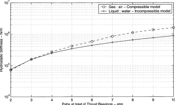
Figure 2-2 shows the axial stiffness derived from the thrust bearings in the micro-bearing rig geometry, and the corresponding total mass flow. These data are characteristic predictions, and not operating predictions, since they simulate a zero-eccentricity rotor, blocked in this position. Data for water are obtained with the incompressible model, and data for air with the fully compressible model. As can be seen, higher pressures are necessary in the liquid system to obtain the same stiffness as in a gas system, for a stiffness larger than 2.105N/m. This results in a much higher flow rate.
Both for liquid and for gas, the Reynolds number in the capillary is an order of magnitude higher than in the radial area. Second, at a given location, the Reynolds number in the gas bearing is an order of magnitude greater than in the liquid case. The pressure drop scales
Table 2.1: Thrust bearing geometry for the micro bearing rig
Forward thrust bearing Axial gap 1.5 pm
Number of orifices 14 Location of orifices 0.55 mm
Outer pad radius 0.7 mm
Orifice diameter 11 pm
Orifice length 100 pm Aft thrust bearing Axial gap 1.5 pm
Number of orifices 18
Location of orifices 0.55 mm
Outer pad radius 0.9 mm
Orifice diameter 11 pm
Orifice length 100 pm
with the Reynolds number, and the stiffness is associated with the variation in pressure drop in the radial area when the rotor is slightly displaced axially. Consequently, the gas and liquid systems behave differently, and there is no simple physical explanation for the stiffness differences. The velocities in the gas case are found to be two order of magnitudes larger than in the liquid case, which suggests that the mass flow should be an order of magnitude lower as verified.
Operating map
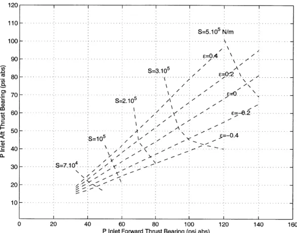
The operating map of the water thrust bearings was investigated. Figure 2-3 presents the iso-stiffness and iso-eccentricity lines for the micro-bearing rig rotor in equilibrium (i.e., the net force is zero) under the action of two water hydrostatic thrust bearings. Empirical data suggests a desired axial stiffness of 3.105N/m for high-speed operation [20]. Positive
pressure forces will develop on the front side of the rotor while spinning, because of the pumping pressure. Thus, a slightly positive axial eccentricity (of 0.1 to 0.2) is desired at equilibrium under the sole contribution of the thrust bearings, so that the rotor is axially centered during operation. As can be seen from Figure 2-3, these requirements lead to the
7
---1 0 . .. .. . .. .. . . . .. . .. . .. .. . .
... : -0 - G a;,:'air - C om pressible m ode
... ...
--i- Liquid: water - Incompressible mod]el
... ... ... ... ... ... ... ... ... ... E Q z 4E) 1 0 .. . . .. . . . .. ... . .. .. . ... . .. . .. . . . .. . .. . . .. . . .. .. . .. . . .. . .. ... . .... .. . .. . .. . .. . .. .. . .. . .. . .. . . .. .. . .. . .. . . .. . . .. . .. . . .. .. .. . .. .. . .. .. .. .. . ... . .... .. . .. . . .. . .. . .. .. .I .. . .. . .. . .. . .. . .. . . .. . . .. . . .. . .. . . .. ... .. . .. .. . .. .. .. . .. ... . .... .. . . . . .. . .. . .. CO . .. .. . .. . ...: ...: ... .... ... ... ... . . ... ... ... . ... ...: ...- .. . . ... ... ... ... ...0 , ... ... ... ... .. ... ... ... ... ... C/) ... ... ... ... .... ... ... ... 2 5 1 0 . . .. . . .. . .. ... .. . . .. . .. .. .. . .. ... . .. . . .. .. . .. . .. . .. .. . .. . .. . .. . .. . .. . .. . -. -. -.-. -. -. -.-. -. -.-. -.-. -.-. -. -.-. -.-. -. -.-. -.. .. . .. ... . .. . .. . .. . .. . .. . ... ... . .. .. . .. . . .. . .. . .. . . .. . ... . .. . . .. .. . . .. . .. . .. . .. . .. . . .. . .. . .. . .. . .. ( v .. . . .. . . ... . .... .. ... .. .. .. . . .. ... .. . .. .. . .. . .. . .. . .. ... . .... .. . .. . .. . .. . .. . .. . .. .. . .. .. .. . .. . .. . ... . .. . .. . .. . .. . .. . .. . . .. . .: . . .. . .. . . .. .: . . .. .. .. . .. .. .. . .. ... . .... .. . .. . .. . .. .. . .. . .. . .. . .. .. . .. . .. . ... . .. . .. . .. . .. . . . .. . . .. . . . .. . . . . .. . .. . .. . .. .. . .. . .. . .. . .. . .. . .. . .. . .. .. .. . .. . . .. . .. . . .. . . .. . .. .. . .. .. .. . .. . . .. . .. ... . .. . . .. .. . .. . .. .. . .. . .. . .. .. .. .. . .. . .. . .. . .. . .. . .. . .. . .. . .. . . .. . .. . .. . . .. . .. .. . .. .. .. . .. .. .. . .. ... . .. .. . .. . .. . .. . .. .. . .. . .. . ... . .. . .. . .. . .. . .. . .. . . .. . ... . .. . . .. . .. ... . .. .. .. . .. . .. . .. - - . .... . .. .. . . .. . .. . .. ... .* . . .. . . . .. . .. . .. . .. 10 41 2 3 4 5 6 7 8 9 10
Pabs at Inlet of Thrust Bearings - atm
1 0 - ... ...I ...I ... ... ... G as : air - C om pressible m odel
... ... ... ... ...
... I ... Liquid : water - Incom pressible model
... ... ... ... ... ... ... ... ... ... ... ... - 2 .. . . .. .. . .. ... . . ... . .. . .. . .. . . .. . .. . .. . .. . .. . .. .. . .. . ... . .. . . .. ... . . ... . .. . .. . .. .. .. . .. . .. . .. .. .. .. . .. . .. . ... . .. 1 0 . .. . . ... ." ' ' * * * .. .. . . ... .... ... ... ...I ... ... ...I ... ... ... .... ... ... ... ... ... .. ... CO ... .... ... ..I ... ...I ...: ... C E ... ... ... ... ... ... ... ... ... ... ...: ... ... .. ... ... ... ... ... .. ... ... ... .. .. ... CO ... ... CU CO 1 0 7: .. . .. . . . .. . .. .. . .. .. . .. ... . . ... . .. . .. . .. . . ... . .. ... . .. .. .* . .. . .. . .. . .. ... . . ... . .. . .. . .. . . .. . .. . .. . .. .. .. . .. .. . .. . ... . .. . .. . .. . .. . . .. . . .. . .. .. .. . . .. .. .. . .. . . .. .. . .. ... . . ... . .. . .. . .. . .. .. . .. . .. . .. .. .. . .. .. . .. . ... . .. . .. . .. . .. ...... ... ... ..... * ... ...... ... ... ...... ...... : ... ... ... ... ... ... ... ... ... ... ... ... ... ... ... ... ... ... ... ... ... 10-4 2 3 4 5 6 7 8 9 10
Pabs at Inlet of Thrust Bearings - atm
Figure 2-2: Hydrostatic thrust bearings characteristics for a fixed centered rotor for water and air
following operating range for the 120 110 100 Ca) .0 a) CO (D ClS a. 90 80 70 60 50 40 30 20 10 0 thrust bearings :
Pforward E [90psi, 95psi]
Paft E [50psi, 60psi]
20 40 60 80 100
P Inlet Forward Thrust Bearing (psi abs)
120 140
Figure 2-3: Stiffness S and eccentricity E for a rotor in equilibrium with hydrostatic water thrust bearings (pressures forward and aft are different because the thrust bearing design is not symmetric)
Stability analysis
Finally, a stability analysis of these liquid thrust bearings was performed. When the pressure of one thrust bearing is modified, the rotor moves to a different equilibrium position. In other words, the system has to be able to present a net load to oppose the net force due to this pressure change. This must be achieved with a small variation of axial eccentricity to maintain the axial position in the safe range.
S=5.105 N/rn =0.4
~
S=3.105 71 -- -4/ S=2.10---- -4 ....... .. . .. . . . .. .V .. ... .~6 .. .- . . .. . . . . .. . . 4 V7...
. 0
...
S=
. . . .
...
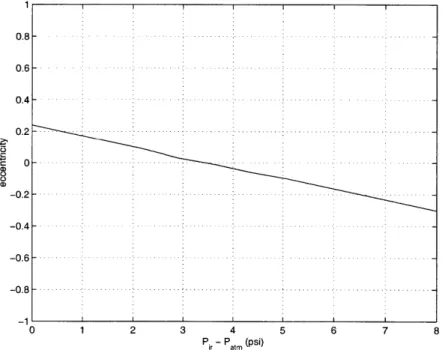
. . . . ..0. . . /.. .. .... .. .. . .. . . .. . . . ... ... ... ... 160Figure 2-4 shows the predicted equilibrium eccentricity versus the pressure of one thrust bearing, while the pressure at the inlet of the other thrust bearing is constant. As can be seen from the flat shape of the curves, a moderate change in pressure results in a small change of eccentricity to maintain stability. Starting from an equilibrium position where
Patb = 4atm ~- 60psi and Pftb = 6atm ~ 90psi, a change of 0.5atm in the aft or forward
thrust bearing pressure is overcome by a variation in eccentricity of 0.10 to 0.135. This allows safe operation for the rotor, considering the safe eccentricity range is assumed to be
[-0.4 to 0.4]. -I- Pftb = 4 atm -E- Pftb = 6 atm 0.5-0.5 CD) U - 1 1 2 3 4 5 6 7
Aft TB Pressure - atm
-i- Patb = 3 atm
-e- Patb = 4 atm
0
.5
--1
2 3 4 5 6 7 8 9
Forward TB Pressure - atm
2.3
Journal Bearings
2.3.1 Introduction
This chapter deals with plain cylindrical journal bearings, where the bearing surfaces are parallel to the axis of rotation. Journal bearings are used to support shafts by carrying radial loads with minimum power loss and minimum wear. The journal bearing consists in a lubricant film trapped between a plain cylindrical sleeve (the bearing or stator) and the rotating shaft (the journal or rotor), as presented in Figure 2-5. The journal spins at an angular velocity w inside the bearing.
The shaft does not normally run concentric with the bearing. The displacement of the journal center relative to the bearing center is the eccentricity e. The average gap between the journal and the bearing is the clearance c. The eccentricity ratio e is the ratio of the eccentricity to the clearance c. The attitude angle q is the angle between the line of centers that joins the bearing center and the journal center, and the load applied to the journal.
bearing
load
- - bearing center'
journal center R
journal
Figure 2-5: Journal bearing geometry and nomenclature
Liquid journal bearings, both hydrostatic and hydrodynamic, have been investigated. The geometry considered is that of the micro-bearing rig, developed for gas bearings exper-iments. The journal bearing of this device falls outside of the classic design space because of the large gap-to-radius ratio c/R, the small length-to-diameter ratio, the high Reynolds number, and the large surface area compared to the mass of the rotor [4].
2.3.2
Hydrostatic Journal Bearings
Hydrostatic bearings are externally pressurized and should be distinguished from hydrody-namic bearings, which are self-acting. In a hydrostatic bearing the surfaces are separated by a film of liquid forced between them under pressure. The pressure drop across the bearing supports the load. The pressure is derived from an external source. Because the pressur-ized film is not produced by the relative motion of the bearing surfaces, a complete film is present whenever the bearing is pressurized, even at zero speed [36]. The load-carrying capacity is independent of bearing motion and lubricant viscosity [18].
In practice, this bearing should be described as 'hybrid'. Indeed, the applied force on the journal will be reacted by the combined effect of hydrodynamic and hydrostatic bearing film pressures as soon as the shaft is rotating.
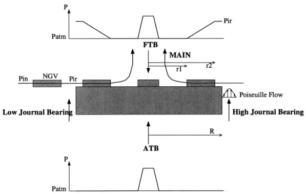
The gap is pressurized from a plenum that sits below both the rotor and the stator. The fluid flows axially, forced by a pressure differential dp between the plenum and the inter-blade row region. Wong [42] and Orr [28] provide insight in the previous work on axial through-flows and hydrostatic stiffness modelling. Orr proposes one explanation for the ex-perimentally observed compensation mechanism. In reducing the Navier-Stokes equations to the Reynolds equation, inertia is neglected, and pressure-driven flows are assumed to be fully developed. The inertial effect of the growth of side-walls boundary layers at the entrance of the journal bearing is advanced to explain radial stiffness [28]. The hydrostatic natural frequency given by this model is in good agreement with the literature. Comparison of this model to the Tang-Gross model was performed by Wong [42]; he found that they differ by 15% for an axial pressure differential of 5 psi.
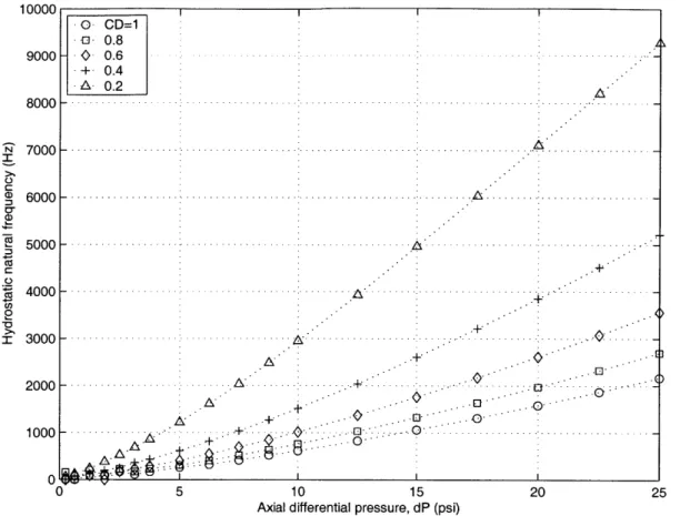
An incompressible model was developed by Breuer to account for this 'entry length' effect (the entry length being the distance needed for the flow to become fully developed). Figure 2-6 gives the hydrostatic natural frequency resulting from the axial flow driven by the pressure difference dp. A discharge coefficient CD is set to account for the resistance to the flow. It is generally accepted that a realistic value of this coefficient is between 0.4 and 0.7 for a sharp edge geometry [20].
10000 9000 8000 a) a) W Ca CD, 2 7 0 0 0 - -.-.-.-.-.-.-.- .- .- .- . 6000 - -.-..- - .. -5000 -4000 3000 2000 1000 0 5 10 15
Axial differential pressure, dP (psi)
20 25
Figure 2-6: Hydrostatic incompressible natural frequency for the micro-bearing geometry as calculated with the Tang-Gross model implemented by Breuer.
and Q, is the whirl frequency. Subcritical operation refers to a whirl ratio smaller than 1, supercritical operation refers to a whirl ratio greater than 1. Larson and Richardson
[35]
state that stable operation is possible up to a whirl ratio of 5 to 6 for gas journal bearings. Wong [42] measured whirl ratios of 10 in high-speed micro-bearing operation.
Recent calculations performed by Dr Yifang Gong [16] suggest that the hydrostatic journal bearing mechanism comes from an inherent restrictor effect at the inlet to the journal bearing rather than from a boundary layer development mechanism as previously thought. This being the case, the stiffness developed will strongly depend on the geometry of the journal bearing at the entrance. High stiffness requires that the walls have sharp corners at the entrance. This effect is currently investigated.
0- CD=1 - 0.8 - 0.6 + 0.4 A 0.2 -.-.-.-.-.-.-.- - .-- -- A -- A ..-.-- - - .- .. *.. . . . . . ..-. A. . A +--+-0 .. . .. .. .. .. ..
2.3.3 Hydrodynamic Journal Bearings
A hydrodynamic journal bearing relies on shaft motion to generate the load-supporting
pressures in the lubricant film. This bearing is said to be 'self-acting' because the hydrody-namic pressures which separate the two bearing surfaces are generated as a consequence of the movement of the bearing surfaces. The stiffness is derived from a moving surface acting as a viscous pump, but a non-zero eccentricity is required for stability. The surface of the journal drags liquid by means of viscous forces into the converging gap region between the two bearing surfaces. The result of the liquid being dragged into a more confined region is to create a back pressure. The squeeze mechanism of pressure generation provides a cushioning effect when the bearing surfaces approach each other.
Traditional approach
Pressure distribution in the film is modelled by Reynolds' equation which, with the shear stress at the journal surface, permits us to obtain the contact forces on the journal.
The assumption underlying the derivation of the Reynolds equation from the Navier-Stokes equations is violated in principle in the micro-bearing case, since the high Reynolds number results in non-negligible inertia effects in the bearing gap. Full Navier-Stokes com-putation results were compared to Reynolds lubrication solutions. The results showed that over the interesting range of bearing numbers, the Reynolds equation solutions remain ac-curate when compared to Navier-Stokes calculations [12].
The analytical solution of the Reynolds equation for the plain cylindrical journal bear-ing is known as the full Sommerfeld solution [18]. The pressure distribution is given by the following equation, in a non-dimensional form.
P
- Po (c 2 6E sinq5.(2 + Ecos#) (2.2)
pw r (2 + E2).(1 + e cos 0)2
In Equation 2.2, p is the local absolute pressure, po is the supply fluid pressure, called ambient pressure, and
#
describes the running angular position in the bearing.For an incompressible fluid, the full Sommerfeld solution is inherently unstable since the bearing has only cross-stiffness.
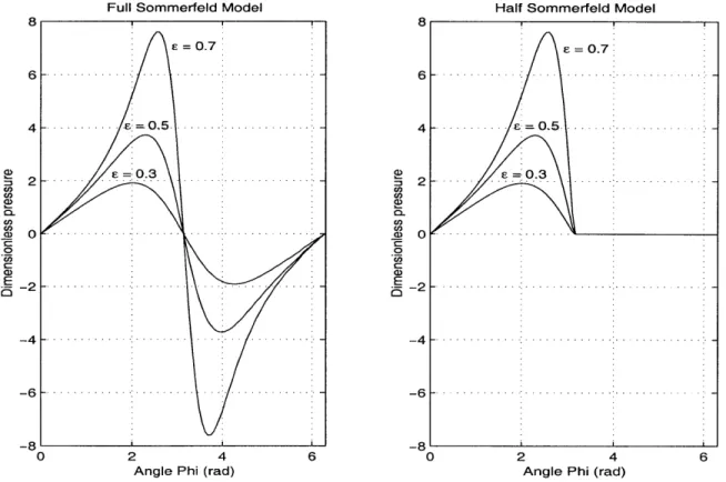
The Sommerfeld solution shows that the pressures in the divergent film are all lower than ambient pressure. Whenever the pressure falls below the saturation pressure, cav-itation occurs. In traditional bearings, the saturation pressure is similar to the ambient pressure surrounding the bearing, then the gas liberation maintains the pressure in the divergent clearance space at close to the ambient level [18]. This approach is known as the
Half-Sommerfeld solution. The analysis is restricted to the convergent film. Subambient
pressures predicted by the analysis should be ignored. The pressure distribution is then given by
P-PO p()( 2 _ 6csin q.(2+f cos0)
p _ pw r (2+E 2 ).(1+f cos )2 0 if 0 < q < ir if r
<
<
27rThe pressure distributions for both Sommerfeld solutions at different values of the ec-centricity ratio are presented in Figure 2-7.
Full Sommerfeld Model 8 E = 0.7 6 4 - -. - 0,5 0 -. - 2 -- .-.-.-.-.-. -4 - - - --- 6 .- --- --0 2 4 6
Angle Phi (rad)
U) 0. a E 8 6 4 2 0
Half Sommerfeld Model
S = 0.7 - - E= 0.5-E=0.3 -. . . . .. .-. - - - - .. ..-. - . ..- . .- .. -. -. -. -. -...-. . . ..-.. .. .-. -.. . -- . . .. . . . .. . . .. . . .-.. . . -21 -4 -6 -8 0 2 4
Angle Phi (rad)
Figure 2-7: Pressure distribution from the Full and Half Sommerfeld solutions
Stiffness and damping coefficients can be obtained analytically, and then a stability analysis can be conducted.
(D CL, CD) .0 E 6
New approach
Stability analysis were conducted, considering the Half Sommerfeld solution. The simple form of the pressure distribution allows an analytical calculation of the stiffness and damping coefficients, performed in [18]. The governing equation of the system can be reduced to a first-order differential equation, and thus solved by eigenvalues analysis.
This approach is valid as long as it is valid to consider that half the fluid region is cavitating. This assumption is usually valid since the ambient pressure in most bearings is similar to the saturation pressure of the fluid [18]. In a pump for the micro-rocket engine, it is possible that the journal bearing is supplied with high-pressure liquid. In this case, the previous assumption is not valid since the ambient pressure is much larger than the vaporization pressure.
A new stability model is proposed, where the cavitating region is more accurately
mod-elled, if it exists. For each value of the bearing number A (which is a non-dimensional form of the speed), an iterative scheme on the eccentricity is run. At each step, the pressure distribution is computed. The vaporization pressure is neglected compared to the ambient pressure, then its non-dimensional form is a function of the speed (or of the bearing number) and the ambient pressure:
Psat = (2.3)
If Psat > Pmin, there is no cavitating region. The exact solution is the Full Sommerfeld
solution, and the bearing is unstable.
If there is a cavitating region (necessary for stability), its boundaries
#1
and 02 are calculated. They verify the equation P(01) = P(02) = Psat, and then are obviously function of F. The new pressure distribution is then
-_ -2 (2 ) (+c 2 if
0
< # < q1 and #1 < 5 < 27rPsat if 01 < # < #2
The resultant load is computed. Following the notation adopted in [18] and detailed in the nomenclature, the resultant load is w, = '2+ w'2 where
='
f
pr sin(7r -#)
d# (2.4)0/27r
Wz = pr cos(7r -
#)
d# (2.5)=0.7 6-4 _ - E= 0.5 20.3 (D CL 0 -. - -- --. .. .. ... . . ... . -. . 0 a) E -2- P -tAp) -2 - - - - -- - s-( ) --4-. -6 -... -8 0 1 2 3 4 5 6 Angle $ (rad)
Figure 2-8: Pressure distribution from the new hydrodynamic model
The Sommerfeld number W, and the attitude angle D are calculated. Damping and stiffness coefficients can then be obtained, and a eigenvalue analysis is performed to deter-mine the stability of the system. This analysis is similar to the one conducted by Savoulides
[37] and is not detailed hereafter.
Results
In this new hydrodynamic stability and load prediction model, the Sommerfeld number and the attitude angle are calculated considering the cavitation region that depends on the supply pressure PO, the rotating speed w, and the eccentricity c.
The performance of the micro-bearing rig geometry was computed using this model, using water as fluid. The minimum eccentricity for stability is plotted in Figure 2-9 in the
(A, () plane, and in the (A, E) plane, and for two values of the ambient pressure surrounding
the bearing (average, or supply pressure). As can be seen, two stability boundaries exist, related to two different physical phenomenon. Hydrodynamic journal bearing stability requires stability for both these two phenomenon, the Full Sommerfeld instability, and the whirl instability.
At low rotational speeds (low bearing number A, below 0.1), stability is very difficult to achieve because a cavitation region only happens at eccentricities close to 1. The Full
Sommerfeld instability is the limiting factor; the model behaves very closely to the Full Sommerfeld model in terms of stiffness and damping.
As the speed increases (0.1 < A < 1.2 for Pa=30atm, 5 for Pa=latm), the saturation pressure in its non-dimensional form increases, then the minimum eccentricity required for stability decreases, the bearing cavitates at lower eccentricities.
At higher speeds still (A > 1.2 for Pa=30atm, 5 for Pa=latm), a different physical phenomenon becomes the limiting factor. A large cavitation region exists since Psat is small, and the behavior is now closer to that of the Half Sommerfeld model. In this model, the minimum eccentricity required for stability increases with the bearing number. This is a characteristic of the Half Sommerfeld incompressible model [18]. A rotor whirl instability develops, and a larger eccentricity is necessary for a larger stiffness. Whirl is a self-excited vibration in a journal bearing which is caused by forces inherent in the hydrodynamic lubricant film [22].
Finally, the stability boundary asymptotes to a constant eccentricity ratio of 0.762, which is a characteristic of the half-Sommerfeld model.
As can be seen in Figure 2-9, the whirl instability boundary appears at lower speeds when the pressure is raised. For a given speed, a bearing surrounded by a higher pressure liquid needs a higher eccentricity to run stably. Indeed, higher ambient pressure is equivalent to a more massive journal from the mass parameter M0= mPaip//72LM2 (terms are defined in the nomenclature). When whirl is the limiting stability factor, higher pressure journal then requires more load, i.e. more eccentricity, to run stably.
For a better understanding of the cause of instability, an eigenelements analysis was performed. Figure 2-10 presents the locus of the eigenvalues of the matrix describing the motion of the bearing, in the complex plane, for several values of A. There are two couples of complex conjugate eigenvalues, corresponding to two physical modes of vibration. A detailed analysis of the eigenvectors shows that one mode is a radial mode, it is associated to vibrations in the radial direction, whereas the other mode is a whirling mode. As can be seen on Figure 2-10, the mode associated with rotor whirl produces a Hopf bifurcation at all speeds (the real part of the eigenvalue changes sign). The radial mode does not produce a Hopf bifurcation at any speed. This is the second major difference from gas journal bearings. Liquid hydrodynamic journal bearings do not exhibit radial instability, at any speed or eccentricity.