Publisher’s version / Version de l'éditeur:
Congress of International Council of the Aeronautical Sciences (ICAS 2010), pp.
1863-1872, 2010-09-24
READ THESE TERMS AND CONDITIONS CAREFULLY BEFORE USING THIS WEBSITE.
https://nrc-publications.canada.ca/eng/copyright
Vous avez des questions? Nous pouvons vous aider. Pour communiquer directement avec un auteur, consultez la
première page de la revue dans laquelle son article a été publié afin de trouver ses coordonnées. Si vous n’arrivez pas à les repérer, communiquez avec nous à [email protected].
Questions? Contact the NRC Publications Archive team at
[email protected]. If you wish to email the authors directly, please see the first page of the publication for their contact information.
This publication could be one of several versions: author’s original, accepted manuscript or the publisher’s version. / La version de cette publication peut être l’une des suivantes : la version prépublication de l’auteur, la version acceptée du manuscrit ou la version de l’éditeur.
Access and use of this website and the material on it are subject to the Terms and Conditions set forth at
Advanced damage tolerance and risk assessment methodology and
tool for aircraft structures containing MSD/MED
Liao, Min; Bombardier, Yan; Renaud, Guillaume; Bellinger, Nick
https://publications-cnrc.canada.ca/fra/droits
L’accès à ce site Web et l’utilisation de son contenu sont assujettis aux conditions présentées dans le site
LISEZ CES CONDITIONS ATTENTIVEMENT AVANT D’UTILISER CE SITE WEB.
NRC Publications Record / Notice d'Archives des publications de CNRC:
https://nrc-publications.canada.ca/eng/view/object/?id=a4b0d03f-fbad-44af-9bb8-3f1b59b94017 https://publications-cnrc.canada.ca/fra/voir/objet/?id=a4b0d03f-fbad-44af-9bb8-3f1b59b94017
27TH INTERNATIONAL CONGRESS OF THE AERONAUTICAL SCIENCES
Abstract
This paper presents results from NRC’s development of advanced damage tolerance analysis (DTA) and risk assessment methods and tools for aircraft structures, including build-up structures containing multi-site fatigue damage (MSD) and multi-element damage (MED), to support the Canadian Forces (CF) aircraft structural life cycle management. The DTA methods developed include new closed-form solutions and generic finite element (FE) based tools to calculate the stress intensity factor (SIF) and the β-solutions for build-up structural configurations. To facilitate the risk assessment, an in-house crack growth analysis program, CanGROW, was developed to simultaneously grow multiple cracks. Guidelines were established to calculate the residual strength of MSD/MED structures using global and/or local FE models, considering load redistribution among adjacent components. For the MSD risk analysis, an efficient Monte Carlo simulation technique was developed to determine the crack size distributions at different inspection intervals, which were then used in NRC’s risk analysis code ProDTA to calculate the single flight hour probability of failure. Case studies on critical locations of the CC-130 centre wing structure are presented to demonstrate the capability of the developed methods and tools.
1 Introduction
The National Transport Safety Board (NTSB) investigation of a catastrophic failure of a C-130A during a firefighting mission in Walker, California, in 2002, concluded that the accident
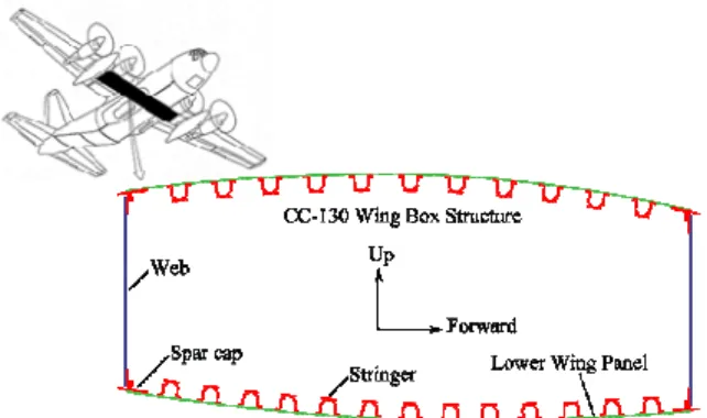
was caused by structural failure of the centre wing [1]. A detailed inspection of the failed area revealed multi-site fatigue damage (MSD) and multi-element damage (MED) in one of the lower surface panels of the centre wing. After this accident, the Canadian Forces (CF) launched a series of investigations to determine the fatigue lives of the centre wing structures (Fig. 1) of the CF CC-130 fleet. With the adoption of a Record of Airworthiness Risk Management (RARM) process by CF to manage the technical and operational airworthiness of all their aircraft, NRC was tasked to carry out quantitative risk assessment (QRA) of the CC-130 centre wing structure with MSD/MED. For such complex problems, advanced DTA and risk assessment methods are needed.
Fig. 1. CC-130 centre wing box
Extensive research has been carried out on MSD and widespread fatigue damage (WFD) since the Aloha accident in 1988. A brief survey of available MSD/WFD analysis guidelines and methods was performed at NRC by focusing on the major aircraft authorities and manufacturers [2]. Some useful technical guidelines were found in working documents from the Airworthiness Assurance Working Group
ADVANCED DAMAGE TOLERANCE AND RISK
ASSESSMENT METHODOLOGY AND TOOL FOR
AIRCRAFT STRUCTURES CONTAINING MSD/MED
Min Liao*, Yan Bombardier*, Guillaume Renaud*, and Nick Bellinger*
* Institute for Aerospace Research (IAR), National Research Council Canada (NRC)
(AAWG) [3] and the Federal Aviation Administration (FAA) for MSD/WFD evaluation [4]. The Monte Carlo simulation approach was found to be commonly used for MSD/MED evaluation. On the subject of risk assessment, it was acknowledged that additional studies would need to be conducted to establish a risk assessment approach, as it might apply to managing MSD/WFD situations [3].
To support CF fleet management using the RARM process, NRC developed advanced DTA and risk analysis methods/tools, aiming for not only the complex MSD/MED problems, but also for generic aircraft structure damage tolerance analysis (DTA).
2 MSD Damage Tolerance Analysis 2.1 Framework overview
A deterministic fracture mechanics framework was developed to carry out MSD DTA by determining the stress intensity factor (SIF) for multiple crack tips, propagating multiple cracks simultaneously, and calculating the residual strength (RS) of components possibly containing MED. For a probabilistic risk assessment, the framework is expanded with Monte Carlo simulations, which constitutes one of the main challenges for MSD/MED risk analyses, i.e. the lengthy computational time. For instance, performing 106 one-minute crack growth simulations (including multiple cracks and retardation modeling) requires almost 2 years of computational time on a regular personal computer. For this reason, numerical approaches involving the direct computation of the SIF solution using boundary and/or finite element (FE) methods were excluded in favor of the superposition and compounding of closed-form and tabular solutions.
2.2 NRC β-Factor Library
A library of β-factors [2, 5] was developed to conduct DTA of structures with or without MSD/MED, including new solutions developed to consider radial and equal/unequal diametrical cracks at an offset open loaded hole [6], an edge crack through a hole, link-up of two diametrical
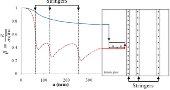
cracks, a crack approaching a hole, crack interactions, and a quarter circular corner crack at a hole [7]. Recently, the Poe’s β-factor [8] for a crack in a stiffened panel was largely improved by including fastener flexibility and arbitrary stringer locations. For example, the improved β-factors of a crack growing beside three stringers is shown in Fig. 2. The β-factor of the crack tip growing towards the stringer (right tip) is shown to be significantly reduced by the presence of the stringers while the crack tip growing away from the stringers is marginally affected. This new solution can be used to calculate the SIF of cracks in a wing box structure with stringers and spar caps without conducting FE analyses.
Fig. 2. β-factors of a crack growing in an infinite plate with arbitrarily located stringers
2.3 NRC Generic FE-based Beta Tool
The DTA of many aircraft structural locations also require β-factors that may not be accurately or practically estimated by closed-form or tabular solutions. These β-factors usually represent configurations with load transfers to adjacent structures, non-planar crack paths, complex boundary conditions, and irregular 3D geometries. In order to be compoundable with the closed-form or tabular solutions included in the NRC β-factor library, an FE based method was developed to obtain the β-factors corresponding to the effect of the special/complex features to be considered. In details, these factors are determined by taking the ratio, at different crack lengths a, between the SIF (K) obtained from a StressCheck FE model including the considered feature(s), and a base model without the feature. To ensure
Stringers Stringers
ADVANCED DAMAGE TOLERANCE AND RISK ASSESSMENT METHODOLOGY AND TOOL FOR AIRCRAFT STRUCTURES CONTAINING MSD/MED
compatibility, the loading, geometry, and boundary conditions used in the base model have to be identical to those used in the solutions provided by the β-factor library. Mathematically, the isolated effect of the special/complex feature(s) on the crack tip SIF, referred to as βf, is expressed as,
f Tb f Tb Tb Tf b f a a a a K K β π σ β π σ β β π σ β π σ β = = = (1)
where subscripts T, f, and b refer to “total”, “with feature”, and “base model”, respectively. The simplified FE models were designed to obtain Kf and Kb by disregarding the features
taken into account by the closed-form and tabular solutions, such as part-through cracks, holes, and pin loading.
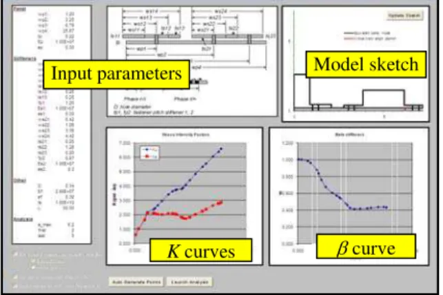
A quick survey indicated that most CC-130 centre wing fatigue critical locations can be represented by five typical configurations. To take advantage of this grouping, the FE models developed for those locations were parameterized and automated. To date, three parametric models were developed by NRC: 1) a cracked panel stiffened by a cap and a stringer, 2) a panel cracked at an integral stringer, and 3) a cracked L-shaped cap attached to a web and a wing panel. These models were packaged as MS-Excel tools [10] that can automatically manage the StressCheck FE analyses and generate β-factor curves. A screenshot of the tool is shown in Fig. 3 for a typical stiffened crack panel case, defined by a set of 32 geometric and material parameters.
For the analyses involving MSD/MED, the crack(s) can be allowed to grow over a large portion of the damaged component while the adjacent elements can be damaged. A significant fraction of the load can therefore be transferred into adjacent structures that are normally not considered by the local FE model and conventional SIF solutions. In such cases, a load reduction factor needs to be calculated for estimating the local load variation as the crack propagates. In this paper, this was done by simulating crack growth in a global model of the aircraft and by estimating the load that is diverted away from the local model area. Also,
the occurrence of MED, broken stringers in this case, was accounted for in the load reduction factor by disconnecting the appropriate elements in the local and global FE models. To ease crack growth analysis, the load reduction factor was expressed as a special β-factor. The effect of adjacent structures, combining the load reduction determined from the local and global models for the CW-1 location (Section 4.1), is presented in Fig. 4. In this case, two stringer failures (MED) were assumed along with a long panel crack growth.
Fig. 3. Screenshot of the generic FE-base beta tool for a stiffened panel configuration
0 0.2 0.4 0.6 0.8 1 1.2 0 50 100 150 200 250 300 350 400 450 500 550 βf
Lead crack length (mm) All stringers intact Stringer 1 failed Stringers 1 and 2 failed
Fig. 4. Example of βf representing adjacent
structural effects for CW-1 with MED
2.4 MSD Crack Growth Modeling
A special crack growth analysis program, CanGROW, was developed at NRC for MSD evaluation. CanGROW has the capability to grow multiple cracks simultaneously and to calculate the SIF by compounding a set of β-factors from the β-factor library and/or the FE
β curve
K curves
Model sketch Input parameters
Cap Stringer Stringer
based β-factor tool. Given the complexity of MSD crack growth modeling, an automatic compounding algorithm [2,5] was developed to identify and update the crack information, which includes extracting the location and size of a crack, determining if the crack is an edge or a centre crack, if the crack is a part-through or a through-thickness, defining the interactions with adjacent structural elements (edge, hole, or other cracks), verifying if crack link-up occurs, and merging the cracks as required (Fig. 5). The algorithm was designed such that the user has to define only the geometry of the cracked component (width, thickness, hole position/diameter), the loading (including bypass and bearing stress ratio), the initial crack sizes, and the special β-factors. The SIF of the
crack tip i, K , is calculated using the i
compounded total β-factor ( T i β ) as,
∏
= = = n j j T i i T i i a K 1 ,β β π σ β (2)where each βjmodels a single effect, such as a radial crack at a hole, the presence of adjacent cracks (i.e. crack interactions) and/or stringers, or the part-through quarter-circular corner crack.
Fig. 5. MSD crack scenario
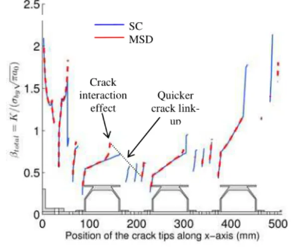
The MSD crack growth capability can be used to analyze the standard crack (SC) scenario, illustrated in Fig. 6, as defined in the damage tolerant design handbook [9]. The β-factors of the lead crack for the SC and MSD scenarios of the CW-1 problem (Section 4.1) are presented in Fig. 7.
Fig. 6. Standard crack (SC) scenario
For generic aircraft DTA purposes, CanGROW was expanded to simulate the SC scenario using a pre-defined sequential crack growth analysis method, referred to as a
phase-by-phase (PBP) simulation, which allows the user to compound different β-factors for different phases. For the example shown in Fig. 8, the total β-factor for phase I was obtained by compounding the radial crack solution with the quarter circular corner crack effect. The effect of MED can also be included using the special β-factors.
Fig. 7. β-solutions of the lead cracks for the SC and MSD scenarios
Fig. 8. Example of SC crack growth simulation in a panel with holes
Furthermore, CanGROW was enhanced with a module to back calculate the equivalent initial flaw sizes (EIFS) from the in-service findings, and a module to carry out a Monte Carlo simulation on crack growth using random initial crack sizes. Another module for non-destructive inspection (NDI) simulation is under development.
2.5 MSD/MED Residual Strength Analysis
The residual strength (RS) of the cracked structure is calculated using the fracture toughness (Kc) criterion, the net section yield
(NSY) strength criterion, and a plastic zone link-up (PZL) criterion [11]. The MSD and MED effects are included in the compounded β-solutions, which are in turn used to determine the residual strength based on the Kc criterion.
Crack interaction effect Quicker crack link-up SC MSD
Lead crack Secondary crack
Hole
Plate Lead crack Secondary crack
Hole
ADVANCED DAMAGE TOLERANCE AND RISK ASSESSMENT METHODOLOGY AND TOOL FOR AIRCRAFT STRUCTURES CONTAINING MSD/MED
For built-up structures, a FE-based global load reduction factor is also used in the NSY criterion of the cracked component. For PZL, the flow stress, i.e. the average of ultimate strength and yield strength of the material, is used to calculate link-up between two adjacent cracks, or between a crack and a hole or an edge. The combined RS curve is obtained by taking the minimum of the RS values from the multiple criteria, including the possible link-ups, and by applying a set of guidelines to make the final RS curve continuous and monotonically decreasing. An example of this process is illustrated in Fig. 9 for two cracking scenarios obtained for the CW-1 location (Section 4.1). In this case, an operational limit stress was also applied and the RS was normalized to this limit stress. 0 0.2 0.4 0.6 0.8 1 1.2 0 50 100 150 200 250 300 350 400 450 500 550 N o rm a lize d σRS
Lead crack length (mm) SC scenario MSD scenario Kc MSD
Kc MSD (through crack only) NSY
Note: For clarity,PZL curves are not shown on this graph
Fig. 9. Residual strength curves for CW-1: SC and MSD scenarios
3 Risk Assessments for Aircraft Structures With/Without MSD/MED
3.1 Methodology and Tool
Risk based management approaches/tools have been adopted by many military air fleets. In the past few years, the CF have been introducing and revising the RARM process to manage technical and operational airworthiness for all CF aircraft [12]. Today, the RARM has become the single most critical decision making tool in the CF air fleets. The most important task in risk assessment is to calculate the probability of failure (PoF) of aircraft structures. Similar to US Department of Defence (JSSG2006,
MIL-STD-1530C), the CF use single flight hour PoF (hazard probability per flight hour) to measure the risk level at critical locations [12].
In collaboration with the Department of National Defence of Canada (DND), NRC has been developing an in-house tool, ProDTA (Probabilistic Damage Tolerance Analysis), for structural risk analysis by taking into account both conventional fatigue damage and age related environmental damage (i.e. corrosion) [13]. Fig. 10 presents the major inputs of ProDTA, which are grouped into fatigue and corrosion related categories.
Fig. 10. Main inputs for NRC ProDTA In ProDTA, three types of PoF can be calculated separately or jointly, depending on the application. For the fracture toughness (KC)
failure criterion, da C dK C K a C H C K C K f a f t PoF()=∫0∞ ( )∫0∞ ( )(1− σ[σ ( , )]) (3) for the residual strength failure criterion (used for the case studies presented in this paper),
da a RS H a f t PoF()=∫0∞ ( )(1− σ[σ ( )]) (4) for the critical crack size failure criterion,
da a a f a F a F a f t PoF()= ( )/[1− ( )], ( )=1−∫0c ( ) (5) where,
PoF(t): Single flight hour PoF at time t f(a): Probabilistic density function (pdf)
of crack size a, at time t
fKc(KC): Probabilistic density function (pdf)
of fracture toughness KC
H (σ): Distribution of the maximum stress per flight hour
a, stress intensity factor related
beta factor β(a) and KC, σC(a, KC)
= KC/[β(a)√πa]
σRS (a): Residual strength as a function of
crack size a
F(a): Cumulative distribution function
(CDF) of crack size at time t, i.e., the probability that the crack length is smaller than a, at time t.
Two methods were developed in ProDTA to calculate the crack size distribution (F(a)) and PoF. The first method, the Master Curve approach, grows an initial crack size distribution (ICSD) based on a single master crack growth curve and then calculates the PoF using numerical integration. This method is similar to that of the US Air Forces code PROF, but ProDTA employs different numerical techniques and algorithms to calculate the PoF. In addition, ProDTA has the flexibility to use various statistical models for inputs, depending on the available fleet data.
The second method, the Monte Carlo approach, grows the ICSD samples using a Monte Carlo crack growth program, such as CanGROW, including retardation and MSD/MED crack interaction. In this work, a new algorithm was developed to use the CanGROW results directly for PoF calculation. The Monte Carlo approach is suitable for both single and MSD/MED crack growth problems. More importantly, this method also allows ProDTA to use more random variables, including age degradation parameters such as corrosion growth rate, thickness loss, pit depth, and corrosion protection breakdown time [13].
3.2 Typical Input Data for Risk Analysis
Fig. 10 shows that, without the corrosion effects, the major inputs for a risk analysis are the ICSD, the crack growth curve including geometry factor (β), the maximum stress distribution, the probability of detection (POD), when the PoF after NDI is needed, and the residual strength or Kc distribution. The generic
methods for preparing all these inputs can be found in previous papers from the authors [14]. To ease the input data preparation, two MS
Excel spreadsheets with macros were developed to determine the ICSD samples based on in-service findings using the master crack growth curve and to generate the Gumbel distribution parameters or tabular data for the maximum stress distribution per flight hour, based on the common stress exceedance data available.
4 DTA and Risk Analysis Case Studies
4.1 CC-130 Location CW-1, With and Without MSD/MED
The lower surface panel of the CC-130 centre wing, shown in Fig. 1 and Fig. 11, was found to have MSD and MED in-service. Using the developed DTA tools, the input data for the risk analysis were prepared as follows.
Stringer 2 Stringer 1 Cap
Fig. 11. CC-130 centre wing lower surface panel fatigue critical location (CW-1) • Initial crack size distribution (ICSD): One of the generic methods: direct method [14] was applied to regress the in-service crack data to obtain the equivalent initial flaw size (EIFS) values and a best-fit statistical distribution was determined by goodness-of-fit tests. In this regression, two approaches were used to calculate the EIFS. The first approach made use of a master DaDTA crack growth curve that started from an initial crack size of 0.127 mm (0.005 inch) or smaller. An exponential function was used to extrapolate the curve to smaller EIFS values. The second approach used the NRC program, CanGROW, which found the EIFS through an iteration process involving crack retardation modelling. As the in-service findings involved different damage scenarios at this location, some generic assumptions were used, such as, 1) some cracking modes, if less severer than the DTA scenario, were assumed the same as the DTA cracking modes; 2) NDI indications of cracks were assumed as real cracks; and 3) “No crack” findings (censored data) were discarded for most risk analyses due
ADVANCED DAMAGE TOLERANCE AND RISK ASSESSMENT METHODOLOGY AND TOOL FOR AIRCRAFT STRUCTURES CONTAINING MSD/MED
to the fact that they could lower the risk level [14]. Fig. 12 presents the EIFS results as a function of the probability of exceedance using the two approaches and 16 in-service crack findings for the SC and MSD scenarios.
1E-05 1E-04 1E-03 1E-02 1E-01 1E+00 0 0.002 0.004 0.006 0.008 0.01
Equivalent initial flaw size (inch)
P roba bi lit y of ex c ee danc e 0 0.05 0.1 0.15 0.2 0.25 0.3
Equivalent initial flaw size (mm)
EIFS (SC, Master curve) EIFSD fitted by 2PLN EIFS (MSD, NRC CGA program) EIFSD fitted by 2PLN
Fig. 12. ICSD/EIFS for CW-1
Crack growth curve and lead crack size distribution: Using the developed β-library embedded in CanGROW and the NRC generic FE-beta tool, the total β-factor was determined for the CW-1 location for both SC and MSD scenarios, as shown in Fig. 7. The crack growth curves, presented in Fig. 13 were obtained with CanGROW.
Fig. 13. Crack growth curves for the SC and MSD scenarios (lead crack)
Based on the same EIFSD, random EIFS values were generated for the 17 holes (2 cracks per hole, the worst MSD scenario), and a tail sampling based Monte Carlo simulation was carried out in CanGROW to determine the lead
crack size distributions, shown in Fig. 14 along with a comparison with in-service findings. The tail sampling technique with 105 trials was actually used to save computation time and was verified with a full distribution sampling with 106 trials. 0 50 100 150 1.0E-06 1.0E-05 1.0E-04 1.0E-03 1.0E-02 1.0E-01 1.0E+00 0 1 2 3 4 5 6 Lead crack size (mm)
P ro b a b ilit y o f e xc eed a n c e
Lead crack size (inch)
F(a) at t1, Monte Carlo F(a) at t2, Monte Carlo F(a) at t3, Monte Carlo F(a) at t*, Monte Carlo F(a) at t5, Monte Carlo F(a) at t*, in-service
Fig. 14. Monte Carlo simulated crack size distributions (partial) for the MSD scenario
• Maximum stress distribution: This was determined from the stress exceedance data per single flight hour. Depending on the available stress data, ProDTA can take either a Gumbel distribution or a table look-up format for the maximum stress distribution. Fig. 14 shows that a table look-up format fitted the stress data better than a Gumbel distribution. Consequently, the table look-up format was used for this case study.
1E-11 1E-10 1E-09 1E-08 1E-07 1E-06 1E-05 1E-04 1E-03 1E-02 1E-01 1E+00 0 0.2 0.4 0.6 0.8 1 Maximum stress as a ratio of limit stress
P robabilit y of ex c eedan c e s pe r Hou r (1-C D F ) Gumbel fit Table look-up data (CF2004)
Fig. 15. Maximum stress distribution • Residual strength: Using the analysis methods described in Section 2.5, as well as the total β-factor for the CW-1 location, the RS curve was calculated for the SC and MSD scenarios, as presented in Fig. 9. It is shown that the RS curve, as a function of the lead crack, is
SC
not significantly different between the SC and MSD scenarios since the MSD lead crack mode is the same as that of the SC, although the former grows faster than the later.
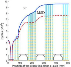
PoF results: The single flight hour PoF was calculated using ProDTA for the SC and MSD scenarios, using both master curve and Monte Carlo methods. The results are presented in Fig. 15. The comparison indicates that the PoF for the MSD scenario is significantly higher than the PoF for the SC scenario, especially in the end-of-life stage. Therefore the maintenance schedule should be revised for the MSD scenario, based on the MSD/MED risk analysis, the MSD/MED DTA, and the residual strength analysis. 1E-12 1E-11 1E-10 1E-09 1E-08 1E-07 1E-06 1E-05 1E-04 1E-03 1E-02 1E-01 1E+00
0.00E+00 4.00E+06 8.00E+06 1.20E+07
S ingle hour P o F , P o F (t) Cycles
ProDTA: SC (Monte Carlo, same EIFSD) ProDTA: SC (Master curve approach)
ProDTA: MSD (Monte Carlo, same EIFSD)
ProDTA: MSD (Master curve approach)
Fig. 16. Single flight hour PoF results for the SC and MSD scenarios
4.2 CC-130 CW-14B Location, With and Without MSD/MED
The typical CC-130 centre wing spar cap CW-14B is shown in . This location also showed MSD indication in service. Using the NRC DTA tools, the input data for the risk analysis were developed as follows.
Fig. 17. CC-130 centre wing lower surface panel fatigue critical location (CW-14B) • Initial crack size distribution (ICSD): Using the CF in-service crack data, the EIFS
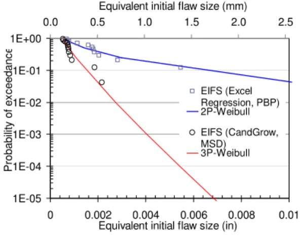
values were regressed using the NRC program CanGROW, and then a best-fit statistical distribution was determined. Fig. 17 presents the EIFS results for the SC and MSD scenarios, as a function of the probability of exceedance, using the 12 cracks found in service.
1E-05 1E-04 1E-03 1E-02 1E-01 1E+00 0 0.002 0.004 0.006 0.008 0.01 Equivalent initial flaw size (in)
P roba bil ity of ex c eed anc e 0.0 0.5 1.0 1.5 2.0 2.5
Equivalent initial flaw size (mm)
EIFS (Excel Regression, PBP) 2P-Weibull EIFS (CandGrow, MSD) 3P-Weibull
Fig. 18. EIFSD for CW-14B
• Crack growth curve and lead crack size distribution: Using the developed β-library embedded in CanGROW and the NRC generic beta tool, the total β-factor was determined for the CW-14B location for the SC and MSD scenarios, as shown in Fig. 19. The crack growth curves for the SC and MSD scenarios, presented in Fig. 20, were obtained by CanGROW, using the Mini-TWIST spectrum.
0 0.5 1 1.5 2 2.5 3 3.5 0 50 100 Lead Crack Size (mm) SC MSD
Fig. 19. β-solutions of the lead crack for the SC and MSD scenarios
Using the same random EIFSD, the tail sampling based Monte Carlo simulation, i.e, 105 trials from the 10% tail, was performed by CanGROW to determine the lead crack size distributions for the risk analysis.
Lower spar cap Lower wing panel Spar web Lead crack Up Aft
ADVANCED DAMAGE TOLERANCE AND RISK ASSESSMENT METHODOLOGY AND TOOL FOR AIRCRAFT STRUCTURES CONTAINING MSD/MED
0 0.5 1 1.5 2 2.5 3 3.5 0 50 100 150 Cr a ck Si ze (m m ) Cycles (x103) SC MSD
Fig. 20. Crack growth curves for the SC and MSD scenarios (lead crack only)
• Maximum stress distribution: The maximum stress distribution, presented in Fig. 20, was determined for the Mini-TWIST spectrum using the stress exceedance data per single flight hour.
0 50 100 150 1E-05 1E-04 1E-03 1E-02 1E-01 1E+00 0 5 10 15 20 25 Max. stress (Mpa)
P rob ab ili ty of exc e e d a n c e p er h ou r
Max. stress (ksi) Max. Stress Exceedance per hour
Gumbel Fit (Berens, 5pts) Gumbel Fit (Berens, 4pts)
Fig. 21. Maximum stress distribution
• Residual strength: Using the aforementioned methods, and the total β-factor for the CW-14B location (Fig. 19), the RS curve was calculated for the SC scenario, as presented in Fig. 22. This RS curve was also used for the MSD risk analysis, assuming that the RS difference between the two scenarios would be marginal.
PoF results: Using the above input data, the single flight hour PoF results were calculated by ProDTA and are presented in Fig. 23, for both the SC and MSD scenarios. The comparison indicates that the PoF for the MSD scenario is much higher than that of the SC crack scenario, especially at the end-of-life stage. It is also noted that the PoF for the MSD scenario increases dramatically after a certain lifetime point, which is assumed to be due to MSD crack link-up. Again, the maintenance schedule
should be reconsidered if MSD indications were revealed in service. 0 0.2 0.4 0.6 0.8 1 1.2 0 10 20 30 40 50 60 70 80 90 100 N o rm a liz e d σRS
Lead crack length (mm)
NSY
Local plastic zone link-up Link to continuing damage Kc ho le 2 ho le 1 ho le 3
Fig. 22. Residual strength curve (SC scenario)
1E‐15 1E‐13 1E‐11 1E‐09 1E‐07 1E‐05 1E‐03 1E‐01 0 20 40 60 80 100 120 140 160 180 200 Si n g le flig h t ho ur Po F Cycles (x103) ProDTA (SC, 2P‐ Wei EIFSD) ProDTA (MSD, Monte Carlo, 3P‐ Wei EIFSD)
Fig. 23. Single flight hour PoF results for the SC and MSD scenarios
5. Concluding Remarks
For quantitative risk assessment, especially for the MSD/MED scenario, extensive DTA is required to prepare quality input data, quantify the damage evaluation process, and then assist engineering judgments needed in a practical risk analysis. To support the CF RARM process on a regular basis and within a quick turn-around time, efficient methods and generic tools are needed for the DTA and risk analysis.
In this paper, the advanced DTA and risk analysis methods and tools, including the NRC β-factor library, FE based generic β-factor tool, crack growth program CanGROW, and enhanced risk analysis program ProDTA, were presented for built-up structures with and without MSD/MED. These methods and tools are also being expanded for generic aircraft structural damage tolerance analysis and risk
assessment. The presented case studies carried out on the CC-130 locations that are also typical configurations found in many aircraft structures, demonstrated the generic capability of the developed methods/tools. Recently, these methods/tools were also applied and demonstrated in support of another CF aircraft risk assessment. The case study results indicate that the PoF for the MSD scenario can become significantly higher than the SC crack scenario, especially at the end-of-life cycles, which suggesting both the DTA and risk analysis results are required to adjust the maintenance plan for the MSD/MED scenario.
Acknowledgements
This work was performed with financial support from the Department of National Defense of Canada (DND) and NRC. Thanks to T. Cheung, Y. Caron, J. Gaerke, and K. McRae of DND for providing some data and technical discussions.
References
[1] National Transportation Safety Board LAX02GA201, NTSB Identification: LAX02GA201, http://www.ntsb.gov/ntsb/brief2.asp?ev_id=2002062
1X00954&ntsbno=LAX02GA201&akey=1
[2] Liao M., Bombardier Y., Renaud G., Bellinger N.C. and Cheung T. Development of advanced risk assessment methodologies for aircraft structures containing MSD/MED, The 31st CONFERENCE and
the 25th SYMPOSIUM of the International Committee on Aeronautical Fatigue (ICAF),
Rotterdam, Netherlands, June 2009.
[3] Federal Aviation Administration – Regulations and
policies, task 6 – Widespread fatigue damage,
Aviation Rulemaking Advisory Committee, Transport Airplane and Engine Issue Area, http://www.faa.gov/regulations_policies/rulemaking/ committees/arac/media/tae/TAE_AA_T6.pdf
[4] Advisory Circular (DRAFT), Widespread fatigue
damage, AC 120-YY, Initiated by: ANM-100 and
AFS–300, Federal Aviation Administration, Flight Standards Service, Washington, D.C.
[5] Bombardier Y., Liao M., and Renaud G. Fracture mechanics modeling of multiple site damage scenarios, The 12th International Congress of
Fracture, Ottawa, Canada, 2009.
[6] Bombardier Y. and Liao M. A new stress intensity factor solution for cracks at an offset loaded fastener hole, The 51st AIAA/ASME/ASCE/AHS/ ASC
Structures, Structural Dynamics, and Materials Conference, 2010.
[7] Bombardier Y. and Liao M. Evaluation of stress
intensity factor solutions for radially and diametrically corner cracked holes, National
Research Council Canada, LTR-SMPL-2009-0112. [8] Poe Jr. C.C. Stress- intensity factor for a cracked
sheet with riveted and uniformly spaced stringers,
NASA Tech Rep R-358, 1971.
[9] Miedlar, P. C., Berens, A. P., Gunderson, A., and Gallagher, J. P., "USAF Damage Tolerant Design Handbook: Guidelines for the Analysis and Design of Damage Tolerant Aircraft Structures," AFRL-VA-WP-TR-2003-3002, 2002.
[10] Renaud G., Liao M., and Bombardier Y. Development of stress intensity correction factors for built-up structures with multiple element damage,
The 2010 Aircraft Airworthiness and Sustainment Conference, Austin, USA, May 2010.
[11] Swift T. Widespread fatigue damage monitoring– issues and concerns, Proceedings of the 5th
International Conference on Structural Airworthiness of New and Aging Aircraft, June 16-18, Hamburg,
Germany, 1993.
[12] Department of National Defense of Canada review of
open records of airworthiness risk management,
Department of National Defense of Canada, Airworthiness Directive (AD) DND-AD-2007-01. [13] Liao M., Bellinger N.C., Forsyth D.S., and
Komorowski J.P. A new probabilistic damage tolerance analysis tool and its application for corrosion risk assessment, Proceedings of the 23rd
ICAF Symposium, Hamburg, Berlin, EMAS
Publishing, pp 241-252, 2005.
[14] Liao M., Renaud G., Bombardier Y., Bellinger N.C. Development of initial crack size distribution for risk assessment of aircraft structures, Proceedings of the
RTO-MP-AVT-157 Military Platform Ensured Availability Symposium, Montreal, Canada, 2008.
Contact Author Email Address
Copyright Statement
The authors confirm that they, and/or their company or organization, hold copyright on all of the original material included in this paper. The authors also confirm that they have obtained permission, from the copyright holder of any third party material included in this paper, to publish it as part of their paper. The authors confirm that they give permission, or have obtained permission from the copyright holder of this paper, for the publication and distribution of this paper as part of the ICAS2010 proceedings or as individual off-prints from the proceedings.