HAL Id: hal-01151808
https://hal.archives-ouvertes.fr/hal-01151808
Submitted on 13 May 2015
HAL is a multi-disciplinary open access
archive for the deposit and dissemination of
sci-entific research documents, whether they are
pub-lished or not. The documents may come from
teaching and research institutions in France or
abroad, or from public or private research centers.
L’archive ouverte pluridisciplinaire HAL, est
destinée au dépôt et à la diffusion de documents
scientifiques de niveau recherche, publiés ou non,
émanant des établissements d’enseignement et de
recherche français ou étrangers, des laboratoires
publics ou privés.
Antennas with Circular-Polarization in the 60-GHz
Band
Hamza Kaouach, Laurent Dussopt, Ronan Sauleau
To cite this version:
Hamza Kaouach, Laurent Dussopt, Ronan Sauleau. Modeling, Design and Demonstration for Discrete
Lens Antennas with Circular-Polarization in the 60-GHz Band. International Journal of Research in
Wireless Systems (IJRWS), 2012, pp.9. �hal-01151808�
Modeling, Design and Demonstration for Discrete
Lens Antennas with Circular-Polarization
in the 60-GHz Band
Hamza KAOUACH
1, Laurent DUSSOPT
2, Ronan SAULEAU
31 College of Engineering at Al-Lith, ECED, Umm Al-Qura University, Saudi Arabia 2 CEA-LETI, MINATEC Campus, 17 rue des martyrs, 38054 Grenoble, France
3 IETR, UMR CNRS 6164, University of Rennes I, 35042 Rennes, France hmkaouach@uqu.edu.sa – hamza.kaouach@gmail.com Abstract—This paper presents the modeling, design and
demonstration of two circularly-polarized Transmit-Arrays (TA) operating in the 60-GHz band and generating a broadside beam and a 30°-tilted beam respectively. These arrays have a fairly simple structure with only three metal layers and are fabricated with a standard printed-circuit board technology. The simulated results show the performances of the unit-cells as well as the whole arrays, and detail their power budget. The experimental results in V-band are in very good agreement with the simulations and demonstrate very satisfactory characteristics. Power efficiencies up to 53.7% are reached with a 1-dB gain-bandwidth up to 9.1%, and low cross-polarization level.
Key Words—Discrete lens, transmit-array, unit-cell, 60-GHz band, millimeter-wave antennas.
I.
I
NTRODUCTIONTechnology advances in low-cost millimeter-wave integrated circuits have triggered a lot of application perspectives for wireless communication systems in V- and E-bands [1]–[3]. In particular, wide license-free frequency bands are available worldwide in the 57–66 GHz range, and several standardization groups are working on regulatory rules for wireless high-definition video transmission [4], [5], wireless personal and local area networks [6]–[8], and radio-over-fiber networking solutions [9]. The main common requirements for these applications are the following: low-cost, high efficiency antenna solutions, and ease of integration in user terminals or base stations (cell phone, laptop, set-top box, etc.).
Discrete lenses (also called transmit-arrays) [12] are high-directivity planar multilayer antennas currently investigated for many applications in the microwave and millimeter-wave bands, such as point-to-point communications, satellite communications, or civil and military radars. Compared to other antenna solutions (horn antennas, dielectric lenses, reflectors, and reflect-arrays), promising characteristics have been already demonstrated at frequencies below X-band in terms of efficiency,
lie in the V-band (57-66 GHz) such as wireless high-definition video transmission, personal or local area networks, radio-over-fiber networking solutions, or in the E-band (70-80 GHz) for metropolitan area networks [2] [16].
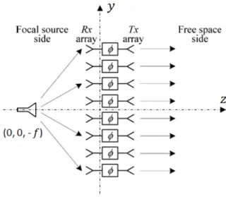
Fig. 1. Operation principle of a transmit-array in transmit mode. The transmit-array consists of two Rx and Tx antenna arrays connected by phase shifters. The latter are used to modify the signal phase delay and thus to control the main beam direction of the transmit-array.
To our best knowledge, the work presented here is the first one investigating the radiation performance of circularly-polarized (CP) transmit-arrays operating in V-band [17]. The corresponding unit-cell relies on similar concepts as those recently introduced in X-band to generate either linear or circular polarization with a very simple fabrication process and low insertion loss [18] [19].
The paper is organized as follows. The geometry and characteristics of the proposed unit-cells are presented in Sections II.A II.B. The analysis, design and expected performance of circularly-polarized transmit-arrays are
Fig. 2. Perspective view of the transmit-array antenna (a), top view (b) and bottom view (c) photographs of the broadside-beam transmit-array.
II.
A
NTENNAD
ESIGN ANDN
UMERICALR
ESULTSA. Description of the unit-cell
The proposed unit-cell is represented in Fig. 3. Its size is 2.5×2.5 mm2 (λ
0/2×λ0/2 at 60 GHz), and it consists of two identical square patch antennas (1.55×1.55 mm2) connected by a vertical via. The bottom patches (focal source side) have the same orientation for every cells, while the top patches (free space side) are rotated by an angle α (α = 0°, 90°, 180°, and 270°) for the four different unit-cells, generating a circularly-polarized (CP) wave through sequential rotation (Fig. 3b).
The geometry and performances of these unit-cells were described in detail in [17]. They were designed using the Ansys-HFSS electromagnetic simulation software using Floquet ports and periodic boundary conditions. Their simulated S-parameters under normal incidence show a reflection coefficient lower than -10 dB at 59.5-61.9 GHz, an insertion loss of 0.35 dB at 60.4 GHz, and a 1-dB transmission bandwidth of 3.9 GHz (6.5%). Their theoretical radiation patterns at 60 GHz show a maximum gain of 4.85 dBi and a 3-dB beamwidth of 88° and 131° in E- and H-planes, respectively.
Figure 4 shows the variation of the S-parameters of the 0° unit-cell for several incidence angles from 0° to 45° in the E-plane. The resonant frequency of the patches is slightly decreasing for increasing incidence angles. For a 45° incidence, the central frequency is shifted to 59.3 GHz, the insertion loss is slightly increased to 0.44 dB, and the 1-dB bandwidth is reduced to 2.45 GHz (4.1%). Above 67 GHz, a higher-order resonance mode appears for a 45° incidence, but this mode does not have any visible effect on the full transmit-array. In H-plane, a similar but weaker effect is observed with a frequency shifted to 59.6 GHz for 45° incidence. Similar results are obtained for the three other unit-cells as well.
Fig. 3. Geometry of the unit-cell. (a) Cross-section view of the 0° unit-cell. (b) Top view of the four unit-cells; the bottom patches in dotted lines are horizontally polarized, the top patches in continuous lines are rotated by 90° between each cell.
Fig. 4. Computed reflection and transmission coefficients of the 0° unit-cell under several incidence angles (0°, 15°, 30°, 45°) in E-plane. F D Transmit-array Dielectric struts Horn Metal plate (a) (b) (c) (a) α = 0° E α = 90° E α = 180° E α = 270° E (b) Focal source side
Free space side patch patch RO3003 Duroid 6002 4403 50 55 60 65 70 Frequency (GHz) -30 -25 -20 -15 -10 -5 0 Refle ction, transmission (dB) 0° incidence 15° incidence 30° incidence 45° incidence Reflection Transmission
As explained in the next section, the F/D ratio of transmit-arrays designed here equals 0.5, which means that the highest incidence angle reached for the unit-cells located at the center of the array edges will be 45°.
Figure 4 confirms that good performances are preserved. Although their contribution are of minor importance, the unit-cells located in the four corners of the array will see a highest incidence angle of 54.7° in their diagonal plane, but simulations have shown that the S-parameters deviations were negligible as well.
B. Lumped-element electrical model
The equivalent lumped-element electrical model of the unit cell consists of two resonators connected by an LC circuit (Fig. 5). Each resonator represents the TM10 resonant mode of the patches [20] and the LC T-network models the via hole connection. Both patches are coupled to the input/output ports (377 Ω wave impedance) through ideal transformers.
Fig. 5: Equivalent electrical model of the unit-cell.
All components of this model are calculated using analytical expressions taking into account the physical parameters of the structure. The equivalent lumped-element electrical model of the rectangular patches fed by metalized via has been developed using the cavity model [20]. It can be represented as shown in Fig. 5, where Rp, Cp, and Lp are the equivalent resistance, capacitance, and inductance of the patch [20].
𝐶𝑝=𝜀𝑒𝑓𝜀2ℎ0𝐿𝑊𝑐𝑜𝑠−2�𝜋𝑦𝐿 �0 1 𝐶𝑝=𝐶 1 𝑝. 𝜔𝑟2 2 𝑅𝑝=𝐶𝑄𝑟 𝑝. 𝜔𝑟 3 In these equations, L and W denote the length and the width of the patch respectively; h is the thickness of the substrate, Ԑef is the effective dielectric constant [20], Ԑ0 is
the permittivity of free-space, and y0 is the feed point position. ωr and Q are the angular frequency at resonance
and the radiation quality factor of the patch respectively [20].
The metalized via hole is modeled by a series inductance (Lvia) [21] and a shunt capacitance (C) [22].
𝐿𝑣𝑖𝑎=𝜇2𝜋 𝑙𝑛 �0ℎ 𝜋𝛾𝑑√𝜀2𝑐 𝑟𝑓� 4 𝐶 = 𝜀0𝜀𝑟2𝜋 ℎ𝑔𝑟𝑜𝑢𝑛𝑑 𝑙𝑛 � 𝑟1 𝑟𝑣𝑖𝑎� 5
where c is the speed of the light in the free-space, γ
is the Euler’s constant, Ԑr is the relative dielectric constant
of the substrate, d is the diameter of the metalized via, μ0 is the magnetic permeability of free-space, hground is the
thickness of the ground plane, rvia is the radius of the
metalized via, and r1 is the radius of the hole in the ground plane. A very good agreement is obtained between both approaches [23].
C. Analysis of Transmit-Arrays
In the TA the transformation between the spherical and planar wave-fronts is achieved through the phase delay of the comprising cells (Fig. 1). The input-output phase delay for each cell is a function of frequency, and can be written in terms of the S-parameters of the corresponding TA element (unit-cell).
𝛷𝑚
(
𝜔)
= −∠𝑆21𝑚(
𝜔)
6Where m is the unit-cell index. To achieved the desired wave transformation at a given frequency ω0, the TA modules must be designed to provide the necessary phase delay at that frequency.
The required value of phase delay at the centre of the mth is given by
𝛷𝑚=2𝜋𝜆
0�𝑓 − �𝑥𝑚
2 + 𝑦𝑚2 + 𝑓2� − 𝛷
0(𝑥𝑚, 𝑦𝑚) 7
Where 𝜆0 is the free-space wavelength at the design frequency, 𝑓 is the focal length, 𝑥𝑚 and 𝑦𝑚 are the co-ordinates of the mth unit-cell in the TA co-ordinate systems, and 𝛷0(𝑥𝑚, 𝑦𝑚) is a known phase function associated with the output wavefront.
A simple analysis of the TR can be performed based on elementary antenna and array concepts. The analysis method assumes that the frequency responses of the TA unit-cells depend on the angle of incidence only through the directivity of the patch antennas. This is believed to be a reasonable assumption for transmit-arrays with modest
values of subtended angle (𝑓/𝐷 ≤ 1). Although it may not be apparent, mutual coupling is accounted for (in an approximate fashion) by using the S-parameters of the TA unit-cells in a periodic array.
Assuming that the TA is illuminated by a feed antenna located at its focal point (0, 0, - 𝑓) with the directional gain of 𝐺𝑓(𝜃, 𝜑) and unit input power, the power received by the mth element in the array can be calculated from Friis’ formula
𝑃𝑟𝑒𝑐𝑚 = �4𝜋𝑟𝜆𝑚� 2
𝐺𝑓(𝜃𝑚, 𝜑𝑚)𝐷𝑒(𝜃𝑚, 𝜑𝑚) 8 Where 𝜆 is the wavelength at the operation frequency in general different than the design frequency, De is the directivity of the patch antennas in the TA elements, and (𝑟𝑚, 𝜃𝑚, 𝜑𝑚) are the spherical co-ordinates of the mth element in the co-ordinate system
𝑟𝑚= �𝑥𝑚2 + 𝑦𝑚2 + 𝑓2 9 𝜃𝑚= 𝑡𝑎𝑛−1�𝑥𝑚 2 + 𝑦𝑚2 𝑓 10 𝜑𝑚=|𝑦𝑦𝑚 𝑚| 𝑐𝑜𝑠 −1 𝑥𝑚 �𝑥𝑚2 + 𝑦𝑚2 11
Adopting the two-port scattering parameters nota-tion, the amplitude of the incident wave at the input port (port 1) of the mth unit-cell, can be written as
𝑎1𝑚= �𝑃𝑟𝑒𝑐𝑚𝑒−𝑗2𝜋/𝜆𝑟𝑚 12 Where a phase factor has been introduced to account for the propagation delay between the focal source and TA receive antennas. This equation is based on the assumption of using a focal feed source with well-defined phase centre. For actual horn or open-ended waveguide feeds the spherical phase relationship is approximate and is valid only for modest values of subtended angle. The outgoing wave at the output port (port 2) of the mth unit-cell is given by
𝑏2𝑚= 𝑆21𝑚(𝜔)𝑎1𝑚 13
Combining the last equations, we obtain
𝑏2𝑚=4𝜋𝑟𝜆𝑚�𝐺𝑓(𝜃𝑚, 𝜑𝑚)𝐷𝑒(𝜃𝑚, 𝜑𝑚)𝑒−𝑗2𝜋/𝜆𝑟𝑚𝑆21𝑚(𝜔) 14 The values of {𝑏2𝑚} are proportional to the (complex) amplitudes of the patch currents on the transmit side sometimes referred to as the nonfeed side [24] of the TA, and can be considered as the output array coefficients. The radiated power density at a far-field observation point (𝑟, 𝜃, 𝜑) is calculated from 𝑆(𝜃, 𝜑) =𝐷𝑒4𝜋𝑟(𝜃, 𝜑)2 �� 𝑏2𝑚𝑒𝑗2𝜋/𝜆�𝑥𝑚 2+𝑦 𝑚2𝑠𝑖𝑛𝜃cos (𝜑−𝜑𝑚� 2 15 Where the summation is over all the TA elements. If the interaction between the radiating elements is negligible the total radiated power is given by
𝑃𝑜𝑢𝑡= �|𝑏2𝑚|2 16
The directivity of the TA can be calculated as the ratio of the radiated power density to what would have been obtained from the isotropic radiation of the output power
𝐷(𝜃, 𝜑) =𝑃 1 𝑜𝑢𝑡⁄4𝜋𝑟2𝑆(𝜃, 𝜑) = 𝐷𝑒(𝜃, 𝜑) �∑ 𝑏2𝑚𝑒𝑗2𝜋/𝜆�𝑥𝑚 2+𝑦 𝑚2𝑠𝑖𝑛𝜃cos (𝜑−𝜑𝑚� 2 ∑|𝑏2𝑚|2 17 Considering that the total power received is given by
𝑃𝑟𝑒𝑐= �|𝑎2𝑚|2 18
The power transfer efficiency (ηt) can be defined as
ηt=𝑃𝑃𝑜𝑢𝑡 𝑟𝑒𝑐 =
∑|𝑏2𝑚|2 ∑|𝑎2𝑚|2
19
The internal losses of the TA elements are therefore included in ηt. Besides these and the loss of the feed
antenna (included in G𝑓), the only additional source of loss is the spill-over, i.e., power radiated by the focal source outside the angular sector covered by the transmit-array. This loss can be included by introducing a spill-over efficiency factor
ηSO=𝑃𝑃𝑟𝑒𝑐
𝑖𝑛= 1 = �|𝑎2
𝑚|2 20
The power efficiency (η) of the TA antenna is defined as the ratio of the total radiated power on the free-space side to the focal source input power (Pin)
η =𝑃1 𝑖𝑛�|𝑏2
𝑚|2 21
The gain of the TA is defined similar to its directivity, except for being measured against the input power (equal to unity in this case) instead of the Prec.
𝐺(𝜃, 𝜑) =(𝑃 1 𝑖𝑛 = 1) 4𝜋𝑟⁄ 2𝑆(𝜃, 𝜑) = 𝐷𝑒(𝜃, 𝜑) �� 𝑏2𝑚𝑒𝑗2𝜋/𝜆�𝑥𝑚 2+𝑦 𝑚2𝑠𝑖𝑛𝜃cos (𝜑−𝜑𝑚� 2 22 This gain is related TA directivity through ηt and ηso
𝐺(𝜃, 𝜑) = η𝑡η𝑠𝑜𝐷(𝜃, 𝜑) 23
D. Antenna Configuration and Design of Transmit-Arrays The focal source is a 10-dBi linearly-polarized pyramidal horn. A fixture composed of a metal plate and four dielectric struts (Delrin, Ø = 6 mm) is used to hold and align the array and the focal source. The size of the transmit-array was chosen as 20×20 unit-cells (50×50 mm2, 10λ0×10λ0 at 60 GHz), which corresponds to a maximum theoretical directivity of 31 dBi for a uniform aperture distribution.
The design and simulation procedure of such antennas is similar to those applied for reflect-arrays. This has been described in previous papers [18]. Several circularly-polarized transmit-arrays have been designed and fabricated based on the four unit-cells presented in
Section II.A. Figure 6a shows the directivity, gain, and axial ratio that can be achieved as a function of the ratio F/D for a broadside beam and a 30° beam-shift. F/D is defined as the ratio of the distance F between the array and the focal source to the side dimension D of the array (as mentioned above, D = 50 mm or 10λ0 at 60 GHz).
The directivity increases as a function of the focal distance and converges toward a maximum value for large focal distances corresponding to a uniform aperture illumination of the array. The maximum directivity for the broadside beam is 27 dBi, because of a 4-dB quantification loss due to the 90° phase resolution. The gain is maximum for F/D = 0.5, this value corresponds to the best trade-off between the taper loss for low F/D values, and the spill-over loss for high F/D values. The axial ratio oscillates between 0.6 and 2.3 dB as a function of F/D, as a result of the array finite unit-cell number and phase quantification. For a 30° beam-shift, the directivity and gain are reduced by about 1.6 dB as a result of the finite beamwidth of the unit-cells. The axial ratio in this case is nearly independent of F/D (~1.1-1.4 dB).
Based on this study, two transmit-arrays were designed with F/D = 0.5 (F = 25 mm) and with a broadside beam or 30°-tilted beam. The unit-cell distributions of these two designs are represented in Fig. 6b. Their power budget is detailed in Table I. In both cases, the taper loss, spill-over-loss and insertion loss equal 0.9 dB, 2.24 dB, and 0.46 dB respectively. The quantization loss equals 4.7 dB for the broadside-beam design, and 5.4 dB for the 30° beam-shifted design. The radiation efficiency, defined as the ratio of the gain to the directivity is 53.6-53.7%. The experimental gain values are in good agreement with the theory, confirming thereby this power budget analysis. It is important to note that quantization losses can theoretically be reduced down to zero using circularly-polarized elements on the free-space side and appropriate rotation angle α for each cell, which would significantly improve the gain and directivity of the antenna.
III.
E
XPERIMENTALR
ESULTSFigure 7 shows the reflection coefficient measured at the input port of the feed horn with (F = 25 mm) and without the discrete lens. In both cases, a very good matching is preserved across the V-band (50-75 GHz).
The two prototypes have been characterized between 50 and 70 GHz in the main beam direction (Fig. 9). For the broadside-beam prototype (Fig. 8a), a good agreement with the simulation is obtained across the whole measurement frequency band. The gain-frequency response shows a band-pass characteristic with a simulated 1-dB bandwidth of 57.5-68.5 GHz. The experimental 1-dB bandwidth starts at 58.3 GHz but its
higher cut-off frequency was rejected beyond 70 GHz and could not be measured. The axial ratio response is also in good accordance with the simulations with an axial ratio lower than 3 dB across the whole measurement band and lower than 1 dB from 57 to 66 GHz. This good polarization quality is obtained across the whole bandwidth of the array thanks to the sequential rotation configuration.
Fig. 6. Theoretical directivity, gain and axial ratio of the transmit-arrays as a function of F/D (a); unit-cell distribution of the proposed transmit-arrays with a broadside beam (b) and 30°-shifted beam (c).
For the tilted-beam prototype (Fig. 8b), the gain-frequency response in the main beam direction shows a good agreement with the simulation for the lower half of the frequency band, but the band-pass shape is not well defined in the upper half. The measured 1-dB bandwidth equals 58.5-64.1 GHz (5.6 GHz, 9.1%), and is significantly larger than the simulated one (57.3-61.4 GHz, 6.9%). A possible cause for this discrepancy is the fabrication dispersions across the array, which may be more critical in a tilted-beam case. The most challenging dimensions are the via diameter (∅ = 0.1 mm) and the ground plane aperture diameter (∅ = 0.3 mm) around each via, which are critically small for this fabrication technology. The experimental axial ratio response at θ = 30° exhibits strong similarities with the simulations with a minimum close to 0.5 dB and a steep increase for frequencies above 65 GHz,
the measured 3-dB axial ratio bandwidth is 57.8-63.1 GHz (5.3 GHz, 8.8%). This small bandwidth (compared to the broadside-beam transmit-array) observed when measuring at θ = 30° is due to the variation of the main beam direction as a function of frequency. Hence, the simulated main beam direction varies from 36.5° down to 25° across the 50-70 GHz band (Fig. 9). On the other hand, the simulated axial ratio in the main beam remains below 2 dB across the whole band (Fig. 8b).
TABLE I.POWER BUDGET AND GAIN OF THE TWO PROTOTYPES AT 60GHZ (F/D=0.5).
Beam angle 0° 30°
Max. theoretical directivity (dBi) 31 30.4
Quantization loss (dB) 4.6 5.4
Taper Loss (dB) 0.9 0.9
Antenna directivity Dant (dBi) 25.5 24.1
Spill-over loss (dB) 2.24 2.24
Insertion loss (dB) 0.46 0.46
Theoretical gain (dBi) 22.8 21.4
Radiation efficiency (%) 53.6 53.7
Axial ratio (dB) 0.76 0.88
Measured gain (dBi) 23 21.9
The simulated and measured radiation patterns of the broadside-beam arrays are plotted in Fig. 10. This Figure confirms the very good agreement between simulations and experiments: the computed and measured gain, beamwidth and side lobes equal 22.8/23 dBi (sim./meas.), 6.1°×6.6°/6.6°×7.2° (sim./meas.), and -19.6/-16.1 dB (sim./meas.), respectively. The cross-polarization level in the main beam is lower than -25 dB in simulation and close to -20 dB experimentally.
Fig. 7. Measured reflection coefficient at the input of the horn focal source alone and with a discrete lens at a distance F = 25 mm (F/D = 0.5).
The tilted-beam prototype exhibits experimentally a main beam at θ = 26.5±1°, slightly shifted from the design value (30°). This shift is attributed to (i) the relative
(b) (c)
(a)
Cell #1 Cell #2 Cell #3 Cell #4
0 0.25 0.5 0.75 1 1.25 1.5 F/D ratio 0 5 10 15 20 25 30 Gain, Directivity ( dBi) 0 2 4 6 8 10 12 Axial Rati o (dB) Beam dir. : 0° 30° Directivity : Gain : Axial Ratio : 50 55 65 75 Frequency (GHz) 60 70 -20 -10 0 Reflectio n Coeffici ent(dB) -40 -30 F = 25 mm Horn
position of the focal source and the array, and (ii) a slightly bowed shape of the array which is thin and flexible. The simulated and measured radiation patterns are again in good agreement (Fig. 11).
Fig. 8. Computed and measured gain and axial ratio for the broadside (a) and beam-shifted (b) transmit-arrays.
Fig. 9. Computed and measured beam direction of beam-shifted transmit-arrays as a function of frequency.
Fig. 10. Computed (a) and measured (b) radiation patterns of the broadside-beam transmit-array at 60 GHz in the vertical plane.
IV.
C
ONCLUSIONLow-cost directive antennas are strongly needed for emerging wireless applications in the millimeter-wave domain. In this article, V-band circularly-polarized discrete-lenses based on a simple three-metal layer unit-cell are studied. Their numerical characterizations lead to very promising features: low insertion loss, good efficiency, broad radiation pattern, and broadband phase response with a 2-bit quantization in circular polarization.
Two discrete lenses have been studied numerically and experimentally, designed and fabricated for a broadside beam or a beam tilted at 30°. Its measured radiation characteristics are in very good agreement with the simulations in terms of gain frequency response, axial ratio, and radiation pattern.
(a) 0 5 10 15 20 25 Gain (dBi) 50 55 60 65 70 Frequency (GHz) 0 2 4 6 8 10 Axial Rat io (dB) (b) 50 55 60 65 70 Frequency (GHz) 0 5 10 15 20 25 Gain (dBi) 0 2 4 6 8 10 Axial Ratio (dB) AR at θ = 30° AR in the main beam 50 55 60 65 70 Frequency (GHz) 20 25 30 35 40
Beam direction (deg.)
Sim. Meas. (a) (b) -20 -15 -10 -5 0 5 10 15 20 25 Gain (dBi) -90 -60 -30 0 30 60 90 Angle (deg.) -20 -15 -10 -5 0 5 10 15 20 25 Gain (dBi) -90 -60 -30 0 30 60 90 Angle (deg.) LHCP RHCP
Fig. 11. Computed (a) and measured (b) radiation patterns of the 30°-beam-shifted transmit-array at 60 GHz.
A
CKNOWLEDGEMENTSThe authors would like to thank the European Science Foundation for its contribution to the work (project RNP NEWFOCUS). They also would like to thank CEA and CNES for their financial support.
R
EFERENCES[1] A. M. Niknejad, “Siliconization of 60 GHz,” IEEE Microw.
Mag., vol. 11, no. 1, pp. 78–85, Feb. 2010
[2] S. Q. Xiao, M. T. Zhou, and Y. Zhang, Millimeter Wave
Technology in Wireless PAN, LAN, and MAN, CRC Press,
2008.
[3] P. Smulders, “Exploiting the 60 GHz band for local wireless multimedia access: Prospects and future directions,” IEEE
Commun. Mag., Jan. 2002.
[4] WirelessHD [Online]. Available: http://www.wirelesshd.org. [5] Standard ECMA-387 (2008, Dec.). High Rate 60 GHz PHY,
MAC and HDMI PAL [Online]. Available: http://www.ecma-international.org/publications/standards/Ecma-387.htm [6] Millimeter Wave Alternative PHY [Online]. Available:
http://www.ieee802.org/15/pub/TG3c.html IEEE 802.11 Working Group, Wireless PAN Task Group 3c (2009). [7] [Online]. Available: http://www.ieee802.org/11/Reports/
tgad_update.htm IEEE 802.11 Working Group. Very high throughput in 60 GHz.
[8] Wireless Gigabit Alliance [Online]. Available: http://wireless-gigabitalliance.org.
[9] T. Chen, H. Woesner, Y. Ye, and I. Chlamtac, “WiGEE: A hybrid optical/wireless Gigabit WLAN,” in Proc. IEEE Global
Telecommunications Conf. (Globecom’07), Washington, DC,
Nov. 26–30, pp. 321–326, 2007.
[10] L. SCHWARTZMAN, L. TOPPER, “Analysis of phased array lenses,” IEEE Transactions on Antennas and Propagation, vol. 16, no. 6, p. 628 – 632, 1968.
[11] D. T. MCGRATH, “Planar three-dimensional constrained lenses,” IEEE Transactions on Antennas and Propagation, vol. 34, no. 6, p. 46 – 50, 1986.
[12] D. M. POZAR, “Flat lens antenna concept using aperture coupled microstrip patches,” Electronics Letters, vol. 32, no. 23, p. 2109 – 2111, 1996.
[13] P. PADILLA DE LA TORRE, M. SIERRA-CASTANER, and M. SIERRA-PEREZ, “Design of a double array lens,” In
Proceedings of the 1st European Conference on Antennas
and Propagation, Nice, France, 2006.
[14] A. ABBASPOUR-TAMIJANI, K. SARABANDI, and G. M. REBEIZ, “A millimeter-wave bandpass filter-lens array,” IET
Microwaves, Antennas and Propagation, vol. 1, no. 2, p. 388
– 395, 2007.
[15] C.G.M. RYAN, M.R. CHAHAMIR, J. SHAKER, J. R. BRAY, Y.M.M. ANTAR, and A. ITTIPIBOON, “A wideband transmit array using dual-resonant double square rings,” IEEE
Transactions on Antennas and Propagation, vol. 58, no. 5, p.
1486 – 1493, 2005,
[16] FCC, “Millimeter wave 70-80-90 GHz service”, [Online]. Available at: http://wireless.fcc.gov/services/ index.htm? job=service_home.
[17] H. KAOUACH, L. DUSSOPT, J. LANTERI, T. KOLECK, and R. SAULEAU, “Circularly-polarized discrete lens antennas in the 60-GHz band,” In Proceedings of the 20th International
Conference on Applied Electromagnetics and Commu-nications, Dubrovnik, Croatia, 20-23 Sept. 2010.
[18] H. KAOUACH, L. DUSSOPT, R. SAULEAU, and T. KOLECK, “Design and demonstration of 1-bit and 2-bit transmit-arrays at X-band frequencies,” In Proceedings of the 39th
European Microwave Conference, Roma, Italy, 2009.
[19] H. KAOUACH, L. DUSSOPT, R. SAULEAU, and T. KOLECK, “X-band transmit-arrays with linear and circular polarization,”
In Proceedings of the 4th European Conference on Antennas and Propagation, Barcelona (Spain), 2010.
[20] R. GARG, P. BHARTIA, I. BAHL, and A. ITTIPIBOON, “Microstrip Antenna Design Handbook,” Artech House, Boston, MA, 2001.
[21] E. LIER, “Improved formulas for inut impedance of coax-fed microstrip patch antennas,” Microwaves, Optics and
Antennas, IEE Proceedings H, pp. 161-164, Aug. 1982.
[22] B. C. WADELL, “Transmission line design handbook,” Artech House, Boston, MA, 1991.
[23] A. CLEMENTE, L. DUSSOPT, R. SAULEAU, P. POTIER, and P. POULIGUEN, “Design and characterization of 2-bit passive
unit-cells and transmit-arrays in X-band,” 5th European
Conference on Antennas and Propagation, Eucap 2011,
Rome, Italy, 2011.
[24] D. POPOVIC, Z. POPOVIC, “Multibeam antennas with polarization and angle diversity,” IEEE Trans. Antennas
Propag., 50, pp. 651–657, 2002. (a) (b) 0 5 10 15 20 25 Gain (dBi) -20 -15 -10 -5 LHCP RHCP -90 -60 0 60 90 Angle (deg.) -30 30 LHCP RHCP -90 -60 0 60 90 Angle (deg.) -30 30 0 5 10 15 20 25 Gain (dBi) -20 -15 -10 -5
A
BOUTA
UTHORSHamza KAOUACH received the M.S. degree in high frequency communications systems from the University of Paris-Est Marne-la-Vallée, France, in 2006 and the Ph.D. degree in signal processing and telecommunications from the University of Rennes 1, France, in 2009. From 2006 to 2009, he was a Research Engineer at CEA-LETI, Grenoble, France. From 2010 to 2012, he was an Antenna and RF Engineer in industry at MATIS Group and PSA Peugeot Citroën Group, Paris, France. Since July 2012, he is an Assistant Professor at the Umm Al-Qura University, College of Engineering at Al-Lith (CEL), ECE Department, Makkah, Saudi Arabia. His research interests include quasi-optic reconfigurable antennas, antenna arrays and transmitarrays at millimetre-wave frequencies.
Laurent DUSSOPT received the M.S. and Agrégation degrees in electrical engineering from the Ecole Normale Supérieure de Cachan, France, in 1994 and 1995, the Ph.D. degree in electrical engineering from the University of Nice-Sophia Antipolis, France, in 2000, and the “Habilitation à Diriger des Recherches” degree from the University Joseph Fourier, Grenoble, France, in 2008. From September 2000 to October 2002, he was a Research Fellow with The University of Michigan at Ann Arbor. Since 2003, he is a Research Engineer at CEA-LETI, Grenoble, France. His research interests include reconfigurable antennas, millimeter-wave integrated antennas and antenna arrays, RF-MEMS devices and systems. Dr. Dussopt received the Lavoisier Postdoctoral Fellowship from the French government in 2000 and was a co-recipient of the 2002 Best Student Paper Award (Second Prize) presented at the IEEE Radio Frequency Integrated Circuit (RFIC) Conference.
Ronan SAULEAU graduated in electrical engineering and radio communications from the Institut National des Sciences Appliquées, Rennes, France, in 1995 (summa cum laude). He received the Agrégation degree from the Ecole Normale Supérieure de Cachan, France, in 1996, and the Doctoral degree in signal processing and telecommunications (summa cum laude) and the “Habilitation à Diriger des Recherche” degree (summa cum laude) from the University of Rennes 1, France, in 1999 and 2005, respectively. He was an Assistant Professor and Associate Professor at the University of Rennes 1, between September 2000 and November 2005, and between December 2005 and October 2009. He has been a full Professor in the same University since November 2009. His current research fields are numerical modelling (mainly FDTD), millimeter-wave printed and reconfigurable (MEMS) antennas, lens-based focusing devices, periodic and non-periodic structures (electromagnetic bandgap materials, metamaterials, reflectarrays, and transmitarrays) and biological effects of millimeter waves. He has received six patents and is the author or coauthor of more than 100 journal papers and 240 publications in international conferences. Prof. Sauleau received the 2004 ISAP Conference Young Researcher Scientist Fellowship (Japan) and the first Young Researcher Prize in Brittany, France, in 2001 for his research work on gain-enhanced Fabry-Perot antennas. In September 2007, he was elevated to Junior member of the “Institut Universitaire de France”. He was awarded the Bronze medal by CNRS in 2008.