Characterization and Model of Piezoelectrochemical
Energy Harvesting Using Lithium ion Batteries
The MIT Faculty has made this article openly available. Please share how this access benefits you. Your story matters.Citation Schiffer, Z. J., and C. B. Arnold. “Characterization and Model of Piezoelectrochemical Energy Harvesting Using Lithium Ion Batteries.” Experimental Mechanics, vol. 58, no. 4, Apr. 2018, pp. 605–11.
As Published http://dx.doi.org/10.1007/s11340-017-0291-1
Publisher Springer US
Version Author's final manuscript
Citable link http://hdl.handle.net/1721.1/116268
Terms of Use Article is made available in accordance with the publisher's policy and may be subject to US copyright law. Please refer to the publisher's site for terms of use.
Characterization and model of piezoelectrochemical energy harvesting using
lithium ion batteries
Z. J. Schiffer1, C. B. Arnold1
1
Princeton University Mechanical and Aerospace Engineering Department, PRISM
Corresponding author: Craig B. Arnold. cbarnold@princeton.edu. Phone: 609-258-0250.
Abstract: Although lithium ion battery research often focuses on electrochemical properties,
lithium ion intercalation materials are also mechanically active. Essentially, these materials exhibit a mechanical-electrochemical coupling such that when a stress is applied, the voltage of the battery increases. In this work, we develop a model to study and predict the effectiveness of intercalation materials as mechanical energy harvesters. Specifically, we show that a lithium ion battery harvester can be modelled as a simple circuit and that we can make both qualitative and quantitative predictions about the effectiveness of a battery material given its intrinsic
mechanical and electrochemical properties. The measured efficiency of our system, calculated from the energy output and total work input, is 0.012 ± 0.004%, and our model predicts that the maximum theoretical efficiency of the system is 2.9 ± 0.5%. In the future, this model will help us develop and study other intercalation materials that will bring the measured efficiency closer to our proposed theoretical maximum.
Keywords: Piezoelectrochemisty, Lithium-ion batteries, Mechanical energy harvesting,
Mechanical-electrochemical coupling
Acknowledgments: The authors thank Sydney Hall for assistance with data collection. Funding
provided through Princeton University and the Princeton University School of Engineering and Applied Science.
1
I.
Introduction
Batteries are the prototypical accessible storage device, and lithium ion batteries are among the most useful due to their high energy density and low rate of self-discharge [1]. Lithium ion batteries are found in devices ranging from cell phones to electric vehicles and will continue to remain important for these and other energy storage applications in the future. In this work, we investigate batteries from a nontraditional perspective: as a tool for energy harvesting. Specifically, this work focuses on how lithium ion batteries can be used to convert mechanical work into electrical energy, a property that has not been explored in detail. Our primary goal is to characterize the mechanical energy harvesting process in piezoelectrochemical systems, and in the course of this work we also propose a model to help select and optimize
piezoelectrochemical systems in the future.
Recent work on battery electrode mechanics has investigated how applied stresses and strains can affect electrochemistry for various systems, including silicon, lithium-graphite, and sulfuric acid-graphite [2–8]. Previous research uses rigorous thermodynamic models to derive a linear proportionality between a change in stress and the equilibrium potential of lithium ions for silicon anodes [5–7]. The results of this previous research were extended to graphite electrodes, and a simple conservation of energy model finds a similar linear correlation between applied stress on a battery and a corresponding increase in voltage [2]. These results and others that measure stress as a function of voltage indicate that there is a fundamental coupling between battery mechanics and electrochemistry [7].
In this work, we leverage the idea that one can take an off-the-shelf lithium ion battery, squeeze it, and then see an increase in the voltage (order 0.1 mV). While this has only been tested with commercial lithium ion batteries, this concept should apply not just to lithium ion
2
batteries, but to any intercalation material [2]. Using this phenomenon, intercalation materials can be useful as stress sensors because they do not require a power source and have a flexible design shape, but they are unlikely to be widely utilized in this capacity because extremely large stresses (order MPa) are necessary to produce very small voltages [2].
Nevertheless, the coupling between mechanical stress and electrochemistry can be utilized in energy harvesting applications. Currently, piezoelectric materials are the most common materials for converting mechanical to electrical energy, often using high-frequency vibrations from the environment to produce electrical energy [9, 10]. Piezoelectric materials, though, do not work very well for low-frequency mechanical oscillations below 1 Hz [11, 12]. Battery intercalation materials, or “piezoelectrochemical” materials, take advantage of the stress-voltage coupling in intercalation materials and harvest energy at extremely low frequencies (less than 1 mHz). Additionally, piezoelectrochemical materials have a higher energy density per unit volume than traditional piezoelectric materials [13]. In previous research, we used two
antiparallel lithium ion batteries connected through an external load to demonstrate how to harvest small amounts of energy by squeezing one battery [13]. Other research groups have demonstrated alternative geometries using silicon electrodes that can harvest energy with similar mechanisms [14]. In this paper, we develop a model to study the piezoelectrochemical
harvesting process with lithium ion batteries and then use this model to characterize the
harvesting system and determine its maximum theoretical efficiency. Our model leverages the fundamental coupling between mechanics and electrochemistry in battery materials and can be applied to other intercalation materials to predict their effectiveness for energy harvesting applications.
3
I. Experimental Methods
Our primary energy harvesting setup consists of 170 mAh pouch cells containing LCO and graphite electrodes. State of charge measurements are based on the 170 mAh nominal capacity, and batteries are charged to a given state of charge after discharging to 3 V and holding at 3 V until the current decays under 1 mA. These cells are manufactured by AA Portable Power Corp and have a nominal size of 25 mm by 20 mm by 5 mm. They are compressed using an Instron mechanical characterization tool to a known stress (calculated as force per unit area) and voltage measurements are taken with a Solartron potentiostat. All strain measurements and derivatives are measured and analyzed as described in previous research [15]. Specifically, an LVDT is used to measure strain of a lithium ion pouch cell while an Arbin potentiostat performs a constant-current charge at C/20. The derivatives of the data are calculated using MATLAB.
For the characterization harvesting experiments we connect two batteries in anti-parallel with a resistor between two leads and measure the potential drop across the resistor. A
schematic of the setup is depicted in Figure 1 and described in further detail in previous work [13]. One cell is compressed between 0.1 and 10 to 15 MPa in a cyclic pattern depicted in
Figure 2. Note that each cell is cycled at least five times before any measurements are taken to
avoid first-cycle inelastic effects. Additionally, measurements are only taken after the initial voltage equilibrates to approximately 0 V (< 50 µV). During analysis, the voltage decay is fit with exponential functions using MATLAB and all mathematical analysis is performed in MATLAB and Excel. All error is 1σ unless otherwise indicated. Note that the data presented represents a sample of best data acquired and that there can be a large variance in the measured properties due to manufacturing differences between batteries.
4
Fig. 1 Schematic of experimental setup. The green cell is compressed and the blue cell is the
reference cell/reservoir [13]
II.
Proof of Concept
Lithium ion batteries exhibit a mechanical-electrochemical coupling such that when a stress is applied, the voltage increases. Specifically, previous research has proposed the following relationship.
[1]
Where is the voltage change of the battery, ε is the total mechanical strain of the battery, is the volumetric charge of the battery, σ is a stress (applied by an Instron throughout this work), and k is a coupling factor defined in Equation 1.[2, 13] This coupling is due to mechanical stresses shifting the equilibrium potential of lithium ions in the electrodes, thus changing the voltage [5, 6]. Although a thorough thermodynamic treatment of the electrode will result in the above proportionality, Equation 1 can also be derived from conservation of energy during battery compression.[2, 13] Throughout this work, we will assume that the battery will instantly adjust to the new equilibrium when compressed, i.e., the voltage change is instantaneous compared to other processes and there are no other kinetic processes that could result in energy losses (although electrode fracturing is a potential energy loss mechanism, fracturing is unlikely at 10 MPa and beyond the scope of this work) [16]. The details of this relationship in the context of mechanical energy harvesting are further explored below, but Equation 1 is sufficient for a simple proof-of-concept. In the setup shown in Figure 1, the green cell is compressed, increasing its voltage relative to the blue reference cell. However, because the two cells are connected, the voltage will equilibrate, and power will be consumed by the load. In this
5
particular case, the load is a 10 Ω resistor (chosen to maximize power output through impedance matching).[13] Once the voltages have equilibrated, the stress is removed and the voltage of the green cell decreases relative to the blue cell. The cells then equilibrate again, generating power across the load. An example of multiple cycles is shown in Figure 2, a slight variation on a similar experiment previously described.[13] The cells in this figure are at 20% state of charge because this state of charge is near optimal according to previous research and the cell is compressed to 15 MPa to maximize energy harvesting without destroying the battery.[13]
Figure 2 depicts, from bottom to top, the stress applied as a function of time, the total work done
by the Instron over time, the resulting voltage increases, and the energy harvested from each cycle (the integral of the power over the resistor with respect to time). One cycle is marked with vertical dashed lines in Figure 2.
Fig. 2 Demonstration of the feasibility of energy harvesting using 170 mAh batteries at 20%
state of charge. The plots, in order from bottom to top, are the mechanical stress profile as measured by the Instron, the cumulative Instron work, the voltage across the resistor, and the total energy harvested. The red dashed lines in mark a single cycle. Note that the current across the resistor is simply the voltage divided by 10 Ω since we are using a fixed resistor.
On average, each cycle during the test shown in Figure 2 results in 0.057 ± 0.002 mJ of energy (average 7.9 ± 0.3 nW output) and the Instron applies 0.47 ± 0.01 J of work per cycle, resulting in a conversion efficiency of . Note that this is not an idealized system, and similar batteries have efficiencies between 0.01% and 0.2% for this type of energy harvesting [13]. This efficiency represents an unoptimized system, and is comparable to
6
other mechanical harvesters that use mechanical-electrochemical coupling [13]. Future work will hopefully improve this efficiency with optimized materials and procedures.
In Figure 2, the voltage does not completely decay to 0 V during each cycle because the cycles are limited to a two-hour period in order to perform more tests. Two hours is sufficient to fit an exponential, and by comparing the experimental energy harvested per cycle to the
theoretical energy harvested by letting the exponential decay to infinite time, each cycle achieves 80 ± 2% of its maximum possible harvested energy if the voltage decayed infinitely. In the end, this experiment demonstrates the feasibility of energy harvesting using this procedure and
provides a baseline for future piezoelectrochemical experiments and characterizations. However, to improve and optimize this procedure, we need to understand the underlying
mechanical-electrochemical coupling in battery materials better. Specifically, we need to understand the exact mechanisms that are occurring in the simple circuit depicted in Figure 1.
III. Theoretical Model
To model the harvesting, we can treat the schematic from Figure 1 as a circuit, where the batteries are both at constant state of charge (this is valid due to the extremely small amount of charge transferred between the batteries due to the small voltage difference). In particular, we will treat the batteries as capacitors which are oppositely polarized, with one battery (the compressed one) at an initial voltage of and both batteries having capacitance described by Equation 2.[17] [2]
7
The capacitance described in Equation 2 is valid at any constant SOC, and because the flow of electrons around the circuit throughout the harvesting process is negligible compared to the capacity in the battery at any SOC, the capacitance during the process is constant. The circuit is depicted in Figure 3.
Fig. 3 A circuit schematic of the setup described in Figure 1. Note that we will treat the
batteries here as “capacitors” because the batteries are at essentially constant state of charge. Also note that the batteries are antiparallel
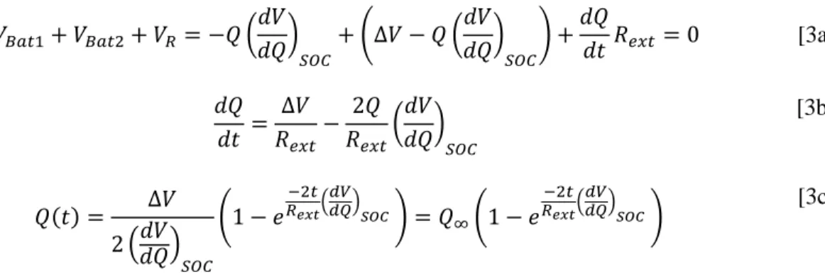
Applying Kirkoff’s second law to the circuit in Figure 3 results in Equation 3a. Both batteries in Figure 3 are at the same SOC and battery 2 is compressed, increasing its voltage by . Q is the amount of charge lost on battery 2 and gained on battery 1 (i.e., Q is the number of coulombs that pass through the circuit). Equation 3a can be rearranged into Equation 3b and solved for Q in Equation 3c using the boundary condition that at .
[3a] [3b] [3c]
The voltage across the resistor is going to be the last term in Equation 3a, and voltage as a function of time across the resistor is given in Equation 4.
[4]
8
From Equation 3c and Equation 4, as ,
and . This means
that initially, but over time, the capacitors charge up to a voltage of and the voltage over the resistor decays to zero, as expected when energy is dissipated through the system. Note that the above derivation is for a compressed battery (that is ), but that when the battery is uncompressed, the same process occurs with a negative voltage and negative current, dissipating the same amount of energy over the resistor but with current flow reversed. The total amount of energy dissipated over the resister is given by Equation 5, with a factor of two accounting for both the compression and release steps.
[5]
Because lithium ion batteries expand and contract, and strain is a strong function of state of charge, we can compare the energy dissipated over the resistor with the energy input of the compressive force as the compressed battery contracts slightly when the charge moves around the circuit [15]. The work input is given by Equation 6a, and the conservation of energy equation is given by Equation 6b. The applied force is given by , the amount of expansion by (using the standard definition of engineering strain), and the capacity of the battery by Q. We denote the energy losses as . Equation 6a represents the theoretical compressive work done by the Instron on the battery, and Equation 6b represents conservation of energy— namely that all compressive work is either lost somewhere in the circuit or is dissipated by the resistor as electrical work. Note that energy is only input during the compression, whereas energy is dissipated through the resistor during both the compression and the release.
[6a]
9 [6b] [6c] [6d] [6e] [6f]
We assume that the efficiency of this system is constant, i.e., for some
constant . With this assumption, we can solve for the initial voltage (Equation 6c) and the energy loss term (Equation 6d). The limit of is the same as , which results in
[13]. From the conservation of energy, we have rigorously
derived an expression for in Equation 6c that matches exactly the expression postulated in Equation 1 in the limit of no energy losses. In this derivation, we assume that the measured time constant is exactly
. In practice, we find that this time constant is off by a small
factor (close to unity) β such that
, where b is the measured time constant.
Combining Equations 6e and 6f, we determine that the maximum theoretical efficiency for a battery with known parameters alpha and beta is given by,
10
[7]
IV.
Initial voltage peak and state of charge
In general, there are many parameters that affect the energy harvesting system shown schematically in Figure 1. In this system, when one battery is compressed, the equilibrium potential changes and lithium ions (and electrons) move to equilibrate the potentials of the two batteries. However, both the equilibrium potential and the mechanics of the system are strong functions of state of charge. State of charge is therefore an extremely important parameter to investigate when considering energy harvesting. Other parameters of interest include: the stress applied (more stress correlates with more voltage) and the load resistance (voltage and power are functions of resistance). To investigate the parameters of the amount of energy harvested, we cycled the system with a period of one hour (enough to fit an exponential) with a stress of 10 MPa (higher stresses had adverse effects on our particular batteries over time). All averages here represent at least five cycles. The voltage as a function of time was fit to an exponential
equation of the form given in Equation 8.
[8]
Perhaps the most important parameter to investigate as a function of state of charge is the initial change in voltage the system experiences when compressed, represented in Equation 8 as
. As described in Equations 1 and 6c, the factor that determines the voltage increase at a given stress state is equal to the first derivative of strain with respect to state of charge (derived in detail in previous work) [2, 13]. Fundamentally, this derivative has been previously related to electrode phase transitions, specifically the lattice heights and equilibrium potentials of the
11
phases [15]. Other intercalation materials that exhibit phase translations can be easily evaluated for use as energy harvester with quick mechanical measurements.
Fig. 4 Comparison of the first derivative of strain (coupling factor) with parameters involved in
energy harvesting, specifically peak voltage height. The shaded region represents error on the derivative curve. Y-error on the data points is due to standard deviation of multiple cycles and x-error is estimated from observed battery differences. The ranges and scales on the second axes are chosen to best align the data according to a proportional fit
The same type of experiment from Figure 2 (with slight differences described
previously) is run at different states of charges, and the average peak heights for multiple cycles ( ) are compared to the derivative of expansion in Figure 4. This comparison is done by comparing to , quantities that should be proportional according to
Equation 6c. The y-error for the data points is the result of variations between cycles of the same battery. The x-error for the data points is chosen based on observed variations in maximum capacity of the batteries (and therefore state of charge calculations). The shaded error for the derivative is taken from manufacturer boundaries for the variations in height of the batteries and therefore their expansion and strain. The axes ranges are picked to best compare the quantities assuming a direct correlation between the data, discussed below. The measured heights and the derivative of expansion agree well have the same general trends. Using a direct fit (
), we can solve for the parameter α, as defined in Equation 6c. This fit calculation
gives . The energy losses in this process are likely due to friction, heat, and other resistive losses in the system such as increased resistance when the battery is compressed
12
[18]. Along with β, this value can help determine the maximum theoretical efficiency of this system according to Equation 7.
In our model, we assume that α is a constant, but it could be a very weak function of state of charge. For example, accounting for the factor of α in Figure 4, the measured voltage at lower states of charge is relatively larger than the derivative line but the measured voltage at higher states of charge is relatively smaller than the derivative line. This implies that α decreases slightly with increasing state of charge, indicating that the system has more energy losses at higher states of charge. Such a trend could be attributed to increased resistance of the battery at higher states of charge [18].
V.
Time Constant and State of Charge
In addition to the initial peak voltage strongly affecting the energy harvested, the time constant, , will also affect the energy harvested (smaller values mean that the voltage decays more slowly and more energy is harvested). Building on Equation 4, we will compare the experimental time constant, , with the theoretical decay factor,
. In particular, we will compare
with , where the resistance is nominally 10 Ω. Figure 5 depicts this
comparison.
Fig. 5 Comparison of measured adjusted decay constant and dV/dQ. The axes scales have been
adjusted for best viewing. Y-error represents a standard deviation, x-error represents expected variation in maximum capacity, and the gray shading represents expected variation in the derivative from variation in maximum capacity
13
The trends in the measured decay constant matches the trend in dV/dQ very well. However, the measured decay constant is 1.4 ± 0.1 times larger than expected, calculated via a direct fit (
where ). While β is essentially unity, this factor
essentially indicates that the real system decays to zero faster than the model predicts and is therefore less efficient than the model (i.e., there are unaccounted losses). This small factor could be due to the capacitive nature of the batteries not being exactly equal to dV/dQ or some other capacitive term that is not in the model. Overall, however, the comparison between dV/dQ and the measured time constant supports the model extremely well.
VI.
Energy Efficiency
The true measure of success of an energy harvester is the amount of energy harvested. Lithium ion batteries do not generate significant amounts of energy (order nW of average power
generation). However, this small amount of energy (order 1 mJ per hour) is useful for purposes such as wireless sensors that require very small amounts of energy but are not easily accessible. Additionally, lithium ion batteries are not optimized intercalation materials and other materials and configurations could potentially produce orders of magnitude more energy. According to Equation 7, . This theoretical efficiency is a constant for our system because α and β are constants.
While this calculation represents the amount of energy harvested compared to what we would expect to harvest according to our model, in practice the total efficiency of the system also has viscoelastic terms from the compression and release of the battery. From Figure 2, we
14
calculated that . This is significantly less than the . This difference is due to battery materials such as the polymer separator.
Essentially, regardless of energy dissipation, compressing and releasing the battery will always result in a significant energy loss from the viscoelasticity of the battery components. ηtheory is the
maximum theoretical efficiency of our harvesting system that assumes no viscoelastic losses and assumes that the input work comes solely from movement of the applied force due to change in battery expansion when current flows. The ηtheory is a reasonable maximum theoretical efficiency
for a graphite and LCO battery system, and other similar systems likely having comparable efficiencies.
VII. Conclusion
Lithium ion batteries are extremely important for a clean energy future and remain one of the best commercial energy storage devices. In this work, we investigated lithium ion battery materials as mechanical energy harvesters, and demonstrated that they can successfully be used to convert from mechanical to electrochemical energy in addition to storing energy. We
characterized this process using basic circuit elements and provided a model and framework to predict the relevant energy harvesting parameters such as peak voltage and efficiency from basic mechanical and electrochemical data. While our commercial lithium ion batteries are not ideal energy harvesters, they serve well as a prototype for our model and demonstrate how our model can take raw expansion and voltage data from intercalation materials and predict energy
production. From our model, we determined that the maximum theoretical efficiency for energy harvesting using these battery materials is 2.9 ± 0.5%. Other similar systems will likely have a comparable maximum theoretical efficiency. In the future, we can use this model to help predict
15
the effectiveness of other intercalation materials for mechanical energy harvesting. We can also aim to reduce viscoelastic losses, such as those from the polymer separator, and improve the real efficiency of the system.
VIII. References
1. Ramadesigan V, Northrop PWC, De S, et al (2012) Modeling and Simulation of Lithium-Ion Batteries from a Systems Engineering Perspective. J Electrochem Soc 159:R31. doi: 10.1149/2.018203jes
2. Cannarella J, Leng CZ, Arnold CB (2014) On the coupling between stress and voltage in lithium-ion pouch cells. 9115:91150K. doi: 10.1117/12.2055152
3. Muralidharan N, Carter R, Oakes L, et al (2016) Strain Engineering to Modify the
Electrochemistry of Energy Storage Electrodes. Sci Rep 6:27542. doi: 10.1038/srep27542 4. Jacques E, Lindbergh G, Zenkert D, et al (2015) Piezo-Electrochemical Energy
Harvesting with Lithium-Intercalating Carbon Fibers. ACS Appl Mater Interfaces 7:13898–13904. doi: 10.1021/acsami.5b02585
5. Sheldon BW, Soni SK, Xiao X, Qi Y (2012) Stress Contributions to Solution Thermodynamics in Li-Si Alloys. Electrochem Solid-State Lett 15:A9. doi: 10.1149/2.016201esl
6. Sethuraman V a., Srinivasan V, Bower a. F, Guduru PR (2010) In Situ Measurements of Stress-Potential Coupling in Lithiated Silicon. J Electrochem Soc 157:A1253–A1261. doi: 10.1149/1.3489378
7. Sethuraman V a., Chon MJ, Shimshak M, et al (2010) In situ measurements of stress evolution in silicon thin films during electrochemical lithiation and delithiation. J Power
16
Sources 195:5062–5066. doi: 10.1016/j.jpowsour.2010.02.013
8. Massey C, McKnight G, Barvosa-Carter W, Liu P (2005) Reversible work by electrochemical intercalation of graphitic materials. 5759:322–330. doi: 10.1117/12.601491
9. Xu S, Hansen BJ, Wang ZL (2010) Piezoelectric-nanowire-enabled power source for driving wireless microelectronics. Nat Commun 1:93. doi: 10.1038/ncomms1098 10. Wang ZL, Song J (2006) Piezoelectric nanogenerators based on zinc oxide nanowire
arrays. Science 312:242–246. doi: 10.1126/science.1124005
11. Qin Y, Wang X, Wang ZL (2008) Microfibre-nanowire hybrid structure for energy scavenging. Nature 451:809–813. doi: 10.1038/nature06601
12. Koka A, Sodano H a. (2014) A Low-Frequency Energy Harvester from Ultralong, Vertically Aligned BaTiO 3 Nanowire Arrays. Adv Energy Mater n/a-n/a. doi: 10.1002/aenm.201301660
13. Cannarella J, Arnold CB (2015) Toward Low-Frequency Mechanical Energy Harvesting Using Energy-Dense Piezoelectrochemical Materials. Adv Mater n/a-n/a. doi:
10.1002/adma.201502974
14. Kim S, Choi SJ, Zhao K, et al (2016) Electrochemically driven mechanical energy harvesting. Nat Commun 7:10146. doi: 10.1038/ncomms10146
15. Schiffer ZJ, Cannarella J, Arnold CB (2016) Strain Derivatives for Practical Charge Rate Characterization of Lithium Ion Electrodes. J Electrochem Soc 163:A427–A433. doi: 10.1149/2.0091603jes
16. Pharr M, Suo Z, Vlassak JJ (2013) Measurements of the fracture energy of lithiated silicon electrodes of Li-Ion batteries. Nano Lett 13:5570–5577. doi: 10.1021/nl403197m
17
17. Smith a. J, Dahn JR (2012) Delta Differential Capacity Analysis. J Electrochem Soc 159:A290. doi: 10.1149/2.076203jes
18. Cannarella J, Arnold CB (2013) Ion transport restriction in mechanically strained separator membranes. J Power Sources 226:149–155. doi: