Publisher’s version / Version de l'éditeur:
Journal of Thermal Envelope & Building Science, 23, July 1, pp. 78-94, 1999-07-01
READ THESE TERMS AND CONDITIONS CAREFULLY BEFORE USING THIS WEBSITE. https://nrc-publications.canada.ca/eng/copyright
Vous avez des questions? Nous pouvons vous aider. Pour communiquer directement avec un auteur, consultez la
première page de la revue dans laquelle son article a été publié afin de trouver ses coordonnées. Si vous n’arrivez pas à les repérer, communiquez avec nous à PublicationsArchive-ArchivesPublications@nrc-cnrc.gc.ca.
Questions? Contact the NRC Publications Archive team at
PublicationsArchive-ArchivesPublications@nrc-cnrc.gc.ca. If you wish to email the authors directly, please see the first page of the publication for their contact information.
NRC Publications Archive
Archives des publications du CNRC
This publication could be one of several versions: author’s original, accepted manuscript or the publisher’s version. / La version de cette publication peut être l’une des suivantes : la version prépublication de l’auteur, la version acceptée du manuscrit ou la version de l’éditeur.
Access and use of this website and the material on it are subject to the Terms and Conditions set forth at
Moisture management of EIFS walls -- Part 1: The basis for evaluation
Bomberg, M. T.; Kumaran, M. K.; Day, K.
https://publications-cnrc.canada.ca/fra/droits
L’accès à ce site Web et l’utilisation de son contenu sont assujettis aux conditions présentées dans le site
LISEZ CES CONDITIONS ATTENTIVEMENT AVANT D’UTILISER CE SITE WEB.
NRC Publications Record / Notice d'Archives des publications de CNRC: https://nrc-publications.canada.ca/eng/view/object/?id=7a65c276-619f-40be-85e2-c80ef1af8db0 https://publications-cnrc.canada.ca/fra/voir/objet/?id=7a65c276-619f-40be-85e2-c80ef1af8db0
http://www.nrc-cnrc.gc.ca/irc
M oist ure m a na ge m e nt of EI FS w a lls -- Pa rt 1 : T he ba sis for
e va lua t ion
N R C C - 4 3 3 9 4
B o m b e r g , M . T . ; K u m a r a n , M . K . ; D a y , K .
J u l y 1 9 9 9
A version of this document is published in / Une version de ce document se trouve dans: Journal of Thermal Envelope & Building Science, 23, (1), July, pp. 78-94, July 01, 1999
The material in this document is covered by the provisions of the Copyright Act, by Canadian laws, policies, regulations and international agreements. Such provisions serve to identify the information source and, in specific instances, to prohibit reproduction of materials without written permission. For more information visit http://laws.justice.gc.ca/en/showtdm/cs/C-42
Les renseignements dans ce document sont protégés par la Loi sur le droit d'auteur, par les lois, les politiques et les règlements du Canada et des accords internationaux. Ces dispositions permettent d'identifier la source de l'information et, dans certains cas, d'interdire la copie de documents sans permission écrite. Pour obtenir de plus amples renseignements : http://lois.justice.gc.ca/fr/showtdm/cs/C-42
IAuthor to whom correspondence should be addressed.
Moisture Management ofEIFS
Walls-Part 1: The Basis for Evaluation
MARK BOMBERG1AND KUMAR KUMARAN
Institute for Research in Construction National Research Council Montreal Road, Building M20 Ottawa, ON, Canada KIA OR6
1097-1963/99/010078-17 $10.00/0
©1999 Technomic Publishing Co., Inc.
J. THERMAL ENY. & BI.DG. SCI. Volume 23-JH/y 1999
78
KEVIN DAY
Morrison Herslifield Ltd.
Consulting Engineers 4 Lansing Square
North York, ON, Canada H2] 11'4
ABSTRACT: The Canadian approach to design accepts the presence of some con-struction deficiencies and calls for a multiple-line of defense. Until now, such a design has been based on the qualitative。ウウ・ウウュ・ョエセ rooted in experience, i.e., tradition, and involved little integration with the newly emerging analytical tools, e.g., advanced hygrothermal models. The relation between the design and climatic conditions acting on a building is not well established. Research should be undertakentoclarifY the rela-tionship between climate and the moisture performance of a given wall assembly, i.e., to enhance the predictability of moisture performance for different wall assemblies when constructed with some deficiencies and exposedtoa given climate.
To improve the correlation between climatic conditions and design practice, mois-ture management of a building envelope must involve the flow-through principles. The flow-through approach is, however, much more difficult than the currently used approach with barriers. The flow-through approach requires performing computer calculations of moisture balance of all layers of the wall with regard to heat, air and moisture transport over an entire year. This is the critical element of the integrated moisture management strategy.
)0-Ign LOd :ed mg エ。セ .c., les IS-lCS. cd )9 " セ• • J "
Moistlire Management of EIFS walls-Part 1: The Basisfor Evaluation 79
design process. This paper provides the background and sets the stage for a rational evaluation of moisture perfomunce of cladding systems. The next paperwill define the classification of EIFS with respect to moisture management. The th.ird paperwill discuss the selection of EIFS and the fourth paper will review the critical aspects of quality assurance.
INTRODUCTION
O
NE HASONLYto look at the list ofpapers published during the past fewyears to appreciate the wide consideration given to the topic of
long-term performance of Exterior Insulation and Finish Systems (EIFS). Re-search resulted in various new designs and new technical solutions. To en-hance a systems approach for evaluating long-term performance of EIFS, the authors decided to review the emerging systems with respect to the po-tential moisture management strategies inherent in these new designs.
This task is accomplished in four parts, published as separate papers. The first paper provides background for moisture management concepts; it nei-ther evaluates the performance of the systems nor provides comparative ranking; it only aims at providing the frame of reference in which such sys-tems are evaluated. The second paper lists the actual moisture management strategies, and the last two review the approach to EIFS selection and quality assurance. Thus, for each EIFS type the moisture management strategies and details critical for EIFS construction are discussed and documented with a view to ensuring field performance.
DESIGN FOR ENVIRONMENTAL CONTROL
In designing for environmental control (heat, air, and moisture transfer), professionals integrate two very different conceptual approaches. One in-volves specific testing and analysis; the other encompasses broad qualitative assessments based on experience,judgment and knowledge of what makes a building envelope function.
On the analytical side, there is a complex array of tools: hygrothermal models, banks of material properties, analysis of environmental factors relat-ing to the buildrelat-ing envelope. On the qualitative side, a particular buildrelat-ing envelope is seen from a functional point of view.
For example, a vapor barrier is classified at one perm, a unit that represents sufficient retardation of moisture flow for wood-frame housing. However, when calculations were made using an advanced model of heat, air and moisture transport for various climatic conditions in Canada, barriers rang-ing from 0.2 to 7 perms were found suitable for various combinations of materials and climates (Karagiozis and Kumaran, 1993).
Reliability of the Design
Through experience, the Canadian precept for building envelope design incorporates precautionary measures to avoid harmful accumulation of moisture in critical parts of the envelope. Theoretically, building profession-als-be they designers, specifiers or builders-can design and construct a perfect structure. Yet, in practice, sooner or later the imperfections will re-veal themselves. Water enters, for instance, because the roof drainage does not lead water away from the building but directs it right to the basement, or caulking in a face-sealed design is not maintained during the service life and therefore leads to water penetration. We know that eventually some mois-ture finds its way into the building envelope. So the walls are constructed to permit draining and drying of any incidental moisture accumulation. But how long would it take to dry out, and what effect would the moisture have on various materials? As there are not many quantitative answers, designers must look to logic and experience.
A significant effort was made to measure vapor transmission through many construction materials during the last four decades. Yet, this effort did not enhance the reliability of moisture management in construction. The benchmark ofone perm, introduced about50 years ago, is still only a bench-mark (even though many building codes present this benchbench-mark as an im-portant criterion).
To advance moisture management in construction, we cannot restrict our discussion to one concept at a time. Over the last two decade, construction industry in North Amt::rica went through three "campaigns" for (1) vapor retarder (called vapor barrier in Canada), (2) air barriers, and (3) pressure equalized rain screen. Each campaign was thought to establish a panaceum for moisture management. While all the three elements (vapor barrier, air barrier, and rain penetration control) are important, none of them can be discussed without the others. Only the holistic and comprehensive ap-proach to moisture management, such as the one expressed by Hutcheon in
1963-ro control heat, air and moisture flows-withstood the test of time. Experience tells us that most of the traditional wall assemblies will per-form wdl in a dry, mild or moderately cold climate. The more extreme the climate, the smaller is the selection of walls with proven long-term perfor-mance. It is expected that on-going research will enhance the understanding of the relationship bdween climate and moisture performance of a given wall assembly. The outcome of research is expected to enhance predictabil-ity ofmoisture performance for different, not necessarily perfect wall assem-blies, in a given climate. How imperfect these walls are may depend on many factors.
c
MARK BOMBERG, KUMAR KUMARAN AND KEVIN DAY
.
',,"Moisture Management of EIFS Walls-Part 1: The Ba.ds.ftn Evaluation 81
The need for additional precaution forces designers and builders to pre-pare for the eventualities they cannot predict, such as material changes caused by aging or weathering, flaws in workmanship issues or even design flaws that may escape their notice. Typical, unnoticed leakage paths occur when air travels through more than one building component, e.g., air pass-ing through a part of masonry where wall pargpass-ing is not finished, or behind radiator cabinets, or through holes used to pass wires to the suspended ceil-ing or corrugated roof decks. The list of leakage paths also includes large masonry partition walls that stretch above the roof, openings cut for electri-cal heating, ventilation and plumbing services, cladding materials that are not drawn tight to metal studs and furred partition walls connecting with a suspended ceiling. Air leakage is likely to occur if the drywall is carried just above the ceiling plenum and does not meet the floor to form continuous and airtight connection.
Buildability
Similar to the precautionary measures, buildability relates more to judg-ment and knowledge of the professional than to mathematical analysis. Buildability reflects whether a specific design can be constructed on site, by various trades, without compromising the functional requirements of the wall. Contrary toa frequent misconception, buildability is more related to a good design than to superior workmanship. As experience indicates, only a good design can combine responses to all the environmental factors and produce an easily assembled construction sequence. For the most part, it is the designer who attends to the aspects of buildability such as material stallation under different weather conditions, level of skill required for in-stallation, and construction tolerances. Often buildability problems are caused by the interaction and sequencing of different trades. As a rule, none of the following: window manufacturer, window installer, interior fin-ish/drywall installer would consider the window/wall interf:1Ce as their re-sponsibility.
Other Key Design Considerations
The design of building envelopes for environmental control requires a number ofiterations. Each material must be examined with regard to its com-patibility and interaction with the adjacent materials and components. Each modification of the performance requirements or change in the material se-lection must be followed by a review of architectural details. These issues highlight the importance of a review (in a sense, troubleshooting) ofdrawings of the assembled system and of the design details. To maintain a high standard
A HISTORIC VIEW OF MOISTURE MANAGEMENT OF EIFS CLADDING
ofquality and clarity, some specifiers prefer to have one section of the specifi-cation addressing the joints and Junctions ofvarious sub-assemblies within the overall building envelope system. In this respect, it is difficult to draw the line between concepts of buildability and the precautionary measures. Both ad-dress aspects of the system during both its constmction and its service life. Yet, so often, the key to good and long-term performance of the system de-pends on the performance of the architectural details.
Walls with EIFS contain a substrate (the supporting system) and the clad-ding system. The latter is composed of an insulation board (attached with adhesive and/or mechanical fasteners), a synthetic coating system consisting of one or more layers of a base coat with an alkali-resistant reinforcing glass fibre mesh, and a finish coat. The synthetic coating system is commonly called the lamina. Each of these components has a clearly defined function such as mechanical support (strength and rigidity), reduction of heat flow, bonding (adhesion), resistance to crack initiation, resistance to water ingress, and appearance.
EIFS-type claddings have been classified as Polymer Based (PB) and Poly-mer Modified (PM) systems. ForPoly-merly these systems were classified as soft coat, thin and flexible for PB, and hard coat, thick and rigid for PM. The words, soft, thin, and flexible are attributed to the high polymer content in the base coat that results in a flexible thin coating, while the words hard, thick, and rigid are attributed to the relatively low polymer content that re-sult in a less flexible coating. The cement content does not exclusively sepa-rate these two systems. Most PB base coats contain cement, yet some do not. The components of the two systems are largely identical, except for the thickness of the base coat and the method of attachment. The performance characteristics are inherently different. The critical difference of the base coat thickness and hardness of the PM systems traditionally required that control joints be provided.
Traditionally, wall systems with EIFS cladding were considered face-sealed (barrier) walls, which means that the exterior face is expected to pro-vide most of the functional requirements of the wall and, in particular, to act as the primary (and often the only barrier) to rain ingress. The exterior face, however, includes also fenestration, penetrations, and connections Uoints and junctures) between all the components of the building envelope. All these penetrations must be equally impermeable to water, if the face-seal ap-proach is to work.
MARK BOMBERG, KUMAR KUMA RANAND KEVIN DAY
\.>
Moisture Managementセイ EIFS Walls-Part 1:The BasIs ,{£)r Evaluation 83
The rain barrier created by the EIFS lamina must remain impermeable to water during its expected service life. The effects of weathering, aging of materials, cracks in the lamina, and the possible deterioration of the wall substrate, as well as service penetrations through the wall, must be included in the evaluation. Therefore, not only the initial performance of the wall system but also its long-term performance under service conditions must be
・カ。ャオ。エ・、セ
Although examples of satisfactory long-term performance of EIFS abound, there have been also failures of waIls with EIFS, notably failures of the substrate once rain water has penetrated through thejoints andjunctures and become trapped within the wall system. Sealant joint failures have been reported frequently during this decade, e.g., Williams and Lamp-Williams, 1990; Meyers and Ruggiero, 1991; STP, 1995. Recent moisture problems in Wilmington, NC, and Vancouver, BC, which led to prohibition of field-applied, face-sealed systems in Vancouver (1995) and North Carolina (1995) were well publicized. Note that these types of regions have particularly ad-verse climatic conditions.
The central issue ofEIFS system evaluation is the management ofmoisture to ensure system integrity during many years of adverse climatic conditions. During this evaluation, one often faces the dilenuna whether EIFS is a com-ponent evaluated in the context of an entire waIl, or a separately evaluated dadding system. Cladding is a component of the waIl and the functional re-quirements of cladding need not be as extensive as those for the entire wall. Exterior cladding is defined as "those components ofa building which are ex-posed to the outdoor environment and are intended to provide protection against wind, water and vapor,,2 or "the non-load bearing clothing of the walls and roof ofa building, the skin used to keep the weather out.,,3
The commentary on Part 5 (dealing with large buildings) ofthe 1990 edi-tion of the Naedi-tional Building Code (NBC) ofCanacla states:
"When the sealants of a face-sealed cladding fail, the walls lose their water tightness and air tightness; this translates into severe disability ofthe envelope in performing its intended functions. As a consequence, face-sealed walls require frequent and costly maintenance during the life ofbuilding. The approach has little to recommend it and is considered impractical for buildings in Canada."
Brown4 reviewing Part 9 (dealing with housing and small buildings) of the same NBC stated:
2NationaJ Building Code of Canada,1990edition.
3Scott,]. S., Dictionary of Building, Penguin Books Ltd., Harmondworth, Middlesex, UK,
1974.
The review of the scientific basis for moisture management in a building
NEED FOR THE SYSTEMATIC APPROACH TO MOISTURE MANAGEMENT
SAs Straube points out in the private communicationtothe authors, the 6 mm requirement is there to ensure that the lath gets well keyed into the stucco, as it should be placed in the mid-dle ofthe plaster; the drainage comes from the requirement for a capillary break at the build-ing paper or sheathbuild-ing membrane that is required beneath the stucco.
MARK BOMB ERG, KUMAR KUMARAN AND KEVIN DAY
84
"Part 9 of the Code also generally accepts that cladding alone cannot be ex-pected to provide protection from rain penetration. The intended perfor-mance of exterior cladding, as outlined above, to prevent the passage of water and provide drainage ifthere is a likelihood ofpenetration is essentially covered within Part9by listing acceptable sidings (section9.27)and requirements for a sheathing membrane (subsection 9.23.17) beneath siding. The requirement for self-furring devices to hold stucco lath6mmfrom the backing(9.28.4.4) is essentially a requirement that stucco be constructed with a drainage layer"; in other words, the probability that the cladding will leak is presumed to be not
" zero.
Thus, in Canada, most experienced designers do not rely on sealants as the long-term nieasure of controlling rain penetration. A single-stage seal-ant joint, as in one bead ofsealseal-ant with a dosed cell backer rod, was once the norm. However, other solutions, such as drainable two- or single-stage joints with secondary protection (expanding foams and gaskets, etc.) are becoming increasingly more common.
In summary, while the Canadian approach to design appeared to be on the safe side, accepting the presence of some design or construction defi-ciencies and calling for a multiple-line of defense, it has been entirely based on the qualitative assessments rooted in experience, i.e., tradition. It did not require any integration with the analytical side of the design process.
With such failures as the stucco walls in Vancouver, or the EIFS walls in North Carolina, the North-American approach to moisture management of a building envelope did not provide for adequate relations between de-sign practice and climatic conditions. This situation must be changed. To achieve this objective, the incorporation of the analytical side of moisture management-with its vast array of tools, models and quantifying methods for structural and environmental factors rdating to the building envelope-may be needed. Furthermore, we need to make the design process more transparent and focussed on suitable means for quality assurance. Such changes are necessary to accommodate a growing supply of new construc-tion materials and components.
Moj.-ture Management of EIFS Walls-Part 1: The Basis/or ElJaluation 85 envelope must start with rain penetration control. Rain £'l1ling on the wall surface can flow down (be shed), stored (absorbed by material or attached by surface tension), or transmitted into the wall. Some of the water flowing onto the wall sur£lce may be removed from the surface by features such as drips and ledges.
Rain Control and Design Strategy6 Straube and Burnett (1997) discuss three design strategies: • face-sealed (barrier wall) or perfect barrier system
• moisture storage system • screened and drained systems
FACE-SEALED (BARRIER WALL)IPERFECT BARRIER SYSTEM A multi-layer enclosure assembly may contain a single layer where the amount of rainwater transmitted inward must be zero. The water-impermeable layer is often located on the exterior face of an assembly. Such a rain control strategy has been termed "face-sealed" or "barrier walls."
In principle, drainage and storage within the assembly do not play any roleinproviding rain control in functional face-sealed (perfect barrier7)
sys-tems.
MOISTURE STORAGE SYSTEM
When there is enough moisture storage to absorb all rainwater that is not shed from the outer surface, the wall assembly can also prevent moisture penetration through the wall.
Although envelopes employing this strategy might be termed "moisture storage" systems, "mass walls" are often used to denote a large mass required for providing sufficient storage. The water transmission of the various layers and interfaces can playa critical role in the performance of mass systems. Straube and Burnett (1999) give an example of a 300-mm thick, solid-brick masonry wall. By applying 15-mm thick, PM cement rendering, the storage capacity is only marginally increased, but the water transmission of this outer layer, even when cracked, is so low that the rain penetration control of the system is vastly improved. In effect, performance of mass walls depends
6This section is based on the work ofStraube and Burnett(1997, 1999).
71t may seem that "perfect barrier" is a redundant term, but the building industry almost always uses the term "barrier" in a relative, not absolute, sense, e.g., vapour barrier and moisture bar-rier. Therefore, it is deemed necessary to qualify the barrier as being perfect.
SCREENED AND DRAINED SYSTEM
Rain Control Performance of Actual Walls Straube and Burnett (1999) state:
MARK BOMBERG, KUMAR KUtMRAN AND KEVIN DAY
86
on the moisture storage and water transmission characteristics. Finally, the ability of materials to dry is critical for the performance of such a wall.
The performance of mass walls depends heavily on weather conditions. If a series of rain events occurs and drying conditions are poor, the storage ca-pacity may be exceeded, resulting in the failure to limit water intrusion. While theoretically speaking, the mass walls do not require any drainage ca-pability, these are routinely provided in masonry construction.
"This is not necessarily because the lamina (the plane assumed by designers to be perfectly watertight) allows no transmission, but rather that the substrate has "Another approach to controlling rain is to accept that some water will pene-trate the outer surface (hence the cladding "screens" rain) and to provide drain-age to remove it. The draindrain-age need not be provided at one layer only. In fact, if all the drainage was provided by one layer only, the wall would be acting as a perfect barrier system. Screen and drained walls control rain penetration by re-ducing the amount of water transmitted at each of several layers.
The drained enclosure systems control rain penetration by reducing the suc-cessive fractions of water that are transmitted inward. Almost without excep-tion, functional rain screen walls provide several additional drainage layers, for example, the front and back of the sheathing paper. Modern windows, car doors, and two-stage j oints are exceptions, in that they typically have precisely two layers (hence two stage control mechanism). Although these types ofjoints provide an "almost" perfect inner layer, the intent ofthe outer layer is to signifi-cantly reduce the potential for any water on the second layer."
In principle, the screened-drained wall system does not require any stor-age capability.
Finally, there are two special cases of screened and drained system, where the transmission fraction of the screen is reduced by modifying air pressure. These systems are called "pressure-equalized" or "pressure-moderated" rain screen.
While the classification of the rain control strategy in itself does not bene-fit the architect or designer, it brings, however, into focus some fundamental issues involved in the process of design. First, it explains why many face-sealed wall systems function despite the documented existence of cracking and penetrations through EIFS lamina. As Straube and Burnett (1999) state:
',:-'
Moisture Management of EIFS J#llls-Pl1rt 1.'The Basisfor ElJl1hlation 87
sufficient storage to store the small fraction that penetrates. In other cases, this storage capacity may act in conjunction with drainage that is inadvertently provided by interface layers and large pored or fibrous insulation materials. In most reported cases, EIFS fail because ofvery high exposure and poor detailing of the joints and penetrations, e.g., windows.
It is likely that many rain control failures ofEIFS are the result ofextreme expo-• sure conditions and insufficient safe storage capacity behind the (often) some-what less-than-perfect lamina. The inability of some types ofEIFS systems to dry once rain penetrates often results in other serious performance and dura-bility problems (for example, the well-publicized cases in Wilmington, North Carolina) ."
Typically, we recognize failure in two cases:
1. when water penetrates through an entire assembly to the inner surface of the wall
2. when the transmission ofrainwater reaches a sensitive layer ofthe wall as-sembly and is likely to cause damage, degrade performance, or affect its durability.
While in modern construction, the first type of failure is extremely rare, the second type highlights the question: what level of moisture is accept-able? Evidently, moisture management involves not only the environmental conditions and material hygrothermal properties, but also the "moisture sensitivity" of different construction products. (The concept of moisture sensitivity has evolved with time. Originally, it involved only the moisture effects on durability. Now, it also includes other moisture effects such as mold or fungus growth, i.e., phenomena affecting indoor environment.)
With discussing screened and drained-wall systems, Straube and Burnett (1999) highlight that storage also plays an important role in those walls. For
example, only during extended rainy periods and ゥョエセjjセ⦅セイ。ゥャQエZyセョエウLキィ・ョ _ the veneer may become saturated, the drainage function becomes critical.
The storage capacity of such walls suggests that in most exposure conditions, they afe actually behaving as mass walls aided with water-retarding layers, e.g., building paper. While these walls may be functional in some weather conditions, this may not be so in a different climate. With more driving rain deposition-e.g., near the top of high-rise buildings-or less drying poten-tial-e.g., Halifax, Vancouver or other rainy, coastal climates-the storage capacity can be exceeded, resulting in the leakage of water into the wall as-semblies.
In
effect, Straube and Burnett (1999) do not accept the simplified picture ofrain penetration control where one or two layers provide all the necessary controls either through drainage Of through barrier functions. They postu-late that even when one fraction dominates the design, all fractions(drain-FIGURE 1. Schematic of environmental functions in a frame wall used in cold climates.
Ira in screen Islline of defense
I
ャG、イ。ゥョセァセl。Zエ・イRョ、ャゥョ・
of defenseI
MARKBOMBERG, KUMAR KUMARAN AND KEVIN DAY
/lairga p
88
Environmental Control Functions: Example of a Wood-Frame Wall
age, storage and transmission) play an important role in almost all wall sys-tems. Ifsome storage and drainage is possible in walls considered designed as barrier walls, these walls may not fail even if the barrier is imperfect. In the same way, many drained-screened walls may, in fact, have poor drainage and therefore can only function when sufficient storage is available.
Introducing moisture storage into rain penetration control broadens the scope of our analysis. Moisture storage is affected by such phenomena as thermally driven redistribution of moisture as well as air leakage. In effect, moisture storage brings all environmental parameters into consideration. The following section will provide a brief overview of the complexity of this fldd of concerns.
The environmental control functions of the frame wall construction are schematically shown in Figure 1. After the rain screen, the next environ-mental functionS shown in Figure 1 pertains to a cavity, the air gap. It
con-tributes to two aspects of moisture performance:
• control of rain penetration by reducing the intensity of rain carried across the air gap
8Each environmental function mayor may not be fulfilled by one specific material or compo-nent of the building envelope.
Moistlire Management of EIFS rMtlls-Part 1:The Basis}Or Eva{IIatiorl 89
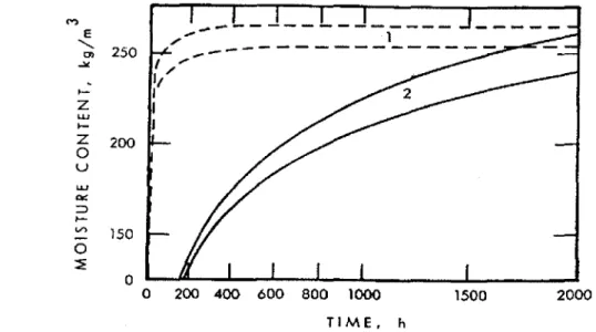
FIGURE 2. Moisture gained by initially dry, aerated concrete specimens from wet gypsum specimens, Two levels of moisture content in gypsum and two different conditions at the in-terface between specimens: (1) Samples in contact and (2) samples separated by 1-mm air gap (Bombrerg, 1974). 2000 1500
o
o 200 400 600 800 1000 TIME. h 250 150 200• removal of residual rain and summer condensation ofvapor (with wall sur-face temperature varying between day and night, the direction of thermal gradient in the outer layer of the wall changes and may cause moisture to move back and forth), unless it is removed through the air gap.
The drainage function of the air gap is often underestimated. There is a history of proven performance of the cavity space in frame walls and in ma-sonry walls (double-wythe brick veneer). Only recently, when completely filling these cavities with foams or fibrous insulation and causing moisture problc;ms in renovated walls, have we started to appreciate more the impor-tance of a free of obstructions, drainable air space. The air space mayor may not be ventilated.
Whether this air gap is ventilated or not is often much less important, since its main purpose is to serve as a capillary break. (Figure 2 illustrates the power of an air gap in this respect.)
Figure 2 shows a large difference in the rate of moisture transport caused by a break of direct contact between two materials. The same moisture content was reached either in 20 or in 2000 hours. Obviously, this ratio is not a con-stant but depends on the capillary nature of both materials, yet it is evident that moisture is moved initsliquid phase much faster than in its vapor. Even a small break in continuity breaks the capillary flow ofwater and presents a dra-matic reduction in the rate ofmoisture transport. One can also infer from Fig-ure 2 that drainage is the most powerful method of moistFig-ure removal.
M E ... 0> セ
- 0-Z UJ I -Za
u LLJ -' a=: セ I -...a
セThe next functional element shown in Figure 1 is the drainage plane which, in addition to drainage of rain that may find its way to the inner sur-face of the air gap, reduces the so-called wind-washing effect. When the plane of air tightness in the air barrier system is on the internal side of the wall, wind could enter and exit from the external side of the wall.
The next functional element (see Figure 1) is a thermal insulating sheath-ing placed on the cold side of the wall frame. Its role is particularly impor-tant in highly insulated wood- or steel-frame walls. In the latter case, metal studs act as powerful thermal bridges when insulation is inserted between the studs.
The next functional element shown in Figure 1 on the warm side of the cavity insulation is an air barrier plane (plane of air tightness). Section 5.4 of the 1995 National Building Code of Canada describes performance re-quirements for an air barrier system. The plane of air tightness must reduce the air leakage to less than 0.0211(s·m2) when tested at a 75-Pa pressure
dif-ferential.
Finally, the last functional element, the vapor retarder, has received a dis-proportionate amount of attention. One explanation is that the vapor diffu-sion is one of the few moisture transport mechanisms that are easy to calcu-late. Nevertheless, these calculations can only be used to establish the onset of condensation. Because the condensation process makes these simplified calculations invalid, they cannot be used to determine the quantity of con-densed moisture.
Often, to be on the safe side, practitioners do not allow any condensation within the building structure. This type of approach is called moisture de-sign with barriers.
Conversely, moisture design with a flow-through approach permits mois-ture accumulation on an intermediate basis. This approach requires per-forming experiments or calculations to estimate how much moisture will accumulate within the building envelope during the critical season. Then, one must assess the potential effects of this moisture on the structure dura-bility. If the durability of materials and components is not adversely affected, one must check whether the drainage and drying capability over the re-maining part of the year will exceed the condensed amount. Moisture is lowed to accumulate during the heating or cooling seasons, but it is not al-lowed to accumulate from one year to another.
Normally, the use of the flow-through approach is more difficult than that of the barrier approach. Flow-through approach requires computer calcula-tions of the moisture balance over the entire year during which the wall as-sembly is exposed to the worst set of probable climatic conditions.
Figure 3 illustrates these two different design principles with an analogy to a barrel. No liquid is delivered to Barrel A and none is flowing out (design
9Phase changes may occur daily because of solar or night radiation.
B
0%
RH
30'%
100%
Moisture Management of EIFS Walls-Part 1:The Basisfor EVllll/atiofl 91
Environmental Control Functions of the Wall-A Summary
FIGURE3. Two approaches[0moisture design: (A) design with barriers and (13) design on
the flow-through principle.
with barriers). The same quantity flows into Barrel B as it flows out and the balance does not change (flow-through on a yearly basis).
Note that the moisture flow is seldom one-dimensional, and that flow-through invariably involves both the liquid flow and the vapor diffusion. Actually, the more drainage occurs during phase changes of moisture9 en-trapped within the enclosure, the more efficient is the flow-through design. The name flow-through was selected to emphasize an important aspect of the design, called moisture tolerance of the building system. A well-designed building system is not significantly affected when some moisture enters the structure because of mistakes or unforeseen circumstances. There is no damage to materials, and the system allows for subsequent drainage and drying.
An old adage states that the "proof of the pudding is in the eating." Simi-larly, the example ofenvironmental control functions ofthe wall highlighted a few critical issues.
First, we observe the role of air gap as the capillary break. Reducing or eliminating capillary flow of water significantly reduces the rate of moisture
\
CONCLUSION
To be on the safe side, the design must accept some deficiencies and use a multiple-line of defense. So far, however, the design has been entirely based on the qualitative assessments rooted in experience, i.e., tradition, and in-volves little integration with the newly emerging analytical tools, e.g., com-puter models.
This situation must be changed to improve the relationship between the design and climatic conditions. This change may require incorporation of the analytical side ofmoisture management, with its vast array of tools, mod-els and quantifYing methods that relate environmental factors to the build-transmission through the wall. The air gap also L1Cilitates drainage. For the purpose of capillary break and drainage, the nile of thumb requires the cav-iry depth is about 6 mm.
Where removal of moisture from the air cavity is concerned, a distinction has to be drawn between four different rypes of air cavities:
1. closed (non-vented)
2. vented (through openings or porous materials) 3. ventilated
4. pressure-moderated (pressure-equalized)
The difference between 2 and 3 is vague. The ventilated caviry is assumed to have a "significant" amount of airflow.
Secondly, we observe multi-dimensional character and strong interactions between heat, air and moisture flows. When we talk about control of water vapor, we think about moisture coming from indoors, in cold climates; or from the outdoors, in hot and humid climates. We rarely think about mois-ture entering the wall from rain. Yet, sometimes the presence of deficiencies provides a coupling between rain ingress and vapor movement. In one case study, rain penetration into the leaky masonry walls coincided with negative indoor pressure created by the HVAC (Lstiburek, 1995). The water evapo-rated and vapor was carried inward with moving air.
Finally we observe that the design with barriers belongs to the tradition of prescriptive design. To correlate climatic conditions and design practice, moisture management of building envelope must be quantified. Similarly, to Straube and Burnett (1999), who argued that screened and drained walls control rain penetration by reducing the amount of water transmitted at each of several layers, we must consider performance of all layers of the wall with regard to heat, air and moisture. This is the critical element of the moisture management strategy.
MARK BOMBERG, KUt'MR KUMARAN AND KEVIN DAY
/ j
".
Moisture Management of EIFS Walls-Part 1:The Basis{i.>r Evaluation 93
mg envelope. Furthermore, the design process needs to become more transparent and focussed on means suitable for quality assurance. Such changes are necessary to accommodate a growing supply of new constmc-tion materials and components.
To facilitate the correlation between climatic conditions and design prac-tice moisture management of building envelope must be quantified. To this end, one must consider the flow-through that involves performance of all layers of the wall with regard to heat, air and moisture. The flow-through approach is, however, much more difficult than that of the barrier approach. Flow-through approach requires performing computer calculations of moisture balance over an entire year on the wall assembly that is exposed to the worst though probable climatic conditions. This is a critical element of the moisture management strategy.
This paper provides a background for moisture management strategies for EIFS. The next paper will provide a moisture management classification for EIFS, which later form the basis for incorporation of analytical tools into EIFS wall design process.
ACKNOWLEDGEMENTS
The authors are grateful to Peter E. Nelson, Simpson Gumpertz and Heger Inc., Arlington, MA;]ohn Straube, University of Waterloo, ON and Fadi Nabhan, Canadian Construction Material Centre, National Research Council, Ottawa, ON for their contribution to this paper.
REFERENCES
Bomberg M., 1974. "Moisture Flow through Porous BuildingMaterials."Ph.D.the-sis at the Lund Institute of Technology, Report 52, LTH, Lund, p. 188.
Karagiozis A. N. and M.K. Kumaran, 1993. "Computer Model Calculation on the
Performance of Vapour Barriers in Canadian Residential Buildings,"
ASHRAE, Transactions Vol. 99(2) pp. 991-1003.
Lstiburek,j, W, 1995. "Two Case Studies with Failures in the Environmental Control
of buildings," Journal of Thermal Insulation and Building Envelopes, Vol. 19,
pp.149-160.
Meyers j,c. and S.]. Ruggiero, 1991. "Building Facade Watertightness,"ASTM STP
1107,pp. 11-39.
STP, 1995. "Development, Use, and Performance of Exterior Insulation and Finish
Systems,"ASTM STP1187, M. Williams and R. Lampo, Eds., American
Soci-ety ofTesting and Materials, Philadelphia, several papers deal with moisture per-formance ofEIFS.
Straube,J.f and E.fP. Burnett, 1997. "Rain Control and Screened Wall Systems,"
Proc.o{the 7th C"I1{erence011 Bllilding Science and 'I,chll%gy,Toronto, Mar. 20-21,
pp.17-37.
Straube J. and E. fP. Burnett, 1999, "A Review of Rain Control and Design Strat-egies,"].,,[Thermaleョセ alld Blli/d. Science, Vol. 22,]uly (in press).
Williams, M.F and B. Lamp- Williams, 1990. "Sealant Usage for ElI'S,"ASTM STP
1069,pp.175-194.